


Contents
Features ................................................................................................................................................. 1
Functional components ....................................................................................................................... 2
Front Panel ....................................................................................................................................... 2
Rear Panel ........................................................................................................................................ 3
Operation ............................................................................................................................................... 4
Equalizer Controls ............................................................................................................................ 4
Manual Priority Terminals ................................................................................................................. 4
Connectios ........................................................................................................................................ 4
Microphone1 ............................................................................................................................... 4
Balanced operation .................................................................................................................... 4
Unbalanced operation ...................................................................................................................... 4
Microphone2 ............................................................................................................................... 5
Wiring is as follows ..................................................................................................................... 5
MP3 /TUNER Selection .............................................................................................................. 5
Manual Priority Terminals ........................................................................................................... 6
Speaker Terminals ..................................................................................................................... 6
Microphone Input ........................................................................................................................ 6
Music on Hold ............................................................................................................................. 7
Telephone Paging Input ............................................................................................................. 7
Recommandations ..................................................................................................................... 7
Specifications ....................................................................................................................................... 8
Block Diagram ....................................................................................................................................... 9

Features
2 microphone inputs; gain control for MIC 1, level adjustable from microphone to aux input
One Aux / CD input, switchable
Independent volume control for all the inputs, and master volume control
With 6KHz, 1kHz, and 150Hz tone control
Output as Aux input, independent volume control
MP3, USB port included
FM, AM tuner included
LED for output level and protection indication
4Ω 、8Ω 、16Ω 、and 70V/100V speaker line output; 70 /100V choose 1 of these 2
3 level priority. MIC1/TEL> MIC2 > AUX/CD/MP3/FM; MIC1/TEL is VOX mute, and MIC 2 is dry contact
mute
1
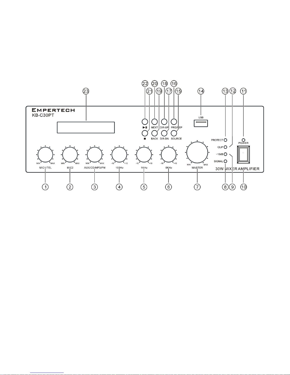
Functional components
1. MIC1/TEL Volume
18.DIR-UP
2. MIC2 Volume
19.Back/Backward
3. AUX/CD/MP3/FM Volume
20.Next/Forward
4. Bass 150Hz
21.Play/Pause
5. Middle 1KHz
22.Stop
6. Treble 6KHz
23.LCD Display
7. Master Volume
8. Signal LED
9. -10dB LED
10. Power Switch
11. Power LED
12. Clip LED
13. Protect LED
14. USB Input
15. MP3/AM/FM/CD Selection
16.PRG/REPEAT
17.DIR-DOWN
Front Panel
2

Rear Panel
1. Appliance inlet
2. Fuse used in inlet
3. Ground screw
4. Manual Priority terminals
5. Speakers output terminals
6. AUX Input
7. CD Input
8. AUX/CD Selector Switch
9. AUX Music on Hold Volume Control
10. MIC2 Input-unbalanced
11. MIC1/ Telephone Paging Input-Balanced
12. MIC1/Telep. Paging gain control
13. AM Ant
14. AUX Music on Hold output
15. FM Ant
3

Operation
Equalizer Controls
Three different controls for three frequency bands. Those volume controls will increase or decrease bass and
treble or add some presence to the sound.
Manual Priority Terminals
These two terminals, when shorted, will mute incoming signal from AUX and CD inputs, thus giving priority to the
Telephone Paging and Microphone. These are especially useful when a table microphone with switch is part of
the installation.
Connectios
Microphone1
The microphone inputs use DIN-5 jack and are balanced. Priority operation can be
obtained by using the din sockets.(see priority connection)
Balanced operation
Pin 1 (H) Signal +(live)
Pin 2 (G) Screen(GNG)
Pin 3 (C) Signal- (return)
Pin 4 (P) Priority terminals
Unbalanced operation
Pin 1 (H) Signal +
Pin 2 (G) Screen(GNG)
Pin 3 (C) Short to pin 2
Pin 4 (P) Priority Control
4

Microphone2
Mic2 input is a Unbalanced standard 1/4〃mono jack on the rear panel .
Wiring is as follows
AUX/CD Connection
AUX/CD input is two phono sockets .These inputs are configured as AUX Or CD inputs
MP3 /TUNER Selection
The built-in MP3 /TUNER can work proper when switching to CD,MP3,Tuner on rear panel.
Equalizer Controls
Three different controls for three frequency bands. Those volume controls will increase or decrease bass and
treble or add some presence to the sound.
5

6
Manual Priority Terminals
These two terminals, when shorted, will mute incoming signal from AUX and CD inputs, thus giving priority to
the Telephone Paging and Microphone. These are especially useful when a table microphone with switch is
part of the installation.
Speaker Terminals
These terminals are offering 3 low voltage outputs 4Ω, 8Ω, 16Ω depending on your speaker combination. A
70V/100V commercial output is also available. Please note that one wire only should be connected to COM
screw and one wire to the selected impedance or voltage. Multiple combinations cannot be done at the
output level.
Four different types of connections are provided. The low
impedance section: 4Ω, 8Ω, 16Ω is designed for a small
amount of speakers to be connected to your amplifier. The
100V section is especially designed for a multiple speaker
distribution. When using the 100V output, speakers have to
be equipped with 100V transformer. The maximum amount of
speakers to be placed on your distribution line is in relation to
the power allocated to each speaker. The total wattage set on
the secondary side of the transformers on your speaker line
must not exceed the maximum RMS output power: 30W or
60W. Failure to respect this may cause permanent damage to
the amplifier.
Microphone Input
This ¼ ’’ jack is a two conductor unbalanced microphone input. If you wish to use a low impedance
microphone on a balanced line with a long cable, we recommend that you use an AM-15 adaptor to do so. If
you choose to use a Table Top microphone with an enunciator switch, keep in mind that the switch should be
connected to the two priority terminals.

7
Music on Hold
This output will feed music on your telephone system for people waiting to be answered. A dedicated input
should be available on your telephone system. Please refer to a qualified technician if you can’t identify this
input. Outgoing signal should be connected to G and H. Volume control is located next to the terminal in
order to provided proper level of music on the phone system.
Telephone Paging Input
This special input (terminals 1 and 3) will allow you to page in your PA system using your own telephone set.
Pin 2 is Ground and Pin 4 is for manual priority switching. Any signal going through Pin 3 with automatically
triggers the priority system without any manual intervention. At the end of the announcement, the system will
return to its normal operation. A Gain control is located next to the input in order to increase incoming
volume if necessary. Final adjustment will be made with the Tel Paging volume control located on front panel.
Recommandations
Keep your amplifier away from excessive humidity, dust or grease. This unit has sensitive components that can
be affected in a difficult environment. If, at one point during its usage, the fuse on the AC line needs to be
changed make sure that the replacement is of the same value. It is important that you try to identify the
reason for this failure. This will most likely prevent further damage to your amplifier. Any service work on this
unit should be performed by a qualified technician.

8
Specifications
KB-C30PT
KB-C60PT
Output Power
30W
60W
Fuse
T1AL 250V
T1.6AL 250V
THD at Rated Power
<2.5%
Speaker Outputs
4Ω, 8Ω, 16Ω, 70V/100 V( 70V/100V choose 1 of these 2 )
Frequency Response
100Hz – 20 kHz
MIC2 Input
3mV @ 600 Ω
AUX Inputs
200mV @ 50 KΩ
CD Inputs
400mV @ 50 KΩ
Telephone Paging/MIC1 Input
6 – 700 mV
Music on Hold Output
1W max@ 32Ω
Sig/Noise Ratio, Mic
>65 dB
Sig/Noise Ratio, AUX/CD
>75 dB
Tone Controls
±12 dB
AC Power
~230V / 50 Hz
FM TUNER
87~108 mHz
AM TUNER
522~1611 kHz
Dimensions
270(W)x90(H)x 260 (D) mm
Weight
3.7kg
4.7kg
Gross Weight
4.8kg
5.8kg
Model

9
Block Diagram


 Loading...