

Page 1
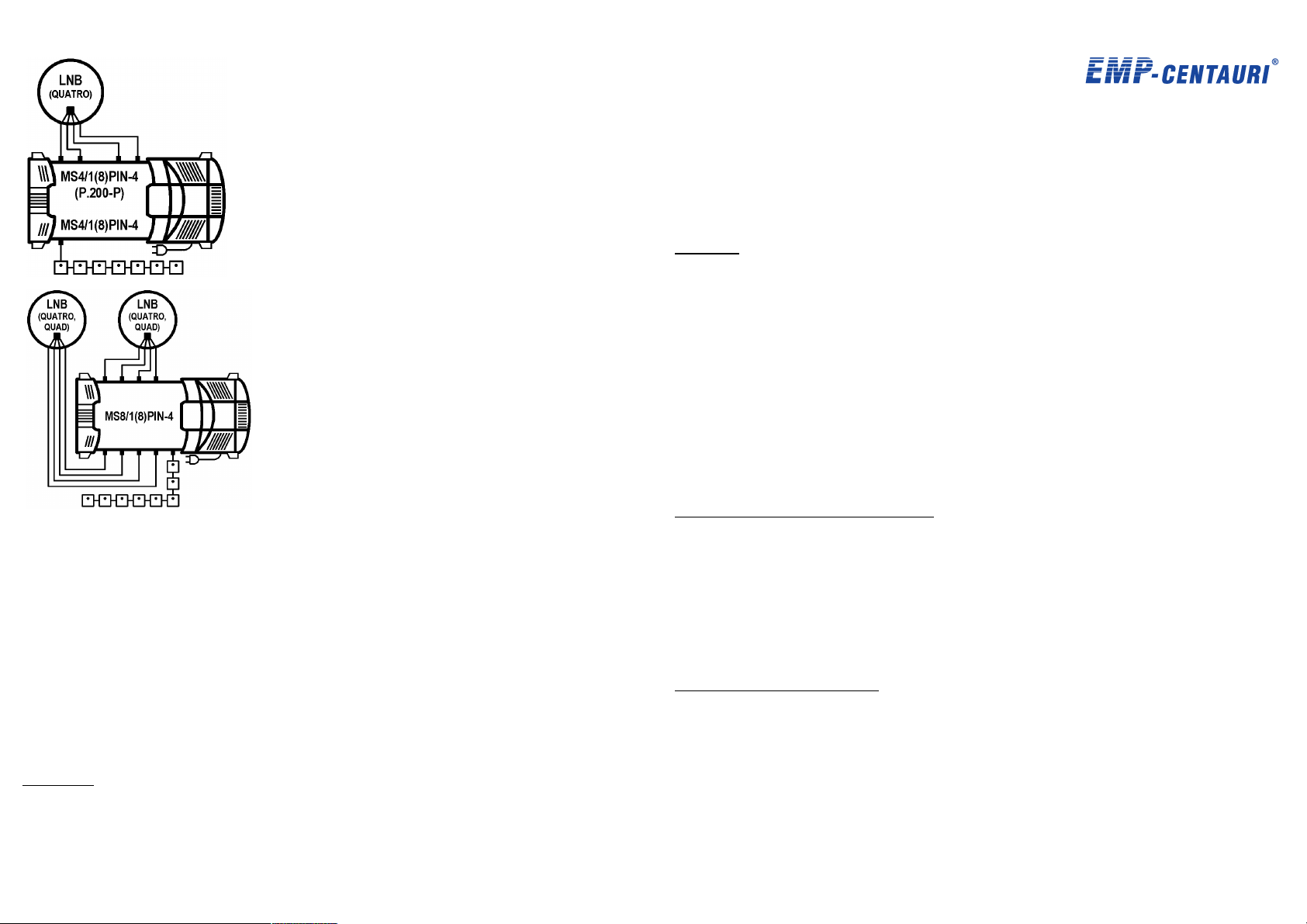
standalone Unicable
1 z 8
8 z 8
multiswitches for
distribution of satellite
signals from 1 satellite
position (4 polarities) for
8 users
standalone Unicable
multiswitch for
distribution of satellite
signals from 2 satellite
positions (8 polarities)
for 8 users
TM
TM
Instruction Manual 1/003030 B
MS5/4PIU-4
MS5/6PIU-4
MS5/12PIU-5
MS5/16PIU-5
MS5/8PIU-4
Dear Customer,
congratulations on the purchase of the EMP-Centauri product. Before its installation and putting
into operation, read carefully the entire operation manual. Keep the purchase and rework (if any)
records for future need.
Content
1 Field of Application, Warranty 1
2 Technical Specifications 1
3 Product Takeover 3
4 Product Storing and Installations 3
5 Product Connection 3
6 Product Settings 4
7 Safety 4
8 Product Maintenance 5
9 Troubleshooting 5
10 Symbols Explanation 6
11 Wiring Diagrams 6
12 EMP-Centauri Related Products 7
13 Contact 8
13 Contact
EMP-Centauri s.r.o.
5. kvetna 690
339 01 Klatovy 4
Czech Republic
tel: (+420) 376 314 852
fax: (+420) 376 314 367
[email protected]
www.emp-centauri.eu
1 Field of Application, Warranty
The product is designed for the distribution of satellite (SAT), terrestrial (TERR); TV and radio
signals. We recommend the device to be installed and serviced by the qualified technician.
EMP-Centauri's PROFI CLASS products are covered under 4 (four) years warranty from the
date of purchase. The warranty shall not apply to the product used for other than the specified
purpose. The user will be responsible for injury or material damage which may arise in
consequence of any product use in contradiction with the manual. It is prohibited to dismantle
the product and make any interventions in it. Repairs or any interventions in the product may be
performed only by EMP-Centauri company, or other companies authorized by EMP-Centauri.
2 Technical Specifications
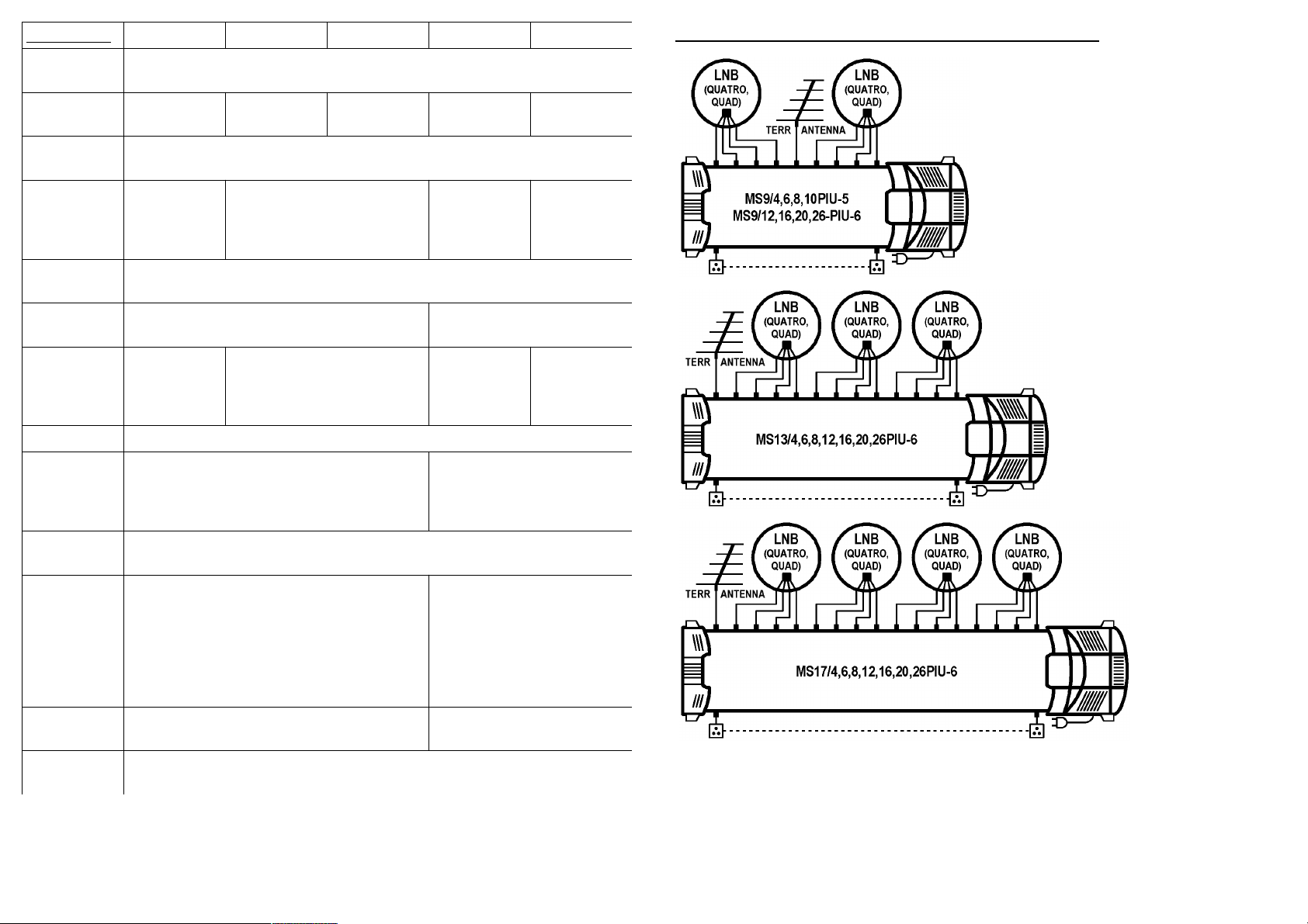
The products are standalone multiswitches for distribution of terrestrial and satellite signals from
1 satellite position (4 polarities) for 4 (MS5/4PIU-4), 6 (MS5/6PIU-4), 8 (MS5/8PIU-4), 12
(MS5/12PIU-5) or 16 (MS5/16PIU-5) users. Multiswitches are controlled from receiver by
analogue commands. It is enabled to switch on active or passive mode of terrestrial band.
Multiswitches are compatible with quad LNB. Terrestrial input can supply terrestrial antenna
preamplifier with DC voltage, the supply is electronically protected against short-circuit.
Multiswitches are powered from internal power supply P1U27.
Page 2
Specification MS5/4PIU-4 MS5/6PIU-4 MS5/8PIU-4 MS5/12PIU-5 MS5/16PIU-5
7 z 8
2 z 8
Number of
Inputs
Number of
Outputs
Frequency
Range
Insertion
Loss (avg)
Isolation
(min)
Maximum
Input level*
Maximum
Output
Level*
Control analogue commands
Current
Consumption
Current from
Terr. Input
Power
Consumption
Dimensions
(w,d,h)
Temperature
Range
* TERR: EN 50083-3/60dB IMA3 [dBuV]; SAT: EN 50083-3/35dB IMA3 [dBuV]
5
4 6 8 12 16
TERR 5-862 MHz (pas), 40-862 MHz (act), SAT 950-2300 MHz
TERR 2/19 dB
(act/pas),
SAT 3 dB
20 dB
TERR 93/100 dBuV (act/pas),
SAT 100 dBuV
TERR 91/81
dBuV
(act/pas),
SAT 97 dBuV
40mA (18 V DC) from each satellite receiver,
240 mA / 18 V DC (act) or 160 mA / 18 V DC
(pas) from power supply
100 mA max (12 V DC)
6.0 W / 4.0 W (act/pas) + consumption of devices
connected to inputs (LNB, terrestrial antenna
preamplifier, etc.), maximum consumption of
multiswitch and connected devices must not
exceed maximum output power of power supply
26.5 x 15.2 x 8.7 34.5 x 15.2 x 8.7
-30°C - +70°C
TERR 3/20 dB (act/pas),
SAT 4 dB
TERR 90/80 dBuV (act/pas),
SAT 96 dBuV
TERR
7gain/21 dB
(act/pas),
SAT 0 dB
TERR 85/100 dBuV (act/pas),
SAT 90 dBuV
TERR 92/79
dBuV
(act/pas),
SAT 90 dBuV
45 mA (18 V DC) from each
satellite receiver, 360 mA / 18
V DC (act) or 210 mA / 18 V
DC (pas) from power supply
9.0 W / 5.0 W (act/pas) + consumption
of devices connected to inputs (LNB,
terrestrial antenna preamplifier, etc.),
maximum consumption of multiswitch
and connected devices must not exceed
maximum output power of power
supply
TERR
6gain/22 dB
(act/pas),
SAT 0 dB
TERR 91/78
dBuV
(act/pas),
SAT 90 dBuV
avg - average value, there is tolerance of ±3 dB in specified range
min - minimum value
act/pas - active/passive mode of terrestrial band
12 EMP-Centauri's PROFI CLASS Related Products
standalone
multiswitches for
distribution of
terrestrial and satellite
signals from 2
satellite positions (8
polarities) for 4-26
users
standalone
multiswitches for
distribution of
terrestrial and satellite
signals from 3
satellite positions (12
polarities) for 4-26
users
standalone
multiswitches for
distribution of
terrestrial and satellite
signals from 4
satellite positions (16
polarities) for 4-26
users
Page 3
exceeds the specifications, see section 2 Product Specifications. The next cause can be
6 z 8
3 z 8
the overheating of product in consequence of wrong installation, see section 4 Product
Storing and Installation. Disconnect the product from the power grid, remove the cause,
and re-plug the product into the power grid after a few minutes again.
If the failure cannot be removed, please contact your distributor.
10 S ymbols Explanation
certificate of conformity
for indoor use only
DC power supply
grounding
Power Supply Specifications P1U15
Input Voltage 90-265 V AC, 50/60 Hz
Output Voltage 18 V DC
Maximum Output Current 0.8 A (18 V DC)
Maximum Output Power 15 W
Efficiency 75% min
Dimensions (w,d, h) 12.6 x 15.2 x 8.7 cm (power cord length 130 cm)
Temperature Range -30 - +70 °C
3 Product Takeover
Make sure that the product is not damaged and following accessories are enclosed:
• 75 Ω loads for the impedance matching of unused outputs (2 pcs, others can be ordered
from EMP-Centauri, code 1000066).
In the case of damage or missing accessories please contact your dealer.
class II device
fuse protected
safety transformer
According to EU directive, electric and electronic devices which are identified by
one of the following symbols must not be disposed of together with municipal
waste. When disposing of the old device, use local waste collection and separation
systems.
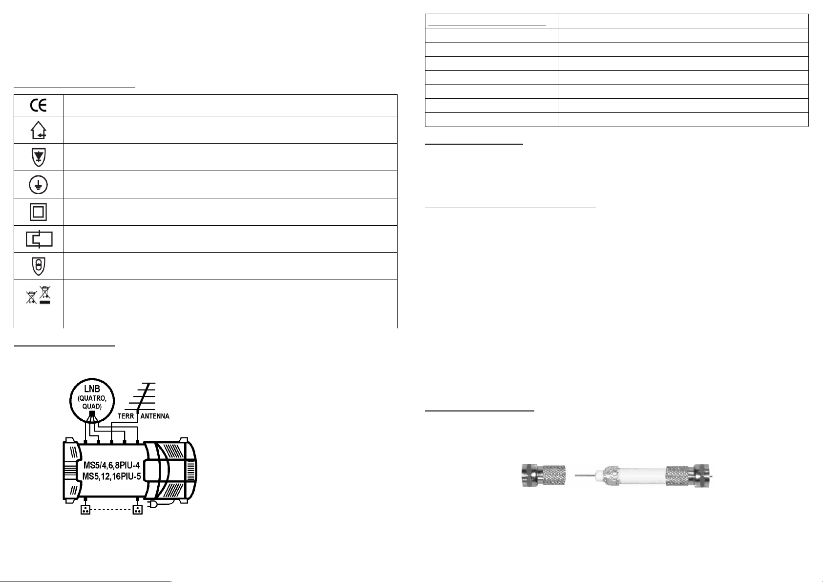
11 Wiring Diagrams
4 Product Storing and Installation
The product must not be stored and installed
• in the place with excessive humidity,
• in the place with dropping or running water,
• in the place with high dust pollution, mechanical vibrations or impacts,
• in the place out of temperature limits specified in the section 2 Technical Specifications,
• close to heat sources (radiators or air ventilators, direct sunshine etc.),
• in the reach of children.
Fix the product firmly on a wall or another hard and inflammable surface with screws and
dowels. The mains socket must be placed near the product. The mains socket and plug must
be easily available.
• The product shall be in no case held only by the connected cables.
• Ensure the free space for the air circulation (space on sides and bellow the product
should be at least 20 cm and the space over its top at least 50 cm).
• Do not cover the product (with curtains etc.).
• Do not place any containers with liquids (vases, glasses etc.) or naked flame sources
(lighted candle etc.) on the product or near the product.
5 Product Connection
Connect the product in accordance with this manual and valid regulation. Use high-quality 75 Ω
coaxial cable designed for satellite reception. Mount the F connectors (screw, crimp or compress
type) on the ends of coaxial cables, in the case of using the screw F connectors proceed according
to the following picture and instructions:
1. Remove the outer coaxial cable coating in the length of approx. 15 mm.
2. Roll up the metal shielding braid and the shielding foil underneath and cut the shielding
with scissors to approx. 5 mm.
3. Remove approx. 10 mm of the inner plastic insulation (approx. 5 mm of the insulation
remains in a place).
Page 4
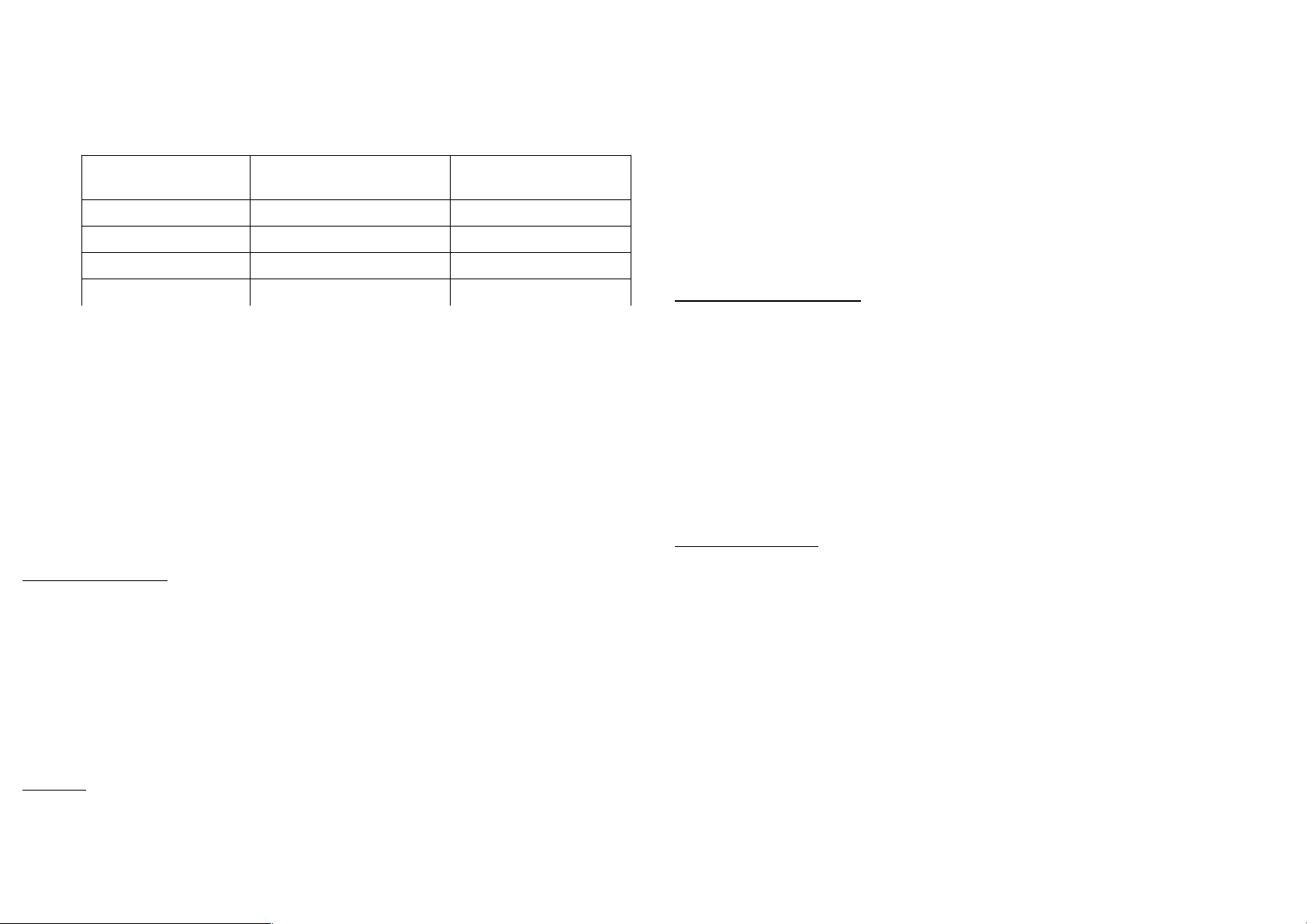
4. Carefully screw the F connector on the cable end until the plastic insulation levels with
4 z 8
5 z 8
the F connector opening.
5. Check there is no short between the inner conductor of coaxial cable and F connector.
The coaxial cables shall not be broken, the minimum bending radius should be 5 cm. Connect the
F connectors into the F sockets of product and fasten them with an appropriate force.
• Connect input F sockets marked A-D with convertor (LNB) outputs according to the
next table:
marking of F socket of
multiswitch
A V/L or 12V/0kHz any output
B H/L or 18V/0kHz any output
C V/H or 12V/22kHz any output
marking of outputs of
quatro LNB
marking of outputs of
quad LNB
The product works with the AC voltage, see section 2 Technical Specifications. Make sure,
that the local AC voltage corresponds to the operating voltage of product.
No objects can be placed on the mains cord for prevent its damage or break. No hot objects
should touch the mains cord.
While disconnecting the product from power grid, never pull the mains cord but the mains
plug to prevent the mains cord damage. Pay attention that the mains plug holds tight in the
mains socket. Loose mains plug or mains socket means the danger of fire.
Never disassemble the product connected to the power grid, you risk the danger of electrical
shock.
Never work on the wiring (including satellite and terrestrial receivers, TVs) during or
before a storm. A lightning stroke into the antenna may cause dangerous overvoltage in the
product metallic parts.
The product should be disconnected from the wiring immediately if it gets into contact with
liquids (dropping water, spilled drinks etc.).
D H/H or 18V/22kHz any output
• Connect input F socket marked TERR IN with output of terrestrial antenna, eventually
with output of terrestrial antenna with terrestrial antenna preamplifier.
• Connect output F sockets marked 1 to actual number of outputs of multiswitch with
other components in distribution system (satellite receiver, terrestrial receiver, wall
socket etc.).
• Connect the mains plug into the mains socket with voltage according to section 2
Technical Specifications.
• Connect connector marked with grounding symbol with protective earthing conductor,
see section 10 Symbols Explanation.
If some of outputs are not used, it is appropriate to terminate them with 75 Ohm loads. If not
terminated, insertion loss curve in terrestrial band may be rippled.
The wiring examples are shown in the section 11 Wiring Diagrams or at the website www.empcentauri.eu.
6 Product Settings
For all SAT inputs, it is possible to change level of signals by means of attenuators in 15 dB
range; the minimum attenuation is in clockwise stop position, the maximum attenuation is in
counterclockwise stop position (for terrestrial input switching to passive mode, see below). Set
attenuators very gently, do not turn them behind stop positions by force.
Active and passive mode of terrestrial band can be selected by turnable switch, passive mode is
selected by turning the switch to counterclockwise stop position. The return path is available in
the passive mode.
If input F socket marked TERR IN is in short connection or maximal allowed current is exceeded
(see section 2 Technical Specifications), the voltage decreases down to 0 V. Quality of signals is
not affected however.
7 Safety
Due to security reasons the product and wiring in which the product is connected, must be
grounded properly. Use the earthing terminal identified with the symbol of grounding to
ground the product. Make sure the antennas are grounded properly.
Connect all devices to power grid only after all connections are finished and checked.
8 Product Maintenance
Always disconnect the product from the power grid and wiring before performing any
maintenance of the product. If you have to enter places with a risk of fall, pay attention to
your safety.
Use only dry cloth to clean the product and do not use any liquid agents.
Coaxial cables installed outdoors should be replaced once in a few years. Unscrew all F
connectors and clean connector contacts, resp. shorten the coaxial cable by approx. 2 cm, every 2
years.
Check the state of power supply and its mains cord periodically. If the mains cord or the
mains plug of product is damaged, it must be replaced by manufacturer or qualified
technician to prevent any dangerous situation. Let the product serviced if the housing of
power supply is damaged.
If not used for long time, disconnect the product from the power grid.
9 Troubleshooting
Always disconnect the product from the power grid before working on product, otherwise
you risk the electric hazard. Pay attention to your safety if you have to enter places with a
risk of fall.
In the case the product does not work and LED of power supply is on:
• Check if the terrestrial and satellite antennas are correctly fixed, optimally set and
connected to the product, satellite and terrestrial receivers turned on, plugged on and
correctly set.
• Check the connector connections. The inner conductor of coaxial cable must be in
contact with the inner conductor of F socket and the shielding of coaxial cable with F
connector. Replace broken or interrupted coaxial cable.
In the case the product does not work and LED of power supply is off or blinks:
• Check that the product is connected to the power grid with AC voltage. If not, connect
the product to the power grid with correct AC voltage.
• Disconnect the product from the power grid and check that there is no short-circuit on
the input satellite coaxial cables, which prevents the power supplying of LNBs. If yes,
remove short-circuit and re-plug the product into the power grid again.
• The power supply can fail temporarily in case of overload or overheating. The cause can
be current consumption of devices connected to the satellite inputs of product which
 Loading...