

Page 1
Part Number
Serial Number(s)
1030085xxx
All
Rev
Rev By
Date
Description of Change
Approved By
C
BF
10/30/13
Formatting, Orientation, Checklist
ECN3149
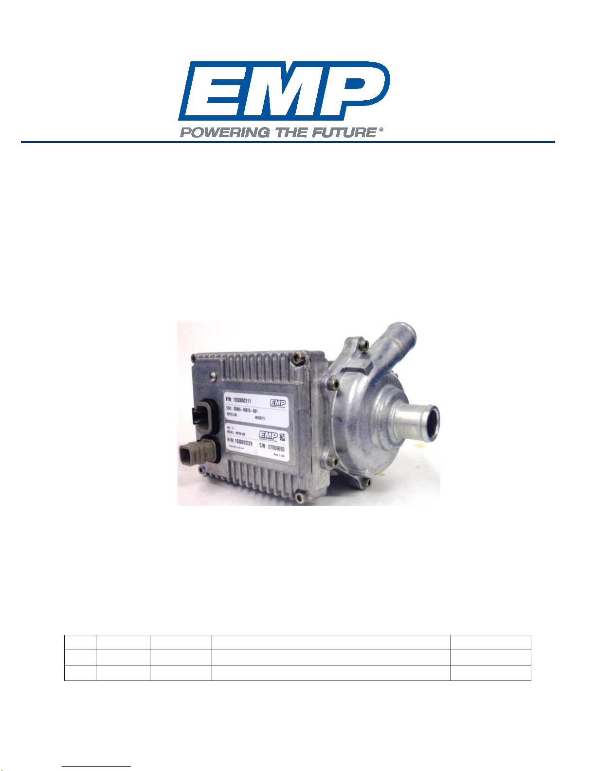
WP29 and WP32 Electric Water Pump
Installation Manual
and
Installation Approval Documentation
This manual is effectiv e for aftermarket and OEM installations
of the following part and serial numbers:
1030002xxx
A MPL/BF 4/9/13 Original Release ECN2805
9970002273 Rev_C - 5/13/2014 © 2013 EMP, Inc 1
All
Page 2

Engineered Machined Products Inc.
2701 North 30th Street
Escanaba, Michig an 49829
Phone: 906-789-7497
www.emp-corp.com
Product Overview
The WP29 and WP32 are electrically powered fluid pumps available in 12 volt DC and 24 volt DC
configurations. The pump is available with carbon steel, or stainless steel shafts for fluid compatibility. Proper
installation of the pump will help ensure the performance and reliability of the electric pump while reducing the
risk of damage to other components in the system.
This document provides a check list to confirm that the pump and the installation of the pump fall within the
hardware and operational capabilities of the pump. If there are parameters outside the normal application,
additional information will be required for EMP Engineering to approve the installation or warranty will be void.
Use the Installation Approval check sheet located in Appendix B to submit
installation inf ormat ion to EMP for approval.
The information contained in this manual is updated periodically. While great care is taken in compiling the information contained in this m anual,
Engineered Machined Products, Inc. cannot assume liability for losses of any nature arising from any errors and/or omissions.
The information and specifications contained throughout this manual are up to date at the time of publication. Engineered Machined Products, Inc.
reserves the right to change the content of this manual at any time without notice.
© 2013 EMP, Inc 2
Page 3

Table of Contents
Product Overview ............................................................................................................................. 2
Safety .................................................................................................................................................... 4
Warnings, Cautions & Notes ............................................................................................................. 4
Product Safety Warnings .................................................................................................................. 4
Purpose................................................................................................................................................. 5
Development Engineer Responsibilities ................................................................................................ 5
Specifications ........................................................................................................................................ 6
Dimensions ....................................................................................................................................... 6
Hole Locations/Bolt Spacing ............................................................................................................. 6
Material Listing of Major External and Fluid Contacting Parts .......................................................... 7
Performance ......................................................................................................................................... 9
Pump Performance Curves .............................................................................................................. 9
Pump Limitations ................................................................................................................................ 10
Temperatures ................................................................................................................................. 10
Vibration ......................................................................................................................................... 10
Environment ................................................................................................................................... 10
Orientation ...................................................................................................................................... 10
Inlet and Outlet Pressures .............................................................................................................. 11
Fluid Level ...................................................................................................................................... 12
Approved Coolants ......................................................................................................................... 12
Supplementary Coolant Additives (SCA) ........................................................................................ 12
Plumbing ............................................................................................................................................. 13
Recommended Plumbing ............................................................................................................... 13
Electrical Specifications and Requirements ........................................................................................ 14
Schematics ..................................................................................................................................... 15
Mating Connectors .......................................................................................................................... 15
Wiring .................................................................................................................................................. 16
Wire Sizing ..................................................................................................................................... 16
Recommended Wiring Practices..................................................................................................... 16
Installation ........................................................................................................................................... 17
Orientation Specific ......................................................................................................................... 17
Dual Orientation .............................................................................................................................. 18
Incorrect Pump Orientation and Reasons ....................................................................................... 18
Physical Inspection ............................................................................................................................. 19
Troubleshooting .................................................................................................................................. 20
EMPower Connect™ Service Tool ...................................................................................................... 20
Appendix A, WP29 and WP32 Installation Testing ............................................................................. 21
Equipment Required for WP29 and WP32 Data Collection ............................................................ 21
Inlet Pressure Measurement Test Procedure ................................................................................. 22
Test Data Log Sheet ....................................................................................................................... 24
Appendix B, WP29 and WP32 Installation Approval Registration and Check Sheet ........................... 26
Installation Approval # .................................................................................................................... 26
Product Installation Questionnaire .................................................................................................. 27
© 2013 EMP, Inc 3
Page 4
Safety
Safety
Warnings, Cautions & Notes
Three types of headings are used in this manual to stress your safety and safe operation of the WP29.
They appear in the text as follows:
WARNING:
THIS SYMBOL IS USED TO MAKE YOU AWARE OF AN UNSAFE CONDITION, HAZARD, OR PRACTICE THAT
CAN RESULT IN PERSONAL INJURY OR DEATH.
CAUTION:
THIS SYMBOL IS USED TO ALERT YOU TO A CONDITION OR PRACTICE THAT CAN CAUSE DAMAGE TO
THE WP29 AND WP32 OR THE VEHICLE, OR BOTH.
NOTE: Is used to provide additional information that requires special attention by the technician.
Product Safety Warnings
EMP cannot anticipate every possible circumstance that might involve a potential hazard. The safety messages in this
document, in related manuals, and on the product are therefore not all inclusive. If a tool, procedure, work method, or operating
technique that not specifically recommended by EMP is used, you must satisfy yourself that it is safe for you and for others. You should
ensure that the product will not be damaged or be made unsafe by the operation, maintenance, or repair procedures that you choose.
Ensure that all safety message and information messages are read and understood before installation, maintenance, or any
repairs are performed. The person who services the product may be unfamiliar with many of the systems on the product. It is
important to use caution when service work is performed. Knowledge of the vehicle system and operation are important before the
removal or disassembly of any component.
Make sure the vehicle is in neutral, the parking brake is set, and the wheels are blocked before doing any work or diagnostic
procedures on the WP29 and WP32, or vehicle.
Disconnect the main negative battery cable and/or switch the battery disconnect switch to the OFF position first before
installation or servicing.
Use extreme caution when working on systems under pressure (i.e. coolant, hydraulic fluids, air, etc…)
Make sure the work area is ventilated and well lit.
Make sure charged fire extinguishers are in the work area.
Reinstall all safety guards, shields, and covers after servicing the vehicle.
Make sure all tools, parts, and service equipment are removed from the engine compartment and vehicle after all work is done.
Do not apply power to the pump without fluid since most pumps are programmed to start when power is applied and the pump
seal will be damaged if run dry.
If CAN or Serial TTL control is not used the 6 pin DTM connector must be blocked off to prevent entry of water or dirt which will
result in damage to the pump. A block off plug EMP P/N 3250001030 can be purchased or one can be fabricated from the Deutsch
parts listed in the table on page 12
© 2013 EMP, Inc 4
Page 5

Purpose
Purpose
The purpose of the WP29 and WP32 installation manual is to present information related to the
pump’s dimensions, electrical specifications, flow and pressure capabilities, coolant guidelines,
recommended plumbing, and system testing. This manual also outlin es th e WP29 and WP32
limitations that should be recognized and adhered to.
Development Engineer Responsibilities
The organization responsible for incorporating the WP29 and WP32 pump into any system must read
and understand the requirements and specifications as explained in this manual. At any time during
system development, EMP will participate in a design review if requested. Prior to production release
of any system incorporating the WP29 and/or WP32, please take the time to fill out the included
product installation registration form and e-mail to [email protected].
EMP engineering will review the intended installation and will contact you if there are any issues seen
in the information provided. It is up to the design engineer to ensure that all requirements are met;
failure to do will void product warranty.
© 2013 EMP, Inc 5
Page 6
Specifications
Specifications
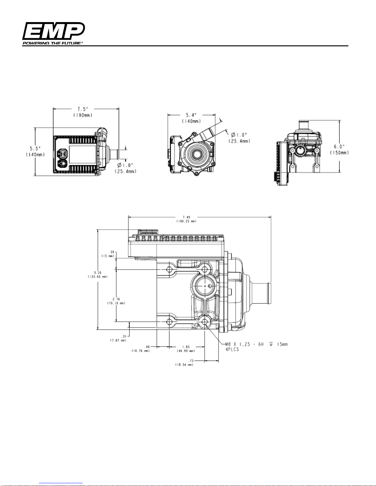
Dimensions
Hole Locations/Bolt S pa ci ng
© 2013 EMP, Inc 6
Page 7
Specifications
Material Listing of Major External and Fluid Contacting Parts
Item Quantity Description Material Fluid Contact
1 1 Cover Cast Aluminum (413)
2 1 Housings Cast Aluminum (413) YES
3 10 Bolt 18 – 8 Stainless Steel
4 1 Volute Cast Aluminum (413) YES
5 1 Impeller (Internal) 304 Stainle ss St eel YES
6 1 Shaft 1020 Carbon Steel YES
7 1 Product Label M - 714
8 2 Connector Dupont Zytel Nylon 70G33L
NOTE: SAE 440 Stainless Steel Shafts are offered as an option on EMP WP29 and WP32 Pumps. Contact customer
service for part number information.
© 2013 EMP, Inc 7
Page 8
Specifications
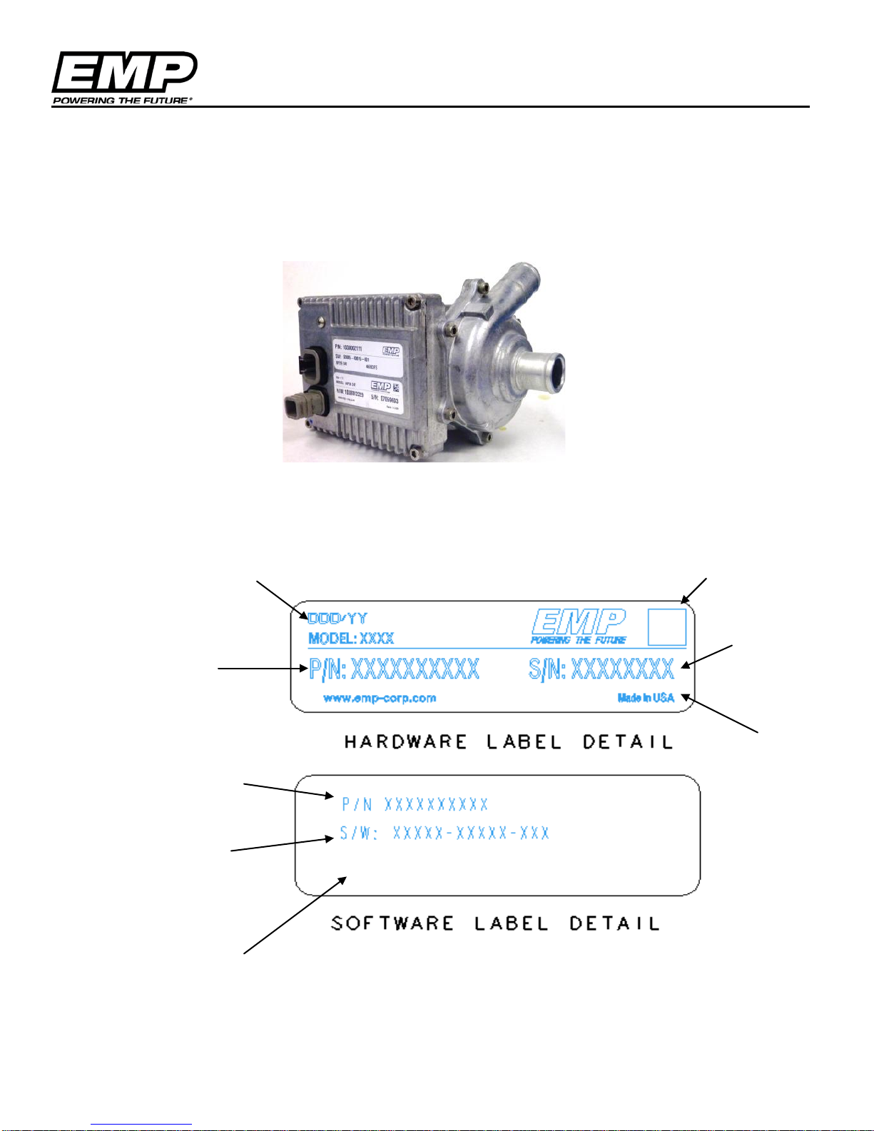
Date Code
Serial Number
Country of Origin
Hardware Part
Bar Code
EMP Programmed
Software Calibration
Customer optional
Identification
The product identification labels are attached to the controller housing next to the electrical interface of the
pump. The pump hardware part and serial numbers are located on the upper label. The lower label identifies
the Programmed Assembly number and the associated control software as the pump leaves the manufacturing
facility. The EMP service tool can be used to confirm the pump software should calibration changes be
required and new identification tags issued.
Label Details
Number
Assembly Number or
Customer Part Number
Number
information
© 2013 EMP, Inc 8
Page 9
Performance
Flo w -vs- St at ic Pressure Rise
WP29 12 volt Pump
0
5
10
15
20
25
30
0 5 10 15 20 25 30
Flow (gpm)
Pump Rise (psi)
14V Ful l 4000
3500
3000
2500
2000
1500 1000
.
Static Pressure Rise -vs- Flow
WP29 - 24 volt pump
0
5
10
15
20
25
30
0 5 10 15 20 25 30 35
Flow (gpm)
Pump Rise (psi)
WP29 24V (1000)
WP29 24V (2000)
WP29 24V (3000)
WP29 24V (4000)
WP29 24V (4500)
WP29 24V (max spee d )
.
WP32 and WP29 -12V
WP32 and WP29 -24V
Performance
Pump Performance Curves
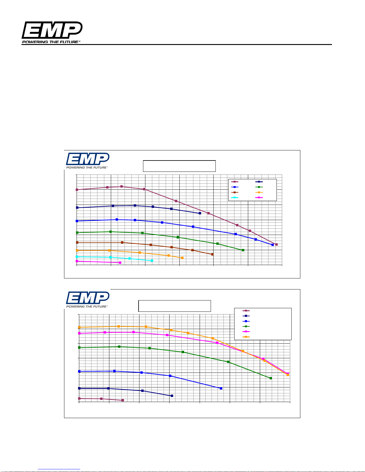
The pump performance curves shown in the illustrations below outline the maximum capability of the pump at
maximum speed of the pump. Following the installation guidelines will result in peak performance matching
the illustrated operation. Pump speed reduction will reduce the output capability.
The static pressure curve represents the pressure rise across the pump for a given flow. If the inlet pressure of
the pump is negative, the outlet pressure of the pump is reduced by the inlet suction. Be aware of this situation
in systems with little or no head pressure on the system.
© 2013 EMP, Inc 9
Page 10
Limitations
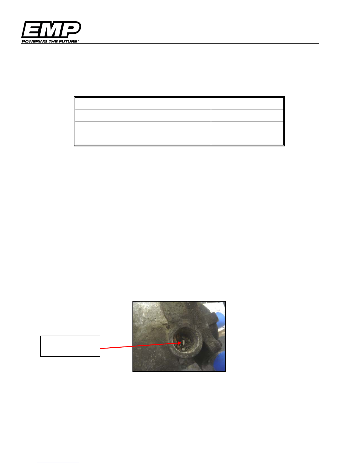
Debris in weep
hole region
Pump Limitations
Temperatures
Table 1: Temperature Limitations
Maximum Fluid and Ambient Operating Temp
Minimum Fluid and Ambient Operating Temp
Maximum Ambient Storage Temp
Minimum Ambient Storage Temp
* If the intended application fluid temperature exceeds 95°C, installation must be
reviewed and approved by EMP to ensure warranty coverage. See Appendix A
for the Installation Approval checklist.
203°F (95°C)*
-40°F (-40°C)
257°F (125°C)
-40°F (-40°C)
NOTE: Over-temperat ur e Pr otection
If the internal electronics operating temperature exceeds 266°F (130°C) the pump will shut off and stay off until the
°
temperature drops to 257
electronics temperature threshold.
F (125°C). At 95°C fluid temperature the pump controller is operating near the 130°C
Vibration
Vibration exceeding the EMPTS009 profile can shorten pump life, potentially leading to PCB and motor shaft
failures. If you are unsure of your vibration profile for a given installation please contact EMP to ensure
warranty coverage.
Environment
Environment cleanliness is crucial to pump life. The WP29 and WP32 are certified with an IP67 rating but
debris collection in the weep pocket can lead to premature seal failure (See figure below). Shielding may be
required to ensure debris does not enter the weep hole. If you have any questions regarding your installation
contact EMP to ensure warranty coverage.
Orientation
Each pump part number has a specified and approved orientation. If the pump is not properly installed several
failure modes could potentially result. Please reference the Pump Orientation section of this document for
installation guidelines. If you have any questions regarding pump orientation please contact EMP to ensure
warranty coverage
© 2013 EMP, Inc 10
.
Page 11
Limitations
WP29 Pump Inlet Pressur e
-10
-8
-6
-4
-2
0
2
0 1000 2000 3000 4000 5000
WP29 Pump Spee d ( r pm )
Pump Inlet Pressur e ( psi )
Inlet A Inlet B Inlet C LIMIT
Operation in this Range
WP32 and WP29 –Pump Inlet Pressure
Inlet and Outlet Pressures
Inlet Pressure/Configuration
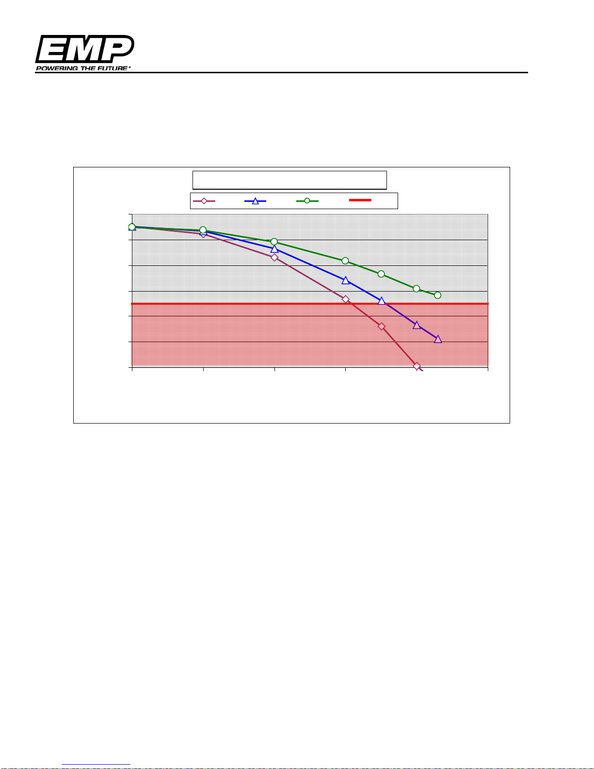
• The WP29 and WP32 pumps must maintain an inlet pressure greater than -5 psi (-35kPa gauge) at
the set WP29 and WP32 operating speed under all operating conditions
Is Not Allowed
In the WP29 and WP32 Pump Inlet Pressure Map, three inlet configurations are illustrated. “Inlet A”
configuration represents an inlet that is very restrictive, and any pump operation above 3000 pump rpm
will violate the minimum inlet pressure requirement. The configuration will be forced to have a 3000
rpm pump speed limit. “Inlet B” is also restrictive, and will require the WP29 and WP32 pump speeds
to be limited to 3500 rpm, where “Inlet C” remains in the safe operating zone for all measured pump
speeds and has no special limitations.
If the application has low outlet restriction, the pump is current limited and may not be able to reach the
anticipated pump speed. This speed limitation is a result of the motor controller protecting the
electronics from a condition where excessive heat may build up in the controller.
© 2013 EMP, Inc 11
Page 12
Limitations
Fluid Level
CAUTION: DO NOT RUN THE PUMP WITHOUT FLUID PRESENT. IF RUN DRY EVEN FOR A SHORT
PERIOD THE SEAL WILL BE DAMAGED.
Approved Coolants
Heavy Duty Engines using Fully Formulated Coolant: Reference ASTM D6210 -10 for coolant quality and
maintenance schedules. Test method references are listed in this specification
Light Duty Partial Formulated Coolant: Reference ASTM D3306 for coolant quality and maintenance
schedules.
Based on field testing and experience, the WP29 and WP32 are compatible with the following coolant types:
1. Ethylene Glycol
2. HOAT ( Hybrid Organic Acid Technology)
3. OAT (Organic Acid Technology)
4. Propylene Glycol
NOTE: - Use distilled water t o dilute c oolant or use pre-mix coolant
Supplementary Coolant Additives (SCA)
Coolant additives are allowed with the WP29 and WP32 water pump. The additive must be compatible with
the base coolant and all contact surfaces of the pump. The additive concentration must be within the additive
manufacturer’s specification. Damage to the WP29 and WP32 or the system will not be warranted if the
additive is not compatible with the base coolant or the concentration is outside manufacturer
recommendations.
CAUTION: CONTACT CUSTOMER SERVICE TO VERIFY THAT COOLANTS NOT LISTED ABOV E ARE
COMPATIBLE WITH PUMP COMPONENTS AND COMPLETE THE INSTALLATION APPROVAL FORM. WHEN USING
A COOLANT THAT IS NOT APPROVED, THE INSTALLATION MUST BE EMP APPROVED
CAUTION: USE OF “STOP LEAK” STYLE SYSTEM ADDITIVES ARE NOT APPROVED
CAUTION: MIXING OF COOLANTS CAN CAUSE PROBLEMS WITH THE COOLING SYSTEM. FLUIDS CAN
INTERACT RESULTING IN DAMAGE TO THE COOLI N G SYST EM AN D PU M P
© 2013 EMP, Inc 12
Page 13
Plumbing
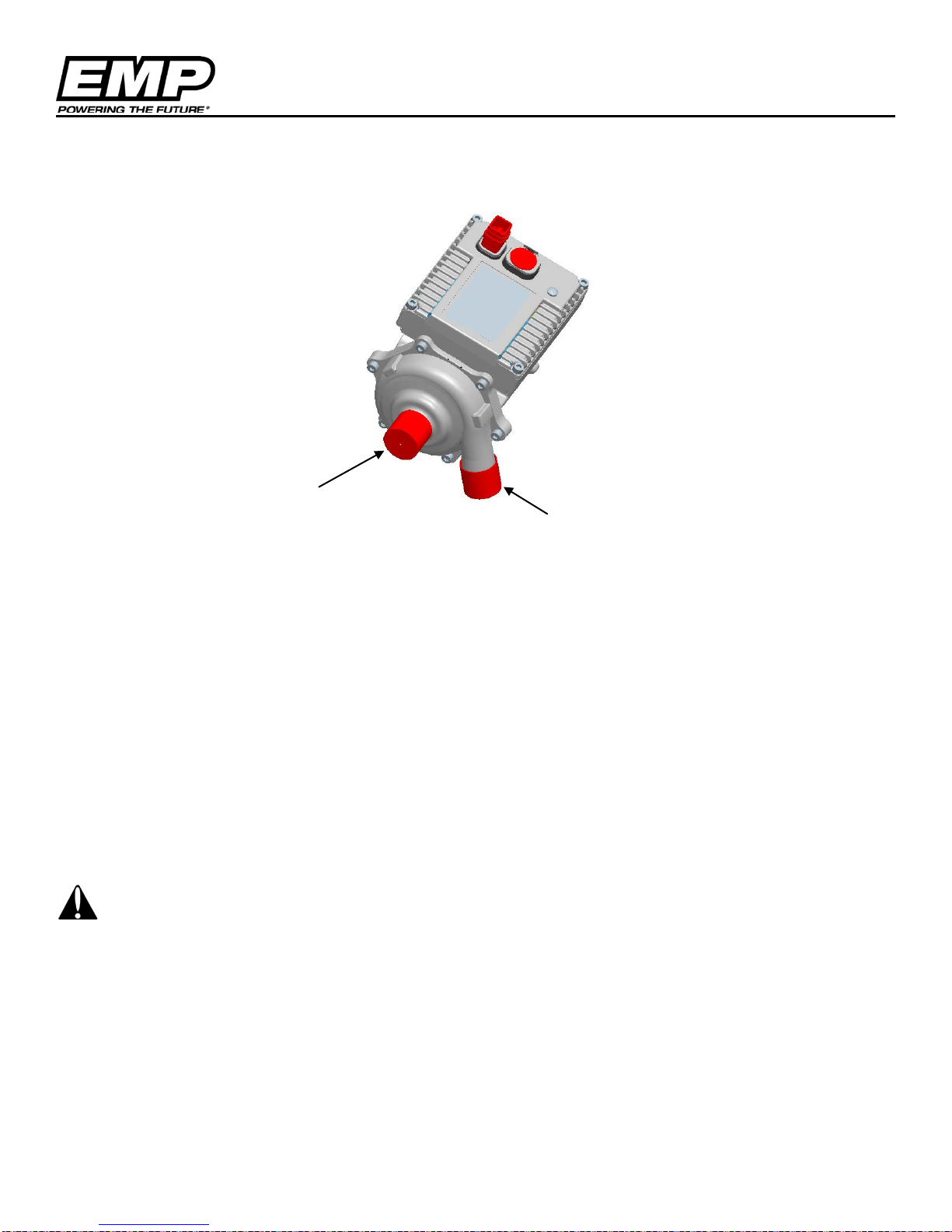
Outlet
Inlet
Plumbing
Recommended Plumbing
Pump Inlet must be plumbed using 25mm (1.0 inch) diameter hose and/or thin walled tubing from the fluid
supply to the pump inlet.
A restriction in the inlet plumbing is allowed as long as the flow diameter is not less than 17mm (0.75 inch) and
does not exceed 25mm (1.0 inch) in lengt h.
Deviations from the Recommended Plumbing must meet the Inlet Requirements and be approved by
EMP Engineering. Please contact EMP customer service for installation review.
Mounting Screws
Mounting screws used should be M8 x 1.25 screws (qty=4). These must have a minimum thread engagement
of 0.50 inch (12.7 mm) and be tightened to a torque of 15 ft-lb (20N-m).
CAUTION: THE MOUNTING HOLES ARE TAPPED TO A DEPTH OF 0.59 INCHES (15MM). BE AWARE OF
THE BRACKET THICKNESS WHEN SELECTING THE FASTENER LENGTH TO ENSURE THAT THE FASTENER
WILL NOT BOTTOM OUT IN THE PUMP HOUSING.
Hose Clamps
When making the inlet and outlet hose connections to the pump it is strongly recommended to use SAE20CT
worm drive type hose clamps. Torque worm drive clamps to 45 in-lbs per SAE J1508. Spring type c lamps are
not recommended.
© 2013 EMP, Inc 13
Page 14
Electrical
12V Pump
Parameter
Min
Nom
Max
Units
Vin – Operating
9.0
13.5
16
V
Operating current
-
- 25
(1)(2)
A
Ignition off current
- - 300
µA
Motor off current
-
80
-
mA
Inrush current
- - 205
(3)
A
Inrush current duratio n
- - 270
µS
24V Pump
Parameter
Min
Nom
Max
Units
Vin – Operating
18
27.0
32
V
Operating current
- - 15
(1)(2)
A
Ignition off current
- - 300
µA
Motor off current
-
60
-
mA
Inrush current
- - 370
(3)
A
Inrush current duratio n
- - 250
µS
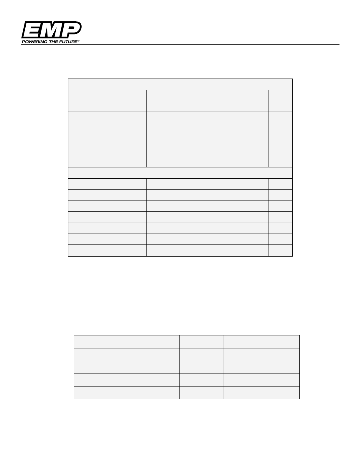
Electrical Specifications and Requireme nts
Vehicle Battery Parameters
(1): Peak current is based on the software current limit. 25 amps is the standard current limit for a 12V pump and 15 amps is the standard
current limit for a 24V pump for serial numbers > 07065826.
(2): The pump shuts down when the i nternal controller temperatures reaches 130˚C at this point the pump will stop running until the internal
controller temperature drops below 125˚C. Once t he safe value is reached, the pump will restart. No ignition cycle is required to restart the
pump.
(3): The inrush current occurs when the controller first receives the required voltage on the ignit ion pin. This current inrush is due to the
charging of the bulk capacitors in the controller. The inrush current numbers are worst case. They were measured with a battery as the source
with a harness that was 3ft in length (very low source impedance). Anything done in the application to increase the source impedance will have
a significant (downward) impact on these numbers. This current is not generated every t im e the motor is started, but only when the igniti on line
is first applied.
Vehicle Ignition Parameters
Parameter Min Nom Max Unit
Vin 9 13.5 or 27 32 V
IGN Current (13.5v)
IGN Current (27.5v)
- 2.5 - mA
- 4 - mA
Vin – Low (sleep) -50 0 1 V
© 2013 EMP, Inc 14
Page 15
Schematics
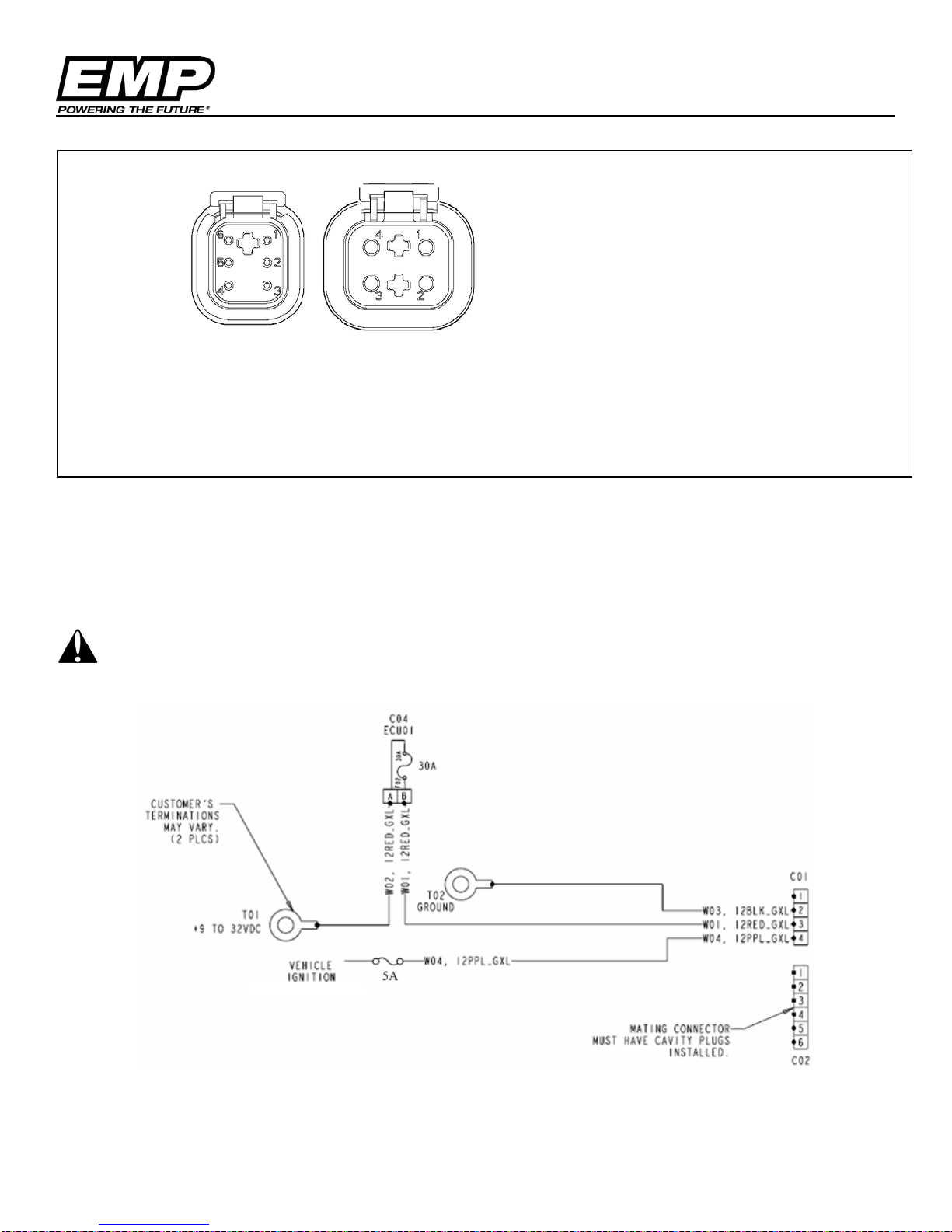
NOTE:
Electrical
1 – CANH
2 – CAN SHIELD
3 – SERIAL GND
4 – SERIAL TX
5 – SERIAL RX
6 – CANL
These represent the controller connectors – not the mating harness
connectors.
1 – TEMP INPUT OR CAN ADDRESS
2 – GND
3 – BATT
4 - IGNITION
NOTE: Addressing and motor status message information can be found in our
J1939 Motor Control Document, 9980010068
Controller Connectors
Mating Connectors
The mating connectors and pins are available from EMP in kit #3170001077 for the 6 pin and #3170001078 for
the 4 pin connector.
IF CAN OR SERIAL TTL CONTROL IS NOT USED THE 6 PIN DTM CONNECTOR MUST BE BLOCKED OFF TO
PREVENT ENTRY OF WATER OR DIRT WHICH WILL RESULT IN DAMAGE TO THE PUMP. A BLOCK OFF PLUG,
EMP P/N 3250001030 CAN BE PURCHASED.
© 2013 EMP, Inc 15
Sample Wiring Schematic
Page 16
Electrical
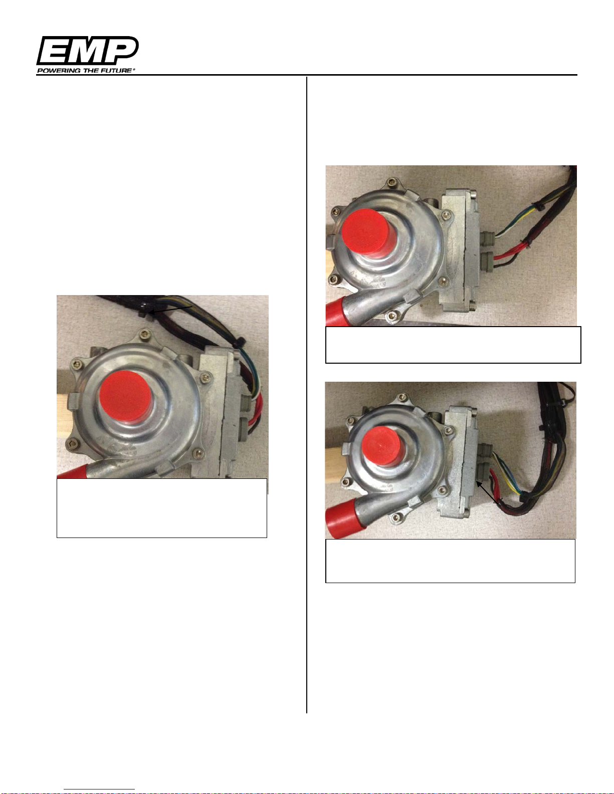
Wires pulling on connectors can
event
Wire routing provides a path for water to flow
Drip loop collects water and sheds it away
Wiring
Wire Sizing
- For complete connector body sealing the
ignition wire should be 16ga minimum and
the power and ground wires should be 12ga
minimum
Recommended Wiring Practices
- Wiring or electrical harness must not rub on
sharp edges.
- The electrical harness should not be
stressed at connections (see Figure below)
-
- Incorporate Drip Loops into wiring designs
(see Figure below). The pump connectors
are environmentally sealed. However, good
wire management can help ensure a good
seal over the life of the product
down into connector
compromise the connector body seal
and possibly create a water intrusion
- The voltage drop between the battery and
the fan should not exceed 5% of the rated
battery voltage. This should be verified at
the pump’s maximum current draw.
Wiring or electrical harness must not rub or
make contact with a hot surface. There
should be 5" minimum clearance from the
exhaust.
- Wiring or electrical harness should be
supported at least every 18" to 20".
- To avoid possible fire or shock, do not pinch
any wiring or electrical harnesses.
-
© 2013 EMP, Inc 16
from connectors
- The use of Dielectric Grease such as Dow
Corning DC-4 is acceptable as long as the
connection is mated directly after grease
application to prevent dirt from being
captured by the grease
Page 17
Orientation
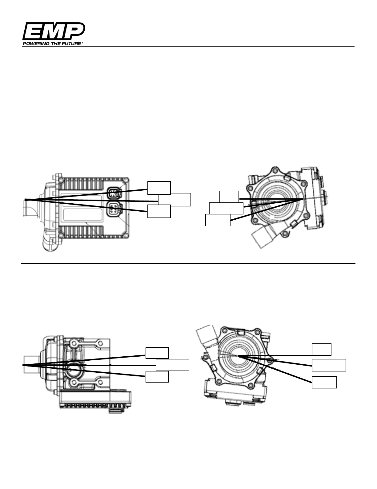
0°
-5°Nom
-15°
0° Nom
10°
-10°
-10°
0°
-5°Nom
-15°
Installation
Orientation Specific
For orientation specific pumps, acceptable pump orientations are tied to the individual pump part numbers.
The part number includes the motor stator for the appropriate voltage, the controller circuit board, and the vent
port configuration.
Vertical Controller Ori e nt a ti on
Part numbers for this orientation include:
1030002275, 1030002278, 1030002280, 1030002283, 1030002285, 1030002287, 1030085013, 1030085016,
1030085018, 1030085019, 1030085021, 1030085023
10°
0° Nom
Horizontal Controll e r Or ientation
Part numbers for this orientation include:
1030002276, 1030002277, 1030002279, 1030002284, 1030002286, 1030002288, 1030085014, 1030085015,
1030085017, 1030085020, 1030085022, 1030085024
© 2013 EMP, Inc 17
Page 18
Orientation
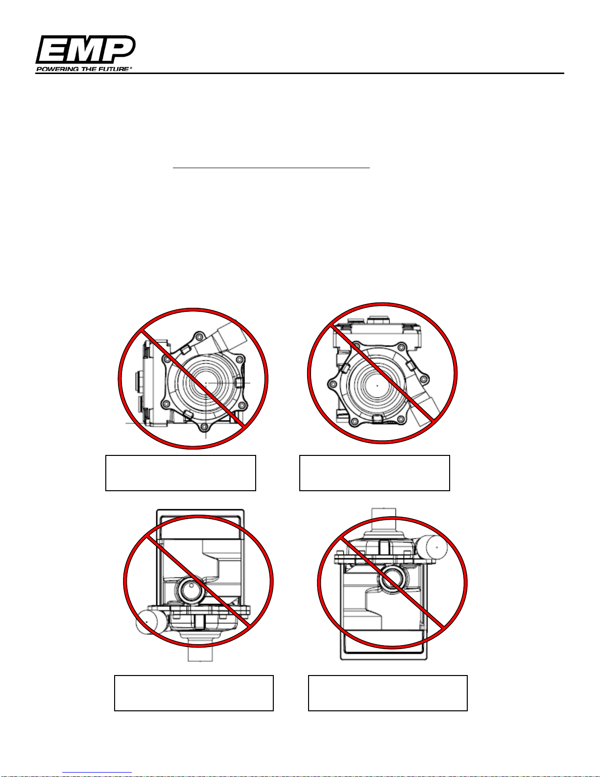
Not Acceptable Orientation
Not Acceptable Orientation
Not Acceptable Orientation
Not Acceptable Orientation
Dual Orientation
Part Numbers Include: 1030002225, 1030002228, 1030002229, 1030002230, 1030002231, 1030002232,
1030002237, 1030002247 thru 1030002251, 1030085001 thru 1030085012
The Dual Orientation pumps cannot be mounted at any arbitrary angle (i.e. 45 deg off axis). Standard Service
pumps can use either the Vertical or Horizontal Orientations listed on the previous page.
Incorrect Pump Orientation and Reasons
The WP29 and WP32 contain a mechanical seal; 0.1cc/hr may weep past the seal as a part of normal
operation. To properly collect the weepage pump orientation is important. Too steep of an angle will
not allow the fluid to collect in the weep pocket and evaporate off and the pump may appear to be
leaking when in fact it is operating as designed. An incorrect mounting angle may also result in too
much fluid being retained in the weep pocket resulting in bearing contamination and reduced service
life.
No Weep Collection
Seal Life
Water in Connectors
Bearing Life
© 2013 EMP, Inc 18
Page 19
Physical Inspection
Physical Inspection
CAUTION: DO NOT RUN THE PUMP WITHOUT FLUID PRESENT. IF RUN DR Y EVEN FOR A SHORT
PERIOD THE SEAL WILL BE DAMAGED.
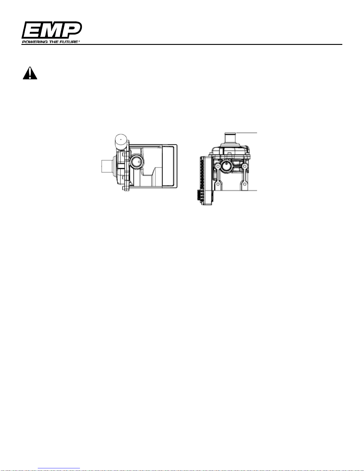
1. Make sure the weep hole ports are not clogged with debris. If weep holes are plugged then
open them up.
Weep Hole Ports
2. While the pump is connected to the bus, remove the 6 pin plug and connect the TTL adapt er
and turn the bus and heating switches "on" (to enable pump).
a. 24V power and IGN must be supplied to pump or it will not connect to the service tool.
b. Use EMPower Connect™ Service Tool to verify that the pump is on and running at
correct speed.
3. Evaluate the pump for abnor mal noi ses dur i n g operati o n. This is a subjective evaluation,
vibration is not grinding; the user is looking for a noticeable bearing noise.
4. Observe the pump and area for leaking coolant. Fluid pouri ng out of the weep hol e w ould
indicate a failed mechanical seal. Dampness around the weep pocket is acceptable.
NOTE:
COOLANT MAY BE SEEN OUTSIDE THE EMP WP29 ELECTRIC WATER PUMP. Mechanical Seal
design requires fluid between the shaft and the seal material. This fluid vaporizes and passes the
seal, venting through the weep collection pocket. As the seal wears in, the amount of venting
decreases but never to zero.
In properly oriented pumps, the vapor will harmlessly evaporate unless the outside surfaces are
cool enough to condense the vapors, which may result in a small volume of coolant visible on the
exterior of the weep holes
There are two weep holes that vent from the same cavity. One will be capped with a solid plug,
the other with a cap with two holes. If the pump seals are leaking excessively, fluid will come
through the holes.
Acceptable Leakage
Depending on pump installation orientation, pumps may show up to 10 cc external leakage during
the first 100 hours. In the preferred orientation, about half this amount may have external leakage.
10 cc coolant will make a small puddle approximately 4 inches across on a flat surface.
9970002273, REV A, 21NOV12 © 2012 EMP Advanced Products 19
Page 20
Troubleshooting
Verify pin location
Check pump inlet for trapped debris
address is being used.
ump bearings are making a grinding noise
• Replace pump
• Replace pump. No action is required by
leakage as described
Troubleshooting
Symptom Check
Pump not running.
Pump is running but not pumping fluid.
No CAN communication and/or pump not
responding to CAN commands
P
when running
• Check electrical connections
• Check ignition wire
• Check if ignition wire is “on”
•
• Check system fluid level
• Check for tubing restrictions (kinks)
• Make sure pump is primed
• Check for collapsed inlet or outlet hose
•
• Check communication harness wiring.
• Verify that CAN messages are being
transmitted in the proper formats (see
online Technical Guide or contact EMP
Technical Support for C AN mess ag e
details).
• Verify that the proper component CAN
Pump is leaking excessively while running
EMPower Connect™ Service Tool
Monitoring operation and manual control of the pump can be accomplished using the service tool
EMPower Connect which is part of the EMP Service Suite available at no cost on our website at:
http://www.emp-corp.com/support/downloads/ . To use EMPower Connect download and install on
your PC. If the pump is being run standalone you will also need an interface cable from the 6 pin
Deutsch connector on the pump and an EMP USB/TTL converter. Both are available as a kit P/N
7500038001. If the pump is on a J1939 CAN bus EMPower Connect™ can be run using a Data Link
Adapter (DLA) to interface to the CAN bus.
A user guide for EMPower Connect™ can be found here:
http://www.emp-corp.com/support/documents/
© 2013 EMP, Inc 20
customers for pumps ex hi bi ti ng acceptable
Page 21
Appendix A, WP29 and WP32 Testing
Pump Inlet Pressure
Required
-15 psi to 30 psi
Pump Outlet Pressure
Recommended
0 psi to 50 psi
Pump Inlet or Outlet
Temperature
Required
0°C to 100°C
EMP Service Tool
Required
Pump Speed Control,
Pump Voltage
Circuit Flow
Optional
Ensure Flow meter does
the system.
Append ix A, WP29 and WP32 Installation Testing
The information provided in this document supplements the Installation Approval document and provides
detailed information for service tool use with the WP29 and WP32. The information within this document may
be helpful in developing unique system calibrations and mapping the operation of the cooling system.
Equipment Required for WP29 and WP32 Data Collection
1. Computer with the EMPower Connect service tool software installed.
2. Computer Interface Hardware with the WP29 and WP32
a. Using DLA: EMP Harness 3180001080 (may need power for DLA)
b. Using an EMP TTL: Service Tool EMP Kit # 7500038001
3. Data Acquisition Equipment Capabilities:
Pump Current
Measurement,
not generate a restriction in
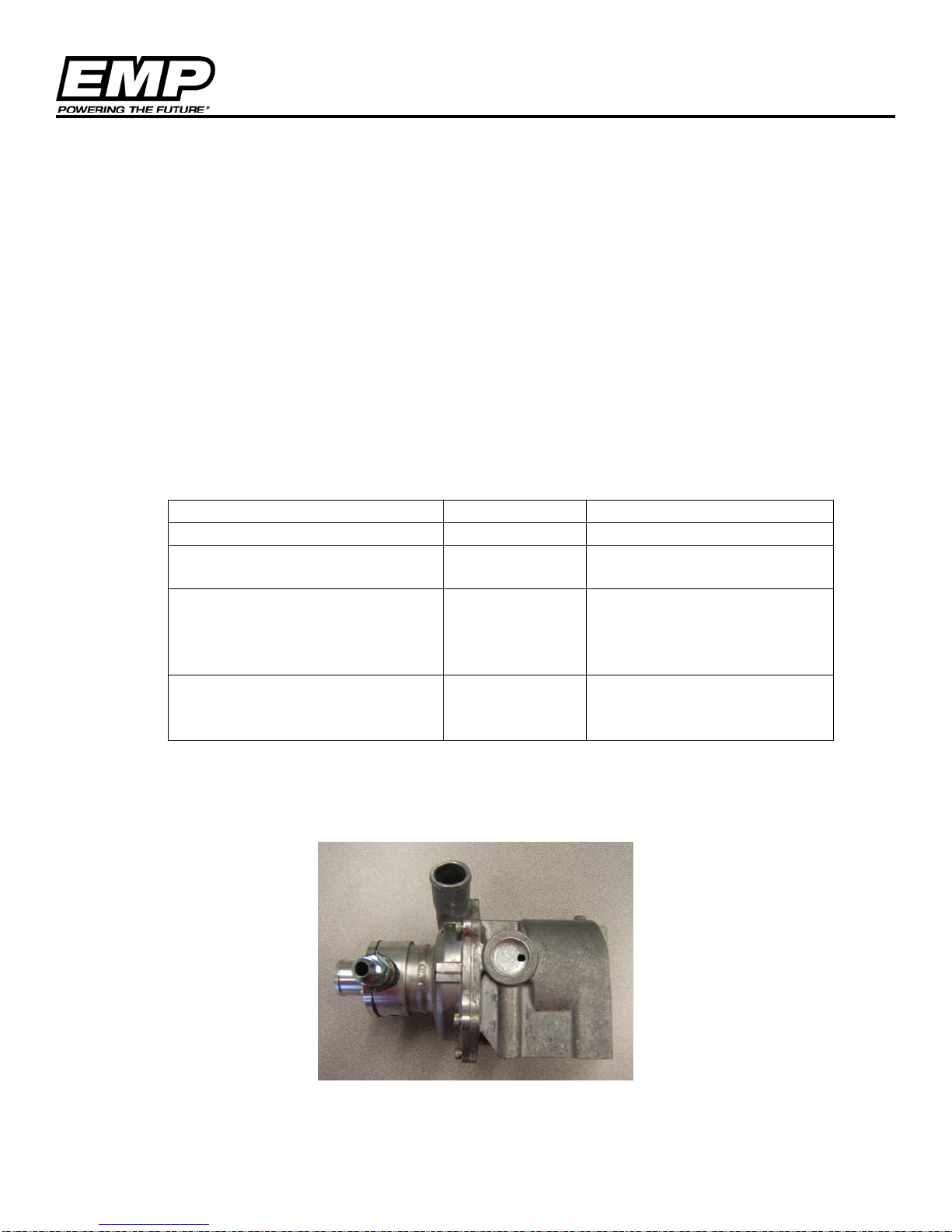
4. For inlet pressure measured within one inch of the pump inlet, a special test pump with an
instrumented inlet is available from EMP for installation approval testing. Contact EMP Engineering
for access to the test pump (shown below).
© 2013 EMP, Inc 21
Page 22
Appendix A, WP29 and WP32 Testing
Inlet Pressure Measurement Test Procedure
1. Install Instrumented WP29 and WP32 into the system.
a. If a non-instrumented WP29 and WP32 is to be used with an external sensor, ensure the
sensor is located within 2 inches of the pump inlet and 4 inches from the last bend in the
supply plumbing.
2. Application Simulation:
a. The pump shall be tested under the worst case conditions for the intended application.
b. If used in a pressurized system, test with the system pressure cap open to atmosphere
c. If used in a system where supplemental flow is provided, test at the minimum anticipated
supplemental system operation.
d. If possible, test at the highest anticipated fluid temperature.
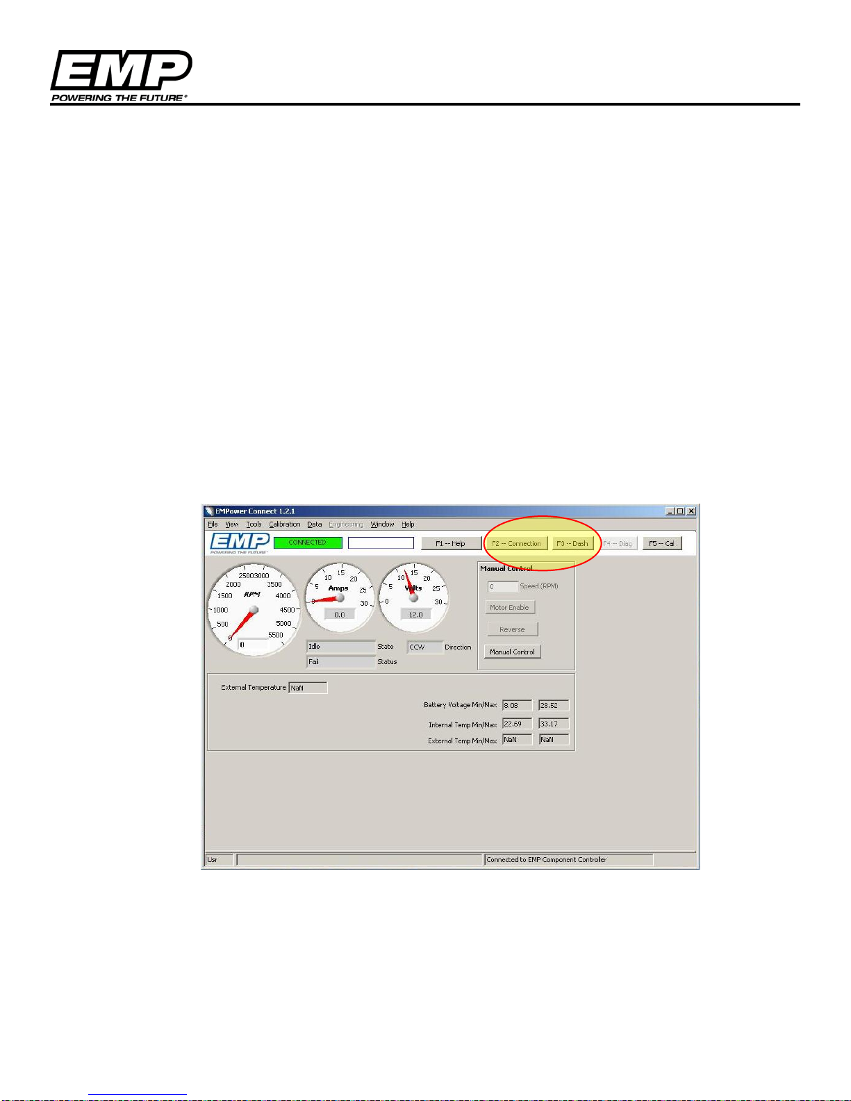
3. Operate the pump using the service tool manual control, press F2 to connect
4. Once connected, go to the “Dash” by selecting F3 or the F3-Dash button on the service tool banner.
This will provide the following screen for the component control.
© 2013 EMP, Inc 22
Page 23
Appendix A, WP29 and WP32 Testing
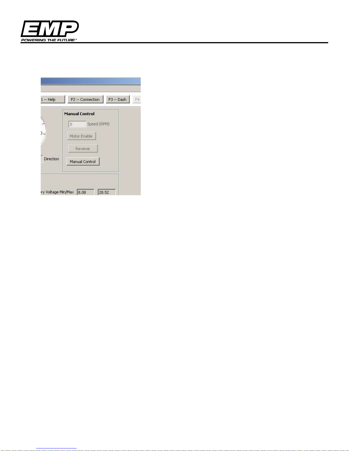
5. To manually control the WP29 and WP32 pump speed:
Step 1 Select “Manual Control” button
Step 2 Select “Motor Enable” button
Step 3 Enter pump test point speed
Press the enter button
Step 4 Record Test Data on the Installation Data Sheet
Step 5 Adjust pump speed for the next data point and record test
data. Repeat step5 until matrix is complete.
Step 6 Select “Manual Control” button to return to normal
operation. Motor Enable and Reverse will be grey as shown in
the im age.
6. Record the requested test information in the data sheets below.
© 2013 EMP, Inc 23
Page 24
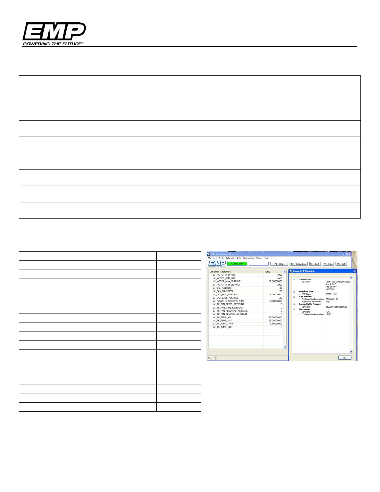
Appendix A, WP29 and WP32 Testing
Customer Calibrations
Value
LV_MOTOR_RPM_MIN
LV_MOTOR_RPM_MAX
LV_MOTOR_MAX_CURRENT
LV_MOTOR_RPM_DEFAULT
LV_CAN_ADDRESS
LV_CAN_FUNCTION
LV_CAN_MSG_TIMEOUT
LV_CAN_BASE ADDRESS
LV_POWER_SHUTDOWN_TIME
LV_TK_FAN_SPEED_SETPOINT
LV_TK_FAN_TIME_REVERSAL
LV_TK_FAN_REVERSAL_INTERVAL
LV_TK_FAN_REVERSE_AT_START
LV_TK_FAN_TEMP_MIN
LV_TK_FAN_TEMP_MAX
LV_TK_FAN_TEMP_HYST
LV_TK_FAN_TEMP_BINS
Test Data Log Sheet
Installation Description
Pump Hardware & Software Numbers (Label)
Fluid Type
Unit or Vehicle Description and #
Coolant Type
Evaluation Date
Evaluation Location
Evaluator Contact Information
NOTE:
Calibration Tab, View Calibrations
Controller Settings from EMPower Connect service tool
© 2013 EMP, Inc 24
Page 25
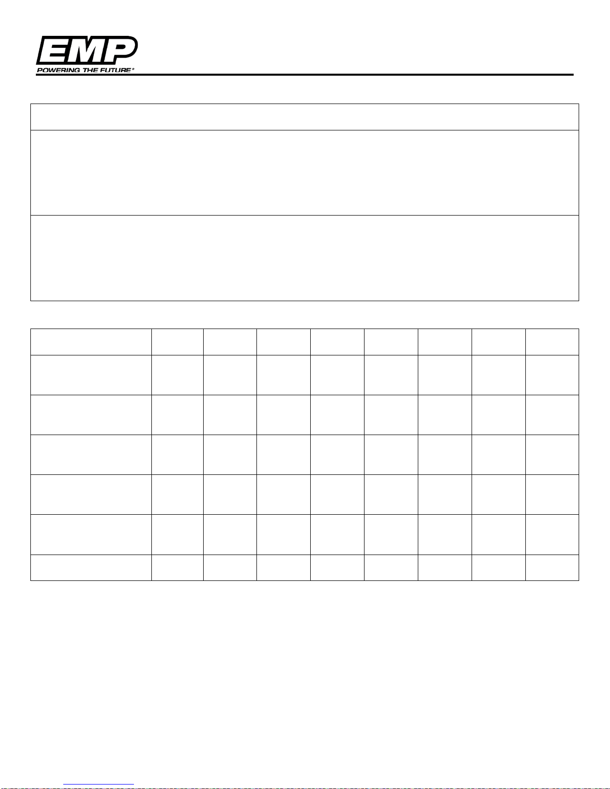
Appendix A, WP29 and WP32 Testing
Installation Description
Test Configuration
Special Conditions:
Test Data Log
Pump Speed (rpm) 0 1000 2000 3000 3500 4000 4300 4600
Pump Current
(Amps)
Pump Voltage
(VDC)
Inlet Pressure
(kPa/psi)
Inlet/Outlet
Temperature (F/C)
Outlet Pressure
(optional)
Flow (optional)
NOTE: If the pump is being used in conjunction with another source of coolant flow (e.g. HVAC Boost Pump) perform
measurements at worst and nominal operating conditions.
NOTE: Complete and submit a log page for each inlet or operational condition with the install ati on regis tra tion
information.
© 2013 EMP, Inc 25
Page 26
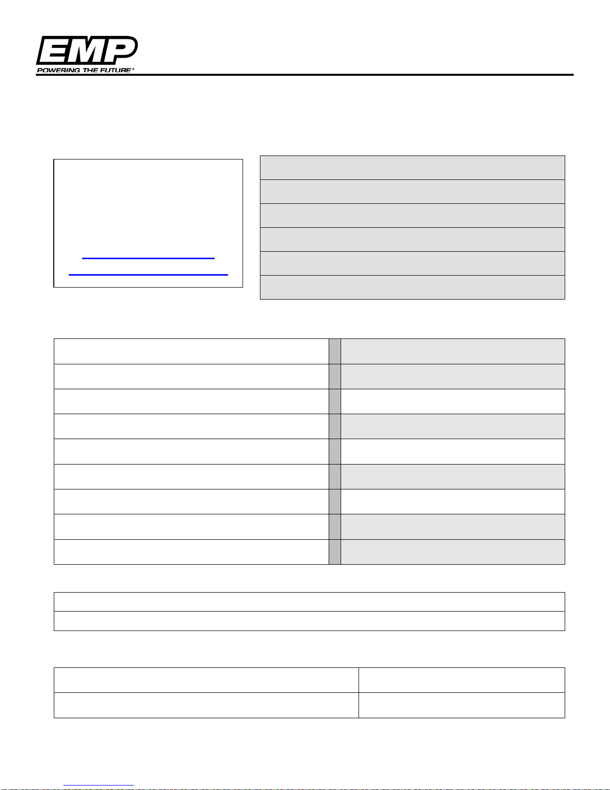
Appendix B, EMPower Connect Service Tool
Installation Approval #
Date Submitted
Reviewer
Approval Date
Approval Signature
Comments
Organization
Street
Pump Hardware Number
City
State/Prov
Pump Hardware Serial Number
Country
Zip Code
Pump Programmed Assembly (PA) Number
Contact
Phone
email
Requestor Signature
Submit Completed Forms to:
Appendix B, WP29 and WP32 Installation Approval Registration and
Check Sheet
To be Completed by EMP
EMP
2701 North 30th Street
Escanaba, Michigan 49829
Phone: 906-789-7497
www.emp-corp.com
To Be Completed By Customer/Reviewer
Product Information
Installation Description, (Vehicle Type, Fluid Type, Mounting Location, Flow Requirements)
I certify that the pump will be used in as described in this installation approval request. I
understand that any deviation from use as de sc r ibed her e may void the warranty on the pump.
Requestor Name Request Date
© 2013 EMP, Inc 26
Page 27
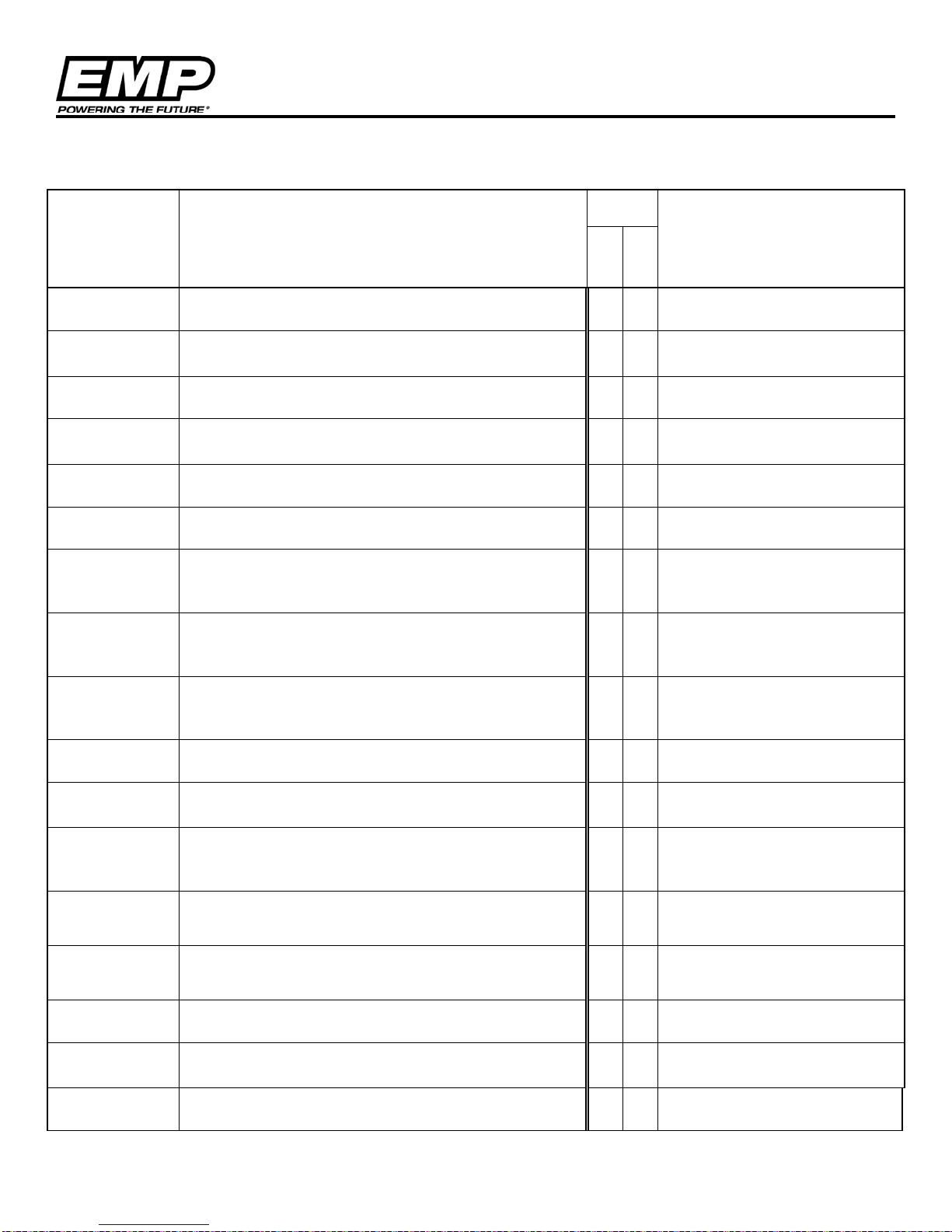
Appendix B, EMPower Connect Service Tool
Input
Met?
Specifications -
Specifications -
Is the maximum system fluid temperature (at the pump
Specifications -
Is the maximum ambient temperature less than or
Specifications -
equal to -40°C?
Specifications -
Is the application vibration enveloped by the EMPTS009
Specifications -
the pump mounted)?
Specifications -
the range of operating speeds?
Specifications -
Is the pump located where there is a minimum 13mm
Specifications -
Is the pump located away from external heat sources
and direct road spray?
Specifications -
Specifications -
Specifications -
Specifications Specifications -
Specifications -
Are the power and ground wires a minimum of 12 AWG
wire?
Product Installation Questionnaire
Reference
Section
Performance
Limitations
Limitations
Limitations
Specifications -
Limitations
Limitations
Limitations
Limitations
Input Requirement
Do the flow and pressure curves match the system
requirements?
inlet) less than or equal to 95°C?
equal to 95°C?
Is the minimum system fluid temperature (at the pump
inlet) greater than or equal to -40°C?
Is the minimum ambient temperature greater than or
profile?
Is the pump's mounting bracket .187" thick or greater?
Does the bracket natural frequency exceed 150 Hz (with
Are any bracket resonances or other audible
abnormalities observed when the pump is run through
No
Yes
Reference Document(s)
and/or
Comments
Limitations
Limitations
Limitations
Limitations
Approved Fluids
Approved Fluids
Electrical
Specifications -
Electrical
Electrical
(1/2 inch) clearance to ensure no rubbing or
interference?
If pump is exposed to external heat and road spray, is
proper shielding in place to protect the pump?
If the pump is exposed to road spray, is the correct
pump orientation (horizontal/vertical) and part number
being used (severe service)?
Is the system fluid on the approved fluids list? Provide
fluid information and spec sheet.
Is the proper shaft material selected for the fluid used
in the application (stainless steel vs carbon steel)
Does the application meet the voltage and current
requirements
Is there a fluid level warning and/or switch to prevent
dry operation of the pump? List the type of system used
© 2013 EMP, Inc 27
Page 28
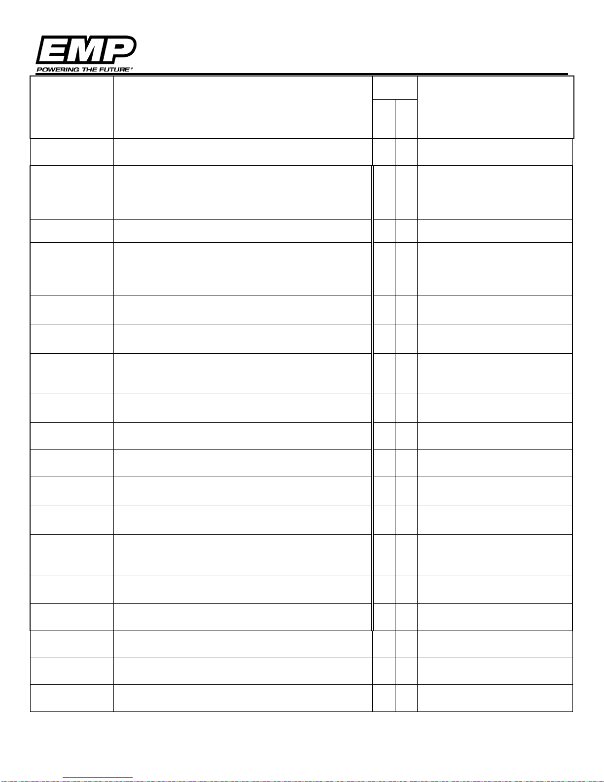
Appendix B, EMPower Connect Service Tool
Input
Met?
Specifications -
Specifications -
Is the ignition (key switch power) fused from the source
ignition source.
Specifications Electrical
Specifications -
If the pump is CAN Controlled, is the CAN harness
Specifications -
address, CAN timeout, baud rate, etc)?
Specifications -
Specifications -
Specifications -
Are electrical cables supported to prevent wear and
abrasion to the cables?
Installation -
Installation -
Installation -
Is there a feature on the pump mounting structure to
Installation -
Are the hoses/tubes supported to reduce the risk of
rubbing?
Installation -
Installation -
Is the WP29 and WP32 inlet plumbing “downhill” from
Reference
Section
Electrical
Electrical
Specifications Electrical
Specifications Electrical
Electrical
Electrical
Input Requirement
Is the positive power wire fused at 30 amps within 6
No
Yes
inches of the voltage source?
or was an additional 5 amp fuse added to the ignition
wire within 6 inches of the ignition source? Identify
Is the Ignition wire a minimum of 16 AWG?
Is the power connected directly to the battery and the
wake/sleep of the pump controlled by the enable
signal? This is required for proper history and fault data
storage.
If the pump is not CAN controlled, is the 6 pin connector
capped and contain all 6 cavity plugs?
potted and are provisions made to seal the shield wire?
If the pump is CAN Controlled, is the pump PA #
properly specified for J1939 communication (J1939
Reference Document(s)
and/or
Comments
Electrical
Electrical
Electrical
Orientation
Orientation
Orientation
Installation Plumbing
Plumbing
Plumbing
Installation -
Plumbing
Power and Plug installed and locked in position, no
stress on the wires at connectors?
Are electrical cables shielded if within 6 inches of an
external heat source?
Is the pump left to right angular orientation 5° to 15°
downward to allow proper weep hole drainage?
Is the pump front to back angular orientation ±10° to
allow proper weep hole drainage?
collect the small amount of weep that may escape the
pump?
Are the inlet and outlet hoses aligned and supported to
reduce loading on the pump and bracket?
Is the WP29 and WP32 inlet plumbing one inch internal
diameter from the coolant source?
Are there 2-3 diameters of straight plumbing directly
before the inlet of the WP29 and WP32?
Plumbing
© 2013 EMP, Inc 28
the coolant source?
Page 29
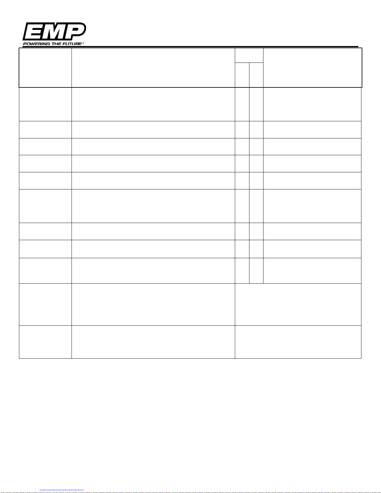
Appendix B, EMPower Connect Service Tool
Input
Met?
Installation -
Installation -
Is the WP29 and WP32 more than 6 inches below the
low fluid level?
Installation -
Installation -
Installation -
Are proper fasteners M8x1.25 used with lock washers
and flat washers?
Installation -
Installation -
Installation -
Have the environmental limitations and the installation
Please describe the systems reaction to a WP29 and
Reference
Section
Plumbing
Plumbing
Plumbing
Plumbing
Mounting
Mounting
Mounting
Installation -
Fault Codes
Input Requirement
Are there any elevated areas in the inlet supply?
NOTE: Areas where air can be trapped and prevent
coolant flow to the pump. The WP29 and WP32 is not a
self-priming pump.
Is the inlet pressure greater than -5psig at maximum
operating speed?
Are there any filters or soft plumbing that could
increase inlet restriction over time?
Do the fasteners have 12.7±1 mm (0.5±0.05 inch)
engagement into the pump?
NOTE: Mounting holes are threaded to 15mm (0.59
inch) depth.
Are the fasteners torqued to the 20±2 Nm (15±1.5 ftlbs) specification?
Are any J1939 feedback parameters other than motor
speed being used for system diagnostics?
No
Yes
Reference Document(s)
and/or
Comments
Requirements
requirements outlined in 9970002273 been reviewed
and agreed to?
WP32 fault.
(e.g. immediate stop, reduced performance, limited
time to operate, system fault code etc..)
If CAN controlled list the CAN messages used for
diagnostics
© 2013 EMP, Inc 29
Page 30

Engineered Machined Products Inc.
2701 North 30th Street
Escanaba, Michigan 49829
Phone: 906-789-7497
www.emp-corp.com
© 2013 EMP, Inc 30
 Loading...