

Emotron M20 Instruction Manual
Emotron M20
Shaft power monitor
Instruction manual
English


CG Drives & Automation 01-5958-01r0 1
Contents
1 Inside the Box............................................................................. 3
2 Safety .......................................................................................... 4
3 Description.................................................................................. 5
4 Getting Started ........................................................................... 7
4.1 Please note ................................................................................................. 7
4.2 Connection and set-up before first start ................................................... 7
4.3 First start ..................................................................................................... 8
4.4 Manual setting of alarm levels, alternative A ........................................... 9
4.5 Manual setting of alarm levels, alternative B ........................................ 10
4.6 Manual setting of alarm levels, alternative C ........................................ 10
5 Wiring ........................................................................................ 11
5.1 Alternative example for single-phase connection ................................. 13
5.2 Example - digital input ............................................................................. 14
6 Selection of Current Transformer ........................................... 14
6.1 Motors less than 100 A........................................................................... 14
6.2 Motors greater than 100 A ..................................................................... 17
7 Operation .................................................................................. 19
7.1 Overview ................................................................................................... 19
7.2 Window menu .......................................................................................... 20
7.3 How to change a value ............................................................................ 21
8 Programming ............................................................................ 22
8.1 Set measurement unit, kW or HP ........................................................... 22
8.2 Setting rated motor power and current (window 41 and 42)............... 24
8.3 Setting number of phases (window 43) ................................................. 25
8.4 Monitor function (window 05)................................................................. 25
8.5 Setting the Start Delay (window 31)....................................................... 27

2 CG Drives & Automation 01-5958-01r0
8.6 Setting alarm levels with Auto set........................................................... 28
8.7 Setting the Response Delay (windows 32 and 34)................................ 29
9 Advanced Features .................................................................. 31
9.1 Setting alarm levels manually (windows 11-14).................................... 31
10 Troubleshooting ....................................................................... 41
11 Technical Data ......................................................................... 43
12 Parameter List.......................................................................... 48
13 Service ...................................................................................... 51
CG Drives & Automation 01-5958-01r0
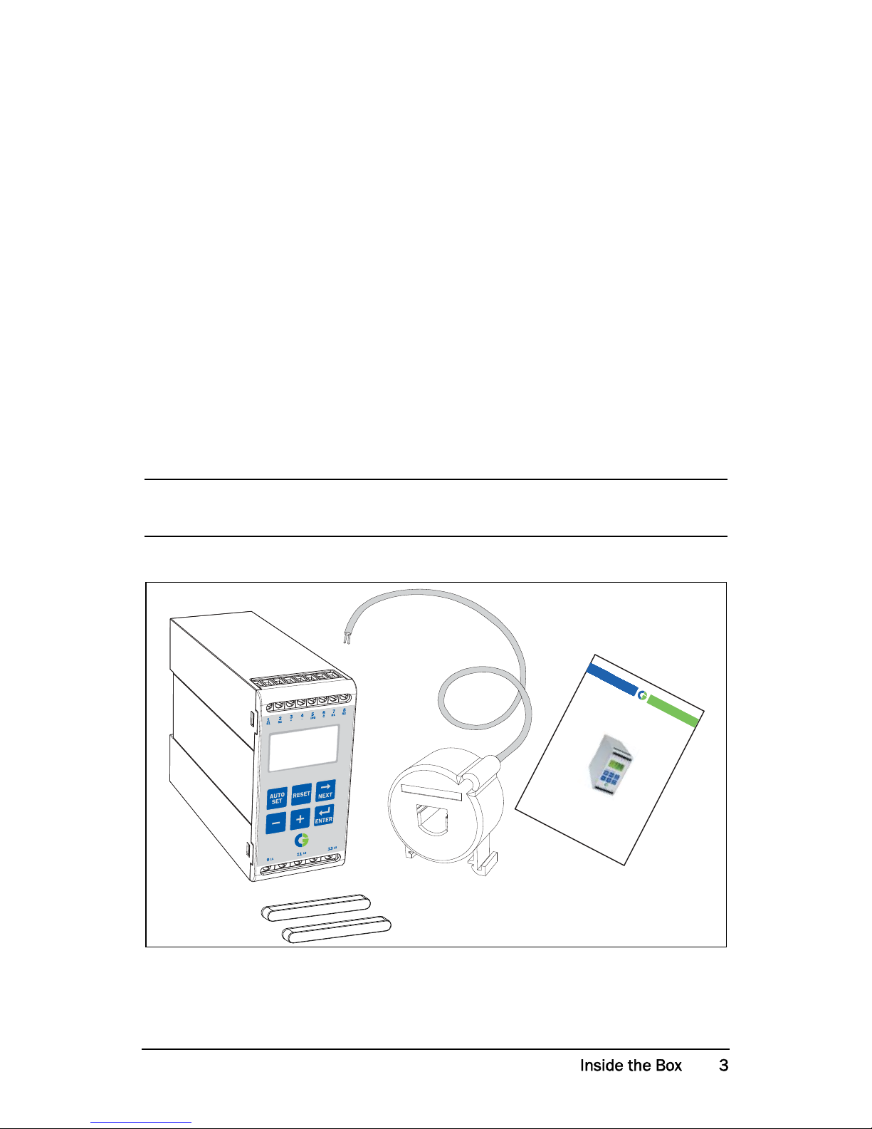
1 Inside the Box
Please check the delivery. Despite the fact that all products from CG Drives &
Automation are carefully inspected and packed, transport damage may occur:
• Your shipment should contain the Emotron M20 shaft power monitor,
a current transformer, 2x terminal covers (option*) and this instruction
manual.
• Check carefully that the equipment ordered complies with the motor’s input
voltage and that the current transformer rating is as stated on the delivery
packaging.
• Check that the contents have not been damaged during shipping.
• If something is missing, or has been damaged, contact the supplier as well as
the forwarding agent within 48 hours of receipt.
NOTE: If in doubt contact your supplier before installing or commissioning
the product.
*)
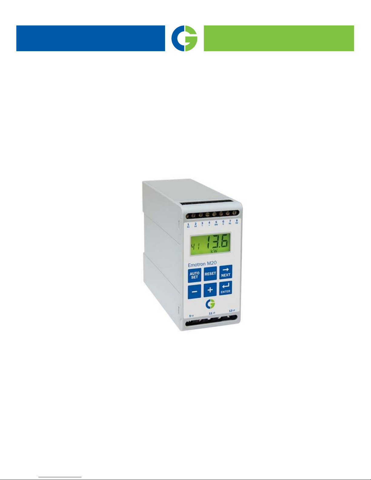
Emotron M20
Shaft power monitor
Instruction manual
English

CG Drives & Automation 01-5958-01r0
2Safety
• Study this manual thoroughly before installing and using the monitor.
• The monitor must be installed by qualified personnel.
• Always disconnect supply circuits prior to installing.
• The installation must comply with standard and local regulations.
• Pay special attention to the information in this chapter and the parts marked
CAUTION in the Operation and Programming chapters.
• Check that the monitor and the equipment are correctly connected before it
is taken into use.
• Should questions or uncertainties arise, please contact your local sales outlet
or see chapter 13, Service.
• Faults that arise due to faulty installation or operation are not covered by the
warranty.
NOTE: Removing or tampering with the seal on the housing will invalidate
the warranty.

CG Drives & Automation 01-5958-01r0
3 Description
This instruction manual describes the installation and commissioning of the
Emotron M20 shaft power monitor. The Emotron M20 supervises induction
motor driven equipment and provides warnings when abnormal conditions are
detected. It protects for example, pumps and other equipment. The M20’s
ability to provide reliable monitoring and protection ensures that production
equipment is optimized and expensive breakdowns and interruptions are
minimized.
The Emotron M20 uses the motor as its own sensor and no external sensors or
extra cabling are required. Due to the special method of subtracting motor
power losses, the monitor is able to accurately measure the shaft power supplied
by the motor to the application. This advanced technique allows the M20 to
monitor only the “application” load rather than the “total” motor load, which
includes the varying motor losses.
The shaft power is calculated by measuring motor input power, and subtracting
the motor power loss calculated using a unique principle. The shaft power
output is indicated on the monitor display in kW or HP, or as a percentage of
rated power. Calculating shaft power gives more reliable supervision than nonlinear techniques, such as current and phase angle measurements. Current
measurement is only sufficient at high motor loads and phase angle only at low
loads. Input power is sometimes called true or real power. Input power is linear,
but ignores motor power loss.
The M20’s analogue output and two relay outputs allow the combination of
direct and indirect control. The unit offers high accuracy in the event of very
small load variations. The analogue output signal can be used to scale the
machine load to represent the actual working range.
The monitor is very easy to install and set up and should be mounted on a
standard DIN rail. It is also very easy to use. The “Auto set” function makes it
possible to adjust the monitor automatically by pressing just one key.
The M20 provides complete flexibility in terms of the type of protection
required for your application. You may select either overload and underload
protection or simply overload with pre-alarm or underload with pre-alarm.
Independent response delays can be selected for both overload and underload
protection. Additional flexibility is provided in the form of programmable
output relays, number of start attempts, number of reversing attempts etc.

CG Drives & Automation 01-5958-01r0
The Emotron M20 shaft power monitor offers advanced multi-function
monitoring and a display for load indication and parameter setting. It is ideal
for
protecting many different applications including pumps in general, centrifugal
pumps, magnetic pumps, screw and impeller pumps, mixers, scrapers, crushers,
conveyor systems, etc.
For further information, please see www.emotron.com.

CG Drives & Automation 01-5958-01r0
4
4.1 Please note
1. Pay special attention to the safety section in this manual and parts marked
CAUTION.
2. Check that motor/supply voltage corresponds to values on the monitor
product label at the side of the unit.
3. Make a note of the motor’s rated power and full load amps from its
nameplate. Confirm that the current transformer supplied is of the correct
size according to tables 1 and 2 in chapter 6 of this manual.
4.2 Connection and set-up before first start
1. Connect the Emotron M20 according to chapter 5 and Fig. 1.
2. Make sure all safety measures have been taken and switch on the supply
voltage.
3. Use the key to scroll through the menu. Press and hold the key and
press the key to scroll back.
4. Set rated motor power and current in windows 41 and 42. Additional
settings to be programmed are discussed in chapter 8.
5. Set monitor function in window 05, overload and underload or only
underload or only overload. See chapter 12, Parameter list, for range and
default values.
6. Set start delay and response delay in window 31 and 32/34.
7. Compare all set values with the parameter list in chapter 12 to confirm that
all relevant values are set. Advanced features will be found in chapter 9.
ENTER

CG Drives & Automation 01-5958-01r0
4.3 First start
1. Start the motor/machine and let it run at normal load, until the Start Delay
has expired.
2. Press for 3 seconds.
Hint!
Short-circuit the output relays during the set-up; this prevents the equipment
from stopping unintentionally.
More Hints!
The monitor can be set in three different ways:
1. Automatically by pressing the Auto set key as described above. The Auto set
function performs a measurement (momentarily) of the actual load and sets
relevant alarm levels for this actual load plus/minus the “margins” (Default;
Max +16% and Min -16%).
2. If Auto set is used as above, the margins can be re-adjusted manually
(windows 21-24). When the margin values are changed a new Auto set must
always be performed to activate the changes and the new margins. More
information is provided in chapter 9, Advanced Features.
3. Manual setting of alarm levels (windows 11-14). The alarm levels can be set
manually, without using the Auto set. See sections Manual setting of alarm
levels, alternative A, B and C.
CAUTION!
Make sure that all safety measures have been taken before switching on
the supply voltage and starting the motor/machine in order to avoid
personal injury.
NOTE: If any window parameter is manually adjusted, the display will flash
the new value to indicate that a change has been made. The Enter key must
be pressed for the M20 to accept this new value.
SET
AUTO
SET
AUTO

CG Drives & Automation 01-5958-01r0
4.4 Manual setting of alarm levels,
alternative A
Running and setting at normal load
• Start the motor/machine or pump and let it run at normal load, until the
Start Delay (window 31) has expired.
• Read off the load on the monitor display, e.g. 65%, window 01
(or kW/HP).
• Set the max. main alarm level to something between e.g. 70-85% in window
11. This must be set to the actual application requirements, maximum load
for machine/process.
• Set the min. main alarm level to something between e.g. 60-45% in window
14. This must also be set to the actual application requirements.
See also Fig. 7 in section 8.4, Over- and underload monitor.

CG Drives & Automation 01-5958-01r0
4.5 Manual setting of alarm levels,
alternative B
Running and setting at maximum load as well as at
minimum load
• Start the motor/machine or pump and let it run at maximum load, until the
Start Delay has expired. E.g. fill the conveyor with maximum allowed goods.
• Read off the load on the monitor display, e.g. 85% (window 01).
• Set the max. main alarm level to something between e.g. 90-95% in window
11. This must be set to the actual application requirements, maximum load
for both machine and processes.
• Then run the motor/machine and let it run at minimum load, e.g. idling,
until the Start Delay has expired.
• Read off the load on the monitor display, e.g. 30%.
• Set the min. main alarm level to something between e.g 25-20% in window
14. This must also be set to the actual application requirements.
See also Fig. 7 in section 8.4, Over- and underload monitor.
4.6 Manual setting of alarm levels,
alternative C
It is also possible to approximately calculate or estimate the alarm levels. If e.g.
the motor used is 22 kW, 22 must be set in window 41. This means that each
percentage point corresponds to 220 W (22 kW/100 = 220 W), and the alarm
limits in window 11- 14 can be set in steps of 220 W. If the max. alarm level is
set to 80% in this example, the monitor will emit an alarm and stop the
machine at approx. max. 17.6 kW shaft output power.
See also Setting alarm levels manually in chapter 9, Advanced Features.
If the pre-alarm is not used, the values for Min. pre-alarm and Max.
pre-alarm can be set to 0 (window 13) and 125% (window 12) respectively.
This will eliminate pre-alarm warning indications in the monitor display
when not in use.

CG Drives & Automation 01-5958-01r0
5 Wiring
The following wiring diagram provides an example of how the M20 can be
connected to control the start/stop circuit of a three-phase motor, Fig. 1.
Connections to a single-phase motor are described later in this manual (Fig. 2)
as are the programming changes necessary for such applications. The default
setting for the M20 is 3-phase.
1. The current transformer CTMxxx must be placed in the same phase that is
connected to terminal 9, phase L1, see Fig. 1. Failure to follow this
requirement will result in the monitor failing to function.
2. For single-phase connection see fig 2.
When using DC voltage, terminal 6 should be connected to negative polarity
(ground) and terminal 5 to positive polarity (max. 48 VDC). See also
Alternative auxiliary circuit (Fig. 16) in chapter 9.
Note: The current transformer (CTMxxx) must be placed in the same phase
that is connected to terminal 9, phase L1, see Fig. 1.
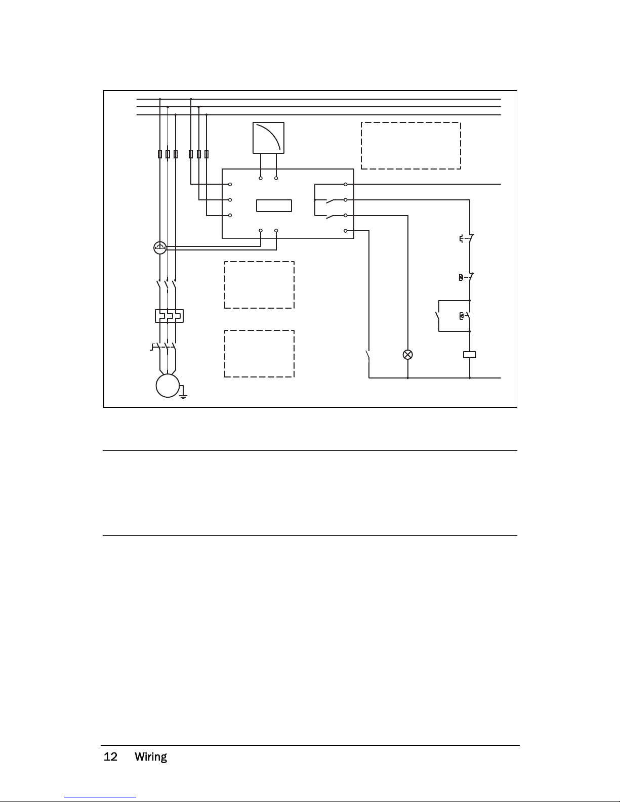
CG Drives & Automation 01-5958-01r0
Fig. 1 Connection example
Please use the enclosed plastic (rubber) insert (if ordered, optional) to cover the
monitor terminals.
NOTE: If the START/STOP is connected as per Fig. 1, it is recommended that
terminals 6 and 7 be bypassed during programming. After the programming
is completed the bypass must be taken out. Make sure that the monitor
voltage range e.g. 3x380-500 VAC matches the connected motor/line
voltage, e.g. 3x 400 V.
M20
A+ A-
R1
R2
C
L1
L3
L2
S2S1
DIG
{
L1
L2
L3
K1
UVW
M
K1
K1
3
4
9
11
13
1
2
6
7
8
5
Stop
Start
N (alt. 48 VDC+)
Max. 240 VAC (alt. 0 VDC-)
NOTE: in power down,
both relays are alwas
N.O.
Please see CTM
information
on Page 11.
NOTE: Monitor
voltage see
Note below.
CG Drives & Automation 01-5958-01r0
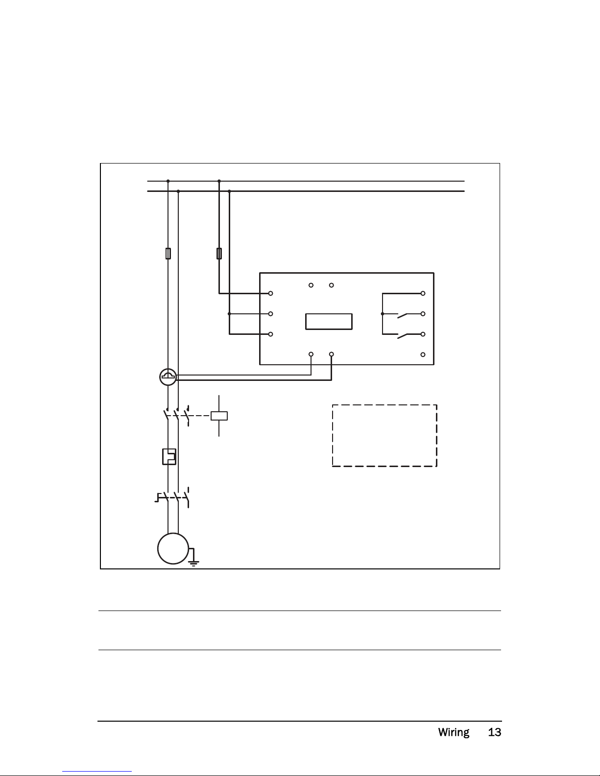
5.1 Alternative example for single-phase
connection
This wiring example shows the connections required for single-phase
applications.
Refer to Fig. 1 for the remaining wiring.
Fig. 2 Single-phase connection example.
NOTE: In Fig. 2 make sure that the monitor voltage range e.g. 1x100-240 VAC
matches the connected motor/“line – neutral” voltage, e.g. 1x 230 V.
N
L1
DIG
S1 S2
L2
L3
L1
C
R2
R1
A-A+
M20
5
8
7
6
2
1
13
11
9
4
3
L
N
M
K1
NOTE: Monitor
voltage, see
note below.
CTMxxx
CG Drives & Automation 01-5958-01r0
5.2 Example - digital input
The digital input uses terminals 5 (DIG) and 6 (C - reference). Either a VAC or
a VDC signal may be used. Connect + to terminal 5 (DIG) and - to terminal 6
for VDC signal. Please note the polarity when DC voltage is used. See also
Fig1
and terminal 6: Max. 240 VAC (or 0 VDC-) and on terminal 5: N
(or 48 VDC+).
See also chapter 9, Advanced Features.
Fig. 3 Wiring example for digital input.
6 Selection of Current Transformer
6.1 Motors less than 100 A
1. Check the rated motor current on the motor plate.
2. Compare this value with the current in Table 1.
3. From Table 1, select the current transformer and the appropriate number of
windings.
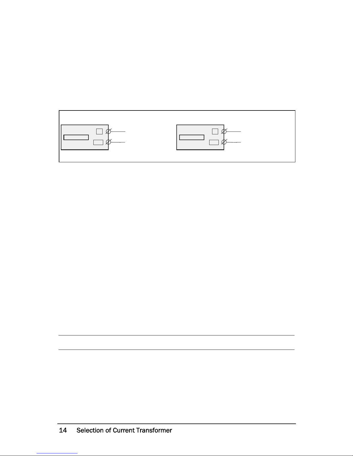
Fig. 5 shows the different types of current transformer (CT) windings. In Fig.
5:1 the motor wire is just drawn through the CT, in the text and tables below
this is described as 1 (one) winding. Fig. 5:2 shows a CT with 2 windings and
Fig. 5:3, 3 windings. In other words the number windings is equal to the
number of times the motor wire “L1” is drawn through the hole of the current
transformer.
NOTE: Maximum length of the CTM cable is 1 m (39 inches).
DIG
C
~
~
DIG
C
+
-
M20 M20
VAC VDC
6
5
6
5
Max 240 VAC
Max 48 VDC
Note polarity!

CG Drives & Automation 01-5958-01r0
Example
• Rated motor current = 12 A.
• Select 10.1-12.5 A from the first column in Table 1.
• This gives:
CTM025 with 2 windings (the motor wire is drawn through the CT’s hole
twice).
In order to ensure an accurate calibration of the M20, it is essential that you use
the correct CTM and apply the exact number of windings in accordance with
the above table.
Table 1 Motors and CT less than 100 A
RATED MOTOR
CURRENT [A]
CURRENT TRANSFORMER TYPE and
NUMBER OF WINDINGS
CTM 010 CTM 025 CTM 050 CTM 100
0.4 – 1.0 10
1.01 – 2.0 5
2.01 – 3.0 3
3.1 – 5.0 2
5.1 – 10.0 1
10.1 – 12.5 2
12.6 –25 1
26 – 50 1
51 – 100 1
NOTE: Normally the appropriate Current Transformer will have been ordered
and shipped with the M20. Check that this is the case; contact the supplier
if in doubt.
 Loading...