

Emotron FDU40-004, FDU40-010, FDU40-006, FDU40-013, FDU40-008 Instruction Manual
...
Emotron FDU 2.0
Variable Speed Drive
Instruction manual
English

Variable speed drive FDU 2.0
INSTRUCTION MANUAL - ENGLISH
Software version 4.0x
Document number: 01-3694-01
Edition: r2
Date of release: 01-04-2007
© Copyright Emotron AB 2005 - 2007
Emotron retains the right to change specifications and illustrations in the
text, without prior notification. The contents of this document may not
be copied without the explicit permission of Emotron AB.


Safety Instructions
Instruction manual
Read the instruction manual first!
Handling the variable speed drive
Installation, commissioning, demounting, taking measurements, etc, of or on the variable speed drive may only be carried out by personnel technically qualified for the task. The
installation must be carried out in accordance with local
standards.
Opening the variable speed drive
WARNING: Always switch off the mains voltage
before opening the variable speed drive and
wait at least 5 minutes to allow the buffer
capacitors to discharge.
Always take adequate precautions before opening the variable speed drive. Although the connections for the control
signals and the switches are isolated from the main voltage,
do not touch the control board when the variable speed
drive is switched on.
Precautions to be taken with a
connected motor
If work must be carried out on a connected motor or on the
driven machine, the mains voltage must always be disconnected from the variable speed drive first. Wait at least 5
minutes before starting work.
Earthing
The variable speed drive must always be earthed via the
mains safety earth connection.
Earth leakage current
This VSD has an earth leakage current which does exceeding
3.5 mA a.c. or 10 mA d.c. Therefore the minimum size of
the protective earth conductor must comply with the local
safety regulations for high leakage current equipment.
Residual current device (RCD)
compatibility
This product cause a d.c. current in the protective conductor. Where a residual current device (RCD) is used for protection in case of direct or indirect contact, only a Type B
RCD is allowed on the supply side of this product. Use
RCD of 300 mA minimum.
EMC Regulations
In order to comply with the EMC Directive, it is absolutely
necessary to follow the installation instructions. All installation descriptions in this manual follow the EMC Directive.
Mains voltage selection
The variable speed drive is suitable for use with the mains
voltage listed below. Adjustment of the mains voltage is not
necessary!
380-415 V
380-480 V
440-525 V
500-690 V
Voltage tests (Megger)
Do not carry out voltage tests (Megger) on the motor, before
all the motor cables have been disconnected from the variable speed drive.
Condensation
If the variable speed drive is moved from a cold (storage)
room to a room where it will be installed, condensation can
occur. This can result in sensitive components becoming
damp. Do not connect the mains voltage until all visible
dampness has evaporated.
Incorrect connection
The variable speed drive is not protected against incorrect
connection of the mains voltage, and in particular against
connection of the mains voltage to the motor outlets U, V
and W. The variable speed drive can be damaged in this way.
Power factor capacitors for improving
ϕ
cos
Remove all capacitors from the motor and the motor outlet.
Precautions during Autoreset
When the automatic reset is active, the motor will restart
automatically provided that the cause of the trip has been
removed. If necessary take the appropriate precautions.
Transport
To avoid damage, keep the variable speed drive in its original
packaging during transport. This packaging is specially
designed to absorb shocks during transport.
Emotron AB 01-3694-01r2 1

IT Mains supply
The variable speed drives can easily be connected to an IT
mains supply, (non-earthed neutral), please contact your
supplier for details.
Heat warning
Be aware of specific parts on the VSD having
high temperature.
DC-link residual voltage
WARNING: After switching off the mains
supply, dangerous voltage can still be present
in the VSD. When opening the VSD for
installing and/or commissioning activities wait
at least 5 minutes. In case of malfunction a qualified
technician should check the DC-link or wait for one hour
before dismantling the VSD for repair.
2 Emotron AB 01-3694-01r2

Contents
1. Introduction..................................................... 5
1.1 Delivery and unpacking ............................................ 5
1.2 Using of the instruction manual............................... 5
1.3 Type number.............................................................. 5
1.4 Standards .................................................................. 6
1.4.1 Product standard for EMC ........................................ 6
1.5 Dismantling and scrapping....................................... 7
1.5.1 Disposal of old electrical and electronic
equipment ................................................................. 7
1.6 Glossary ..................................................................... 8
1.6.1 Abbreviations and symbols....................................... 8
1.6.2 Definitions.................................................................. 8
2. Mounting ......................................................... 9
2.1 Lifting instructions..................................................... 9
2.2 Stand-alone units .................................................... 10
2.2.1 Cooling ..................................................................... 10
2.2.2 Mounting schemes.................................................. 11
2.3 Cabinet mounting.................................................... 13
2.3.1 Cooling ..................................................................... 13
2.3.2 Mounting schemes.................................................. 13
3. Installation ................................................... 17
3.1 Before installation................................................... 17
3.2 Cable connections................................................... 17
3.2.1 Motor cables............................................................ 17
3.2.2 Mains cables ........................................................... 19
3.3 Cable specifications................................................ 19
3.4 Stripping lengths ..................................................... 19
3.4.1 Dimension of cables and fuses.............................. 20
3.4.2 Tightening torque for mains and motor cables..... 20
3.5 Connect motor and mains cables .......................... 20
3.6 Thermal protection on the motor ........................... 21
3.7 Motors in parallel .................................................... 21
4. Control Connections.................................... 23
4.1 Control board........................................................... 23
4.2 Terminal connections ............................................. 24
4.3 Connection example ............................................... 25
4.4 Inputs configuration with the switches.................. 26
4.5 Connecting the Control Signals .............................. 26
4.5.1 Cables ...................................................................... 26
4.5.2 Types of control signals .......................................... 27
4.5.3 Screening................................................................. 27
4.5.4 Single-ended or double-ended connection? ......... 27
4.5.5 Current signals ((0)4-20 mA).................................. 28
4.5.6 Twisted cables......................................................... 28
4.6 Connecting options ................................................. 28
5. Getting Started ............................................ 29
5.1 Connect the mains and motor cables.................... 29
5.1.1 Mains cables ........................................................... 29
5.1.2 Motor cables............................................................ 29
5.2 Connect control cables ........................................... 29
5.3 Using the function keys .......................................... 30
5.4 Remote control........................................................ 30
5.4.1 Switch on the mains ............................................... 30
5.4.2 Set the Motor Data.................................................. 30
5.4.3 Run the VSD ............................................................ 30
5.5 Local control............................................................ 31
5.5.1 Switch on the mains ............................................... 31
5.5.2 Select manual control............................................. 31
5.5.3 Set the Motor Data.................................................. 31
5.5.4 Enter a Reference Value......................................... 31
5.5.5 Run the VSD ............................................................ 31
6. Applications.................................................. 33
6.1 Application overview ............................................... 33
6.1.1 Pumps...................................................................... 33
6.1.2 Fans ......................................................................... 33
6.1.3 Compressors ........................................................... 34
6.1.4 Blowers .................................................................... 34
7. Main Features .............................................. 35
7.1 Parameter sets........................................................ 35
7.1.1 One motor and one parameter set ........................ 36
7.1.2 One motor and two parameter sets....................... 36
7.1.3 Two motors and two parameter sets ..................... 36
7.1.4 Autoreset at trip ...................................................... 36
7.1.5 Reference priority.................................................... 36
7.1.6 Preset references.................................................... 37
7.2 Remote control functions ....................................... 37
7.3 Performing an Identification Run ........................... 39
7.4 Using the Control Panel Memory............................ 40
7.5 Load Monitor and Process Protection [400] ......... 40
7.5.1 Load Monitor [410]................................................. 40
7.6 Pump function ......................................................... 42
7.6.1 Introduction ............................................................. 42
7.6.2 Fixed MASTER ......................................................... 43
7.6.3 Alternating MASTER ................................................ 43
7.6.4 Feedback 'Status' input .......................................... 43
7.6.5 Fail safe operation .................................................. 44
7.6.6 PID control ............................................................... 45
7.6.7 Wiring Alternating Master ....................................... 46
7.6.8 Checklist And Tips ................................................... 47
7.6.9 Functional Examples of Start/Stop Transitions .... 48
8. EMC and Machine Directive........................ 51
8.1 EMC standards........................................................ 51
8.2 Stop categories and emergency stop .................... 51
9. Operation via the Control Panel.................. 53
9.1 General .................................................................... 53
9.2 The control panel .................................................... 53
9.2.1 The display............................................................... 53
9.2.2 Indications on the display....................................... 54
9.2.3 LED indicators ......................................................... 54
9.2.4 Control keys............................................................. 54
Emotron AB 01-3694-01r2 3

9.2.5 The Toggle and Loc/Rem Key ................................ 54
9.2.6 Function keys .......................................................... 55
9.3 The menu structure................................................. 56
9.3.1 The main menu ....................................................... 56
9.4 Programming during operation .............................. 56
9.5 Editing values in a menu ........................................ 56
9.6 Programming example............................................ 57
10. Serial communication ................................. 59
10.1 Parameter sets........................................................ 59
10.2 Motor data ............................................................... 59
10.3 Start and stop commands ...................................... 60
10.4 Reference signal ..................................................... 60
10.5 Description of the EInt formats .............................. 60
11. Functional Description................................ 63
11.1 Resolution of settings ............................................. 63
11.2 Preferred View [100]............................................... 63
11.2.1 1st Line [110].......................................................... 63
11.2.2 2nd Line [120] ........................................................ 63
11.3 Main Setup [200].................................................... 64
11.3.1 Operation [210]....................................................... 64
11.3.2 Remote Signal Level/Edge [21A]........................... 66
11.3.3 Motor Data [220] .................................................... 67
11.3.4 Motor Protection [230] ........................................... 71
11.3.5 Parameter Set Handling [240]............................... 73
11.3.6 Trip Autoreset/Trip Conditions [250]..................... 75
11.3.7 Serial Communication [260].................................. 81
11.4 Process and Application Parameters [300] .......... 83
11.4.1 Set/View Reference Value [310] ........................... 83
11.4.2 Process Settings [320] ........................................... 83
11.4.3 Start/Stop settings [330] ....................................... 87
11.4.4 Mechanical brake control....................................... 90
11.4.5 Speed [340]............................................................. 92
11.4.6 Torques [350].......................................................... 94
11.4.7 Preset References [360] ........................................ 96
11.4.8 PID Process Control [380] ...................................... 97
11.4.9 Pump/Fan Control [390] ...................................... 100
11.5 Load Monitor and Process Protection [400]....... 106
11.5.1 Load Monitor [410]............................................... 106
11.5.2 Process Protection [420]...................................... 111
11.6 I/Os and Virtual Connections [500] ..................... 112
11.6.1 Analogue Inputs [510].......................................... 112
11.6.2 Digital Inputs [520]............................................... 118
11.6.3 Analogue Outputs [530] ....................................... 119
11.6.4 Digital Outputs [540] ............................................ 123
11.6.5 Relays [550] .......................................................... 124
11.6.6 Virtual Connections [560]..................................... 125
11.7 Logical Functions and Timers [600] .................... 126
11.7.1 Comparators [610] ............................................... 126
11.7.2 Logic Output Y [620] ............................................. 130
11.7.3 Logic Output Z [630]............................................. 132
11.7.4 Timer1 [640] ......................................................... 133
11.7.5 Timer2 [650] ......................................................... 135
11.8 View Operation/Status [700] ............................... 136
11.8.1 Operation [710]..................................................... 136
11.8.2 Status [720] .......................................................... 138
11.8.3 Stored values [730] .............................................. 140
11.9 View Trip Log [800] ............................................... 142
11.9.1 Trip Message log [810]......................................... 142
11.9.2 Trip Messages [820] - [890] ................................ 143
11.9.3 Reset Trip Log [8A0] ............................................. 143
11.10 System Data [900]................................................ 143
11.10.1 VSD Data [920] ..................................................... 143
12. Troubleshooting, Diagnoses and
Maintenance .............................................. 145
12.1 Trips, warnings and limits..................................... 145
12.2 Trip conditions, causes and remedial action ...... 146
12.2.1 Technically qualified personnel............................ 146
12.2.2 Opening the variable speed drive ........................ 146
12.2.3 Precautions to take with a connected motor ...... 146
12.2.4 Autoreset Trip ........................................................ 146
12.3 Maintenance ......................................................... 149
13. Options........................................................ 151
13.1 Protection class IP54............................................ 151
13.2 Options for the control panel................................ 152
13.3 EmoSoftCom.......................................................... 152
13.4 Brake chopper....................................................... 152
13.5 I/O Board ............................................................... 153
13.6 Output coils ........................................................... 153
13.7 Serial communication and fieldbus ..................... 153
13.8 Standby supply option .......................................... 153
13.9 Safe Stop option.................................................... 153
13.10 Crane option board ............................................... 155
13.11 Encoder.................................................................. 155
13.12 PTC/PT100 ............................................................ 155
14. Technical Data ........................................... 157
14.1 Electrical specifications related to model........... 157
14.2 General electrical specifications.......................... 159
14.3 Operation at higher temperatures ....................... 160
14.4 Operation at higher switching frequency............. 160
14.5 Dimensions and Weights...................................... 161
14.6 Environmental conditions..................................... 161
14.7 Fuses, cable cross-sections and glands .............. 162
14.8 Control signals....................................................... 163
15. Menu List .................................................... 165
Index 171
4 Emotron AB 01-3694-01r2
1. Introduction
FDU is used most commonly to control and protect pump
and fan applications that put high demands on flow control,
process uptime and low maintenance costs. It can also be
used for e.g. compressors and blowers. Several options are
available, listed in chapter 13. page 151, that enable you to
customize the variable speed drive for your specific needs.
NOTE: Read this instruction manual carefully before
starting installation, connection or working with the
variable speed drive.
The following symbols can appear in this manual. Always
read these first before continuing:
NOTE: Additional information as an aid to avoid
problems.
CAUTION: Failure to follow these instructions
!
can result in malfunction or damage to the
variable speed drive.
WARNING: Failure to follow these instructions
can result in serious injury to the user in addition
to serious damage to the variable speed drive.
HOT SURFACE:
The variable speed drives are delivered with a template for
positioning the fixing holes on a flat surface. Check that all
items are present and that the type number is correct.
1.2 Using of the instruction
manual
Within this instruction manual the abbreviation “VSD” is
used to indicate the complete variable speed drive as a single
unit.
Check that the software version number on the first page of
this manual matches the software version in the variable
speed drive.
With help of the index and the contents it is easy to track
individual functions and to find out how to use and set
them.
The Quick Setup Card can be put in a cabinet door, so that
it is always easy to access in case of an emergency.
1.3 Type number
Fig. 1 gives an example of the type code numbering used on
all variable speed drives
type of the drive can be determined. This identification will
be required for type specific information when mounting
and installing. The code number is located on the product
label, on the front of the unit.
. With this code number the exact
Users
This instruction manual is intended for:
• installation engineers
• maintenance engineers
•operators
• service engineers
Motors
The variable speed drive is suitable for use with standard 3phase asynchronous motors. Under certain conditions it is
possible to use other types of motors. Contact your supplier
for details.
1.1 Delivery and unpacking
Check for any visible signs of damage. Inform your supplier
immediately of any damage found. Do not install the variable speed drive if damage is found.
FDU48-175-54 C E B S T A V C E P N A
12345678910111213141516
Fig. 1 Type number
Position Configuration
1VSD type
2Supply voltage
3 Rated current (A) continuous
4 Protection class
5 Control panel
6 EMC option
FDU
VFX
40=400 V mains
48=400 V mains
50=500 V mains
-003=2.5 A
-
-1500=1500 A
20=IP20
54=IP54
–=Blank CP
C=Standard CP
E=Standard EMC
F=Extended EMC
I=IT-Net
Emotron AB 01-3694-01r2 Introduction 5
Position Configuration
7 Brake chopper option
8 Stand-by power supply option
–=Brake N.C
B=Brake
D=DC interface
-=No SBS
S=SBS included
1.4 Standards
The variable speed drives described in this instruction manual comply with the standards listed in Table 1. For the declarations of conformity and manufacturer’s certificate,
contact your supplier for more information or visit
www.emotron.com.
9 Safe stop option
10 Brand label
11 Coated boards, option
12 Option position 1 N=No option
13 Option position 2
14 Option position 3
15
16 Software type
Option position, communication
–=No safe stop
T=Safe stop incl.
–=No coating
V=Coated boards
C=Crane I/O
E=Encoder
P=PTC/PT100
I=Extended I/O
N=No option
D=DeviceNet
P=Profibus
S=RS232/485
1.4.1Product standard for EMC
Product standard EN(IEC)61800-3, second edition of 2004
defines the :
First Environment (Extended EMC) as environment that
includes domestic premises. It also includes establishments
directly connected without intermediate transformers to a
low voltage power supply network that supplies buildings
used for domestic purposes.
Second Environment (Standard EMC) includes all other
establishments.
Category C2: Power Drive System (PDS) of rated voltage<1.000 V, which is neither a plug in device nor a movable
device and, when used in the first environment, is intended
to be installed and commissioned only by a professional.
Category C3: PDS of rated voltage <1.000 V, intended for
use in the second environment and not intended for use in
the first environment.
Category C4: PDS or rated voltage equal or above 1.000 V,
or rated current equal to or above 400 A, or intended for use
in complex systems in the second environment.
The variable speed drive complies with the product standard
EN(IEC) 61800-3:2004 (Any kind of metal screened cable
may be used). The standard variable speed drive is designed
to meet the requirements according to category C3.
WARNING: In a domestic environment this
product may cause radio interference, in
which case it may be necessary to take
adequate additional measures.
WARNING: The standard VSD, complying with
category C3, is not intended to be used on a
low-voltage public network which supplies
domestic premises; radio interference is
expected if used in such a network. Contact
your supplier if you need additional
measures.
CAUTION: In order to comply fully with the
standards stated in the Manufacturer’s
!
Declaration ANNEX IIB, the installation
instructions detailed in this instruction
manual must be followed to the letter.
6Introduction Emotron AB 01-3694-01r2
Ta b le 1 St an d ar d s
Market Standard Description
Machine Directive 98/37/EEC
European
All
Russian GOST R For all sizes
EMC Directive 2004/108/EEC
Low Voltage Directive 2006/95/EC
WEEE Directive 2002/96/EC
Safety of machinery - Electrical equipment of machines
EN 60204-1
EN(IEC)61800-3:2004
EN50178
(<90 A)
EN(IEC)61800-5-1
≥90 A)
(
IEC 60721-3-3
Part 1: General requirements.
Machine Directive: Manufacturer’s certificate
Adjustable speed electrical power drive systems
Part 3: EMC requirements and specific test methods.
EMC Directive: Declaration of Conformity and
Electronic equipment for use in power installations.
Low Voltage Directive: Declaration of Conformity and
Adjustable speed electrical power drive systems Part 5-1.
Safety requirements - Electrical, thermal and energy.
Low Voltage Directive: Declaration of Conformity and
Classification of environmental conditions. Air quality chemical vapours, unit in
operation. Chemical gases 3C1, Solid particles 3S2.
Optional with coated boards
Unit in operation. Chemical gases Class 3C2, Solid particles 3S2.
acc. to Appendix IIB
CE marking
CE marking
CE marking
1.5 Dismantling and scrapping
The enclosures of the drives are made from recyclable material as aluminium, iron and plastic. Each drive contains a
number of components demanding special treatment, for
example electrolytic capacitors. The circuit boards contain
small amounts of tin and lead. Any local or national regulations in force for the disposal and recycling of these materials
must be complied with.
1.5.1 Disposal of old electrical and
electronic equipment
This information is applicable in the European Union and
other European countries with separate collection systems.
This symbol on the product or on its packaging indicates
that this product shall be treated according to the WEEE
Directive. It must be taken to the applicable collection point
for the recycling of electrical and electronic equipment. By
ensuring this product is disposed of correctly, you will help
prevent potentially negative consequences for the environment and human health, which could otherwise be caused
by inappropriate waste handling of this product. The recycling of materials will help to conserve natural resources. For
more detailed information about recycling this product,
please contact the local distributor of the product or visit our
home page www.emotron.com.
Emotron AB 01-3694-01r2 Introduction 7
1.6 Glossary
1.6.1Abbreviations and symbols
In this manual the following abbreviations are used:
1.6.2 Definitions
In this manual the following definitions for current, torque
and frequency are used:
Table 3 Definitions
Table 2 Abbreviations
Abbreviation/
symbol
DSP Digital signals processor
VSD Variable speed drive
CP
EInt Communication format
UInt Communication format
Int Communication format
Long Communication format
Control panel, the programming and presentation unit on the VSD
The function cannot be changed in run
mode
Description
Name Description Quantity
I
IN
I
NOM
I
MOT
P
NOM
P
MOT
T
NOM
T
MOT
f
OUT
f
MOT
n
MOT
I
CL
Speed Actual motor speed rpm
Torque Actual motor torque Nm
Sync
speed
Nominal input current of VSD A, RMS
Nominal output current of VSD A, RMS
Nominal motor current A, RMS
Nominal power of VSD kW
Motor power kW
Nominal torque of motor Nm
Motor torque Nm
Output frequency of VSD Hz
Nominal frequency of motor Hz
Nominal speed of motor rpm
Maximum output current for 60s A, RMS
Synchronous speed of the motor rpm
8Introduction Emotron AB 01-3694-01r2

2. Mounting
This chapter describes how to mount the VSD.
Before mounting it is recommended that the installation is
planned out first.
• Be sure that the VSD suits the mounting location.
• The mounting site must support the weight of the VSD.
• Will the VSD continuously withstand vibrations and/or
shocks?
• Consider using a vibration damper.
• Check ambient conditions, ratings, required cooling air
flow, compatibility of the motor, etc.
• Know how the VSD will be lifted and transported.
2.1 Lifting instructions
Note: To prevent personal risks and any damage to the
unit during lifting, it is advised that the lifting methods
described below are used.
Recommended for VSD models -090 to -250
Recommended for VSD models -300 to -1500
*
*
*
Load: 56 to 74 kg
Fig. 3 Remove the roof plate.
*
A
DETAIL A
Fig. 4 Remove roofunit
Fig. 2 Lifting VSD model -090 to -250
Emotron AB 01-3694-01r2 Mounting 9
2.2 Stand-alone units
The VSD must be mounted in a vertical position against a
flat surface. Use the template (delivered together with the
VSD) to mark out the position of the fixing holes.
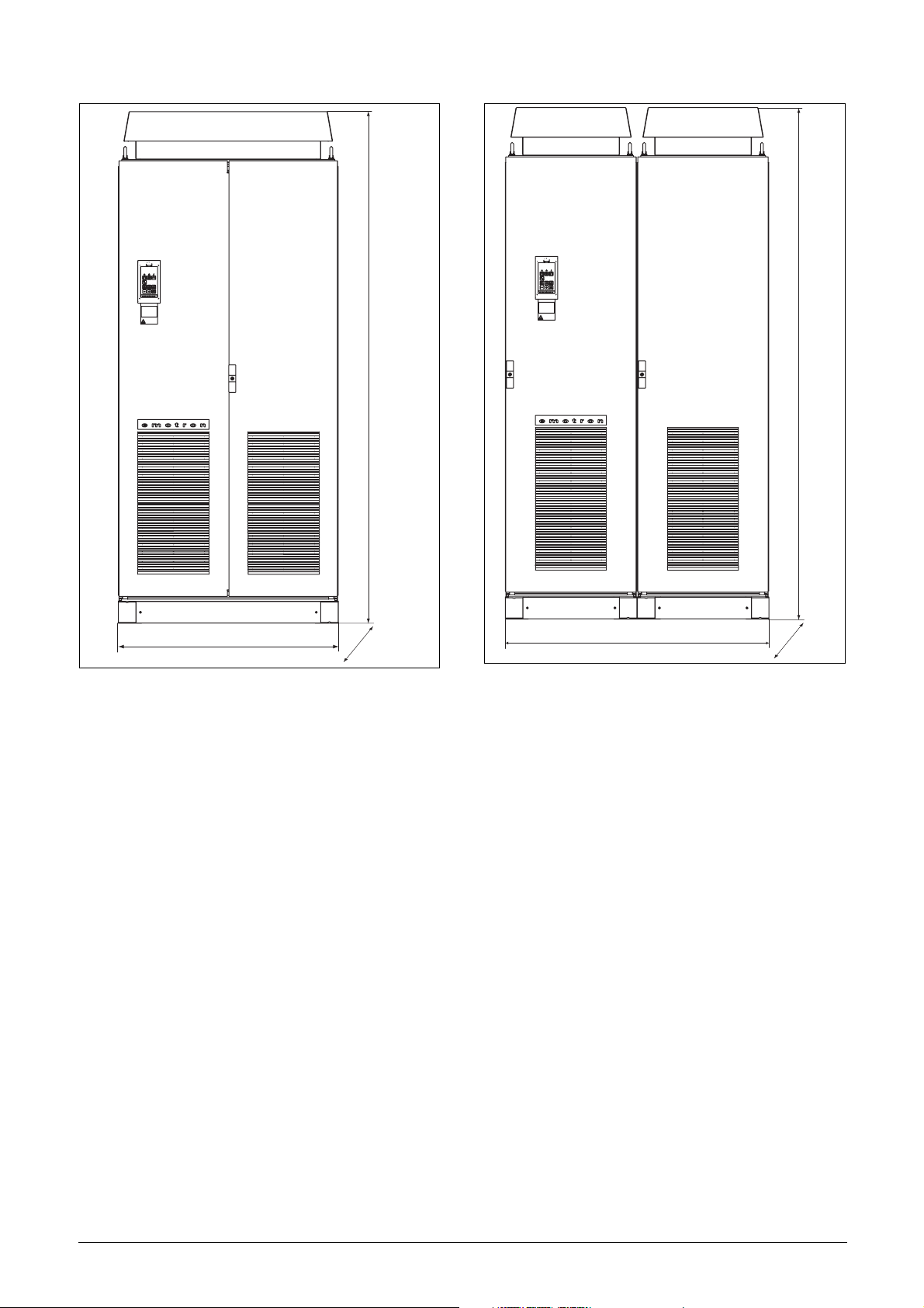
Fig. 6 Variable speed drive mounting models 003 to 250
2.2.1 Cooling
Fig. 6 shows the minimum free space required around the
VSD for the models 003 to 250 in order to guarantee adequate cooling. Because the fans blow the air from the bottom to the top it is advisable not to position an air inlet
immediately above an air outlet.
The following minimum separation between two variable
speed drives, a VSD and a non-dissipating wall must be
maintained:
Fig. 5 Lifting VSD model -300 to -1500
Table 4 Mounting and cooling
003-
013
FDUFDU
(mm)
FDUwall
(mm)
NOTE: When a 300 to 1500 model is placed between two
walls, a minimum distance at each side of 200 mm must
be maintained.
a 200 200 200 200 100
b 200 200 200 200 0
c 30 0 30 0 0
d 30 0 30 0 0
a 100 100 100 100 100
b 100 100 100 100 0
c 30 0 30 0 0
d 30 0 30 0 0
018-
037
046-
073
090-
250
300-
1500
10 Mounting Emotron AB 01-3694-01r2
2.2.2 Mounting schemes
20 180
Ø 13 (2x)
7,5385
23,75 128,5
Ø 13 (2x)
10510
Ø 7 (4x)
220
Fig. 7 VSD models 003 - 013 (X1)
Glands
M20
400
154,5
External
Interface
Ø 7 (4x)
176
Fig. 9 VSD models 018 - 037 (S2)
Glands
M20
530
273
External
Interface
Glands
M25
M32M32
Fig. 8 Cable interface for mains, motor and communication,
VSD models 003 - 013(X1)
Fig. 10 Cable interface for mains, motor and communication,
VSD models 018 - 037 (S2).
Emotron AB 01-3694-01r2 Mounting 11

10570
30 160
Ø 13 (2x)
Membrane cable
gland M60
Ø 7 (4x)
220
590
284,5
275
314
10
925
22,5
Ø16(3)
240
120
Ø9(6x)
952,50
30
922,50
Fig. 13 VSD models 090 - 175 including cable interface for
mains, motor and communication (E)
Fig. 11 VSD models 046 - 073 (X2)
External
Glands
M20
Glands
M40
Interface
Fig. 12 Cable interface for mains, motor and communication,
VSD models 046 - 073 (X2)
12 Mounting Emotron AB 01-3694-01r2
Cable dimensions 27-66 mm
NOTE: For the models 860 to 1500 the mentioned
amount of air flow should be divided equally over the two
cabinets.
2.3.2 Mounting schemes
22.50
10
925
Ø16(3x)
300
Ø9(x6)
150
30
922,50
952,50
344,5
335
314
Fig. 14 VSD models 210 - 250 including cable interface for
mains, motor and communication (F)
2320
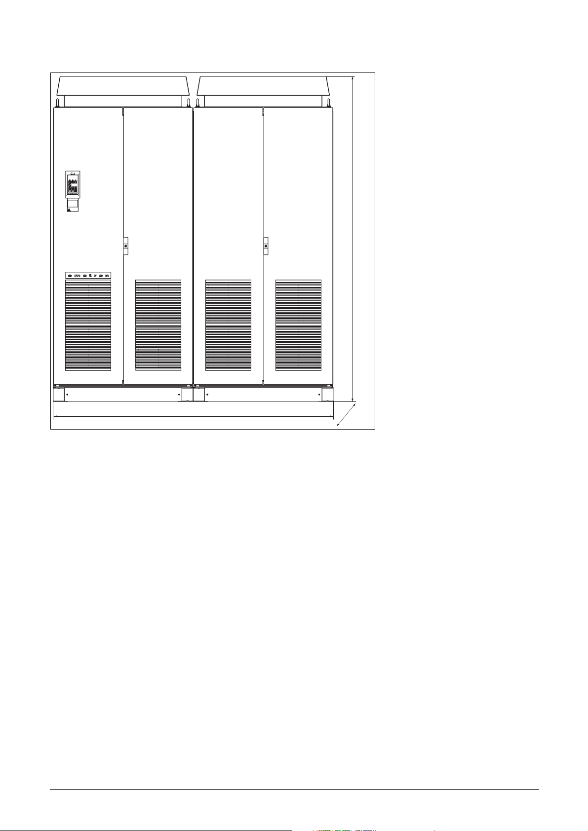
2.3 Cabinet mounting
2.3.1 Cooling
If the variable speed drive is installed in a cabinet, the rate of
airflow supplied by the cooling fans must be taken into consideration.
Table 5 Flow rates cooling fans
FDU Model Flow rate [m3/hour]
003 – 013 40
018 – 037 150
046 – 073 165
090 – 175 510
210 – 250 800
300 – 375 1020
430 – 500 1600
600 – 750 2400
860 – 1k0 3200
1200 – 1500 4800
600
600
Fig. 15 VSD models 300 - 500 (G and H)
Emotron AB 01-3694-01r2 Mounting 13
2320
2320
1000
Fig. 16 VSD models 600 - 750 (I)
600
1200
Fig. 17 VSD models 860 - 1000 (J)
600
14 Mounting Emotron AB 01-3694-01r2
2320
2000
Fig. 18 VSD models 1200 - 1500 (K)
600
Emotron AB 01-3694-01r2 Mounting 15

16 Mounting Emotron AB 01-3694-01r2
3. Installation
The description of installation in this chapter complies with
the EMC standards and the Machine Directive.
Select cable type and screening according to the EMC
requirements valid for the environment where the VSD is
installed.
3.1 Before installation
Read the following checklist and think through your application before installation.
• External or internal control.
• Long motor cables (>100m).
• Motors in parallel.
• Functions.
• Suitable VSD size in proportion to the motor/applica-
tion.
• Mount separately supplied option boards according to
the instructions in the appropriate option manual.
If the VSD is temporarily stored before being connected,
please check the technical data for environmental conditions. If the VSD is moved from a cold storage room to the
room where it is to be installed, condensation can form on
it. Allow the VSD to become fully acclimatised and wait
until any visible condensation has evaporated before connecting the mains voltage.
3.2 Cable connections
• Dimension the cables and fuses in accordance with the
nominal output current of the motor. See table 43, page
162.
• Keep the motor cable between VSD and motor as short
as possible.
• The screening must be connected with a large contact
surface of preferable 360× and always at both ends, to
the motor housing and the VSD housing. When painted
mounting plates are used, do not be afraid to scrape
away the paint to obtain as large contact surface as possible at all mounting points for items such as saddles and
the bare cable screening. Relying just on the connection
made by the screw thread is not sufficient.
NOTE: It is important that the motor housing has the
same earth potential as the other parts of the machine.
• The litz connection is only necessary if the mounting
plate is painted. All the variable speed drives have an
unpainted back side and are therefore suitable for
mounting on an unpainted mounting plate.
Connect the motor cables according to U - U, V - V and
W - W.
OPTION
DC
L2 L3 PEL1 U V WR
DC
-
+
3.2.1 Motor cables
To comply with the EMC emission standards the variable
speed drive is provided with a RFI mains filter. The motor
cables must also be screened and connected on both sides. In
this way a so-called “Faraday cage” is created around the
VSD, motor cables and motor. The RFI currents are now
fed back to their source (the IGBTs) so the system stays
within the emission levels.
Recommendations for selecting motor
cables
• Use screened cables according to specification in table 7.
Use symmetrical shielded cable; three phase conductors
and a concentric or otherwise symmetrically constructed
PE conductor, and a shield.
• When the conductivity of the cable shield is <50% of the
conductivity of the phase conductor, a separate PE conductor is required.
• Use heat-resistant cables, +60°C or higher.
Fig. 19
Switches between the motor and the
VSD
If the motor cables are to be interrupted by maintenance
switches, output coils, etc., it is necessary that the screening
is continued by using metal housing, metal mounting plates,
etc. as shown in the Fig. 21.
Fig. 22 shows an example when there is no metal mounting
plate used (e.g. if IP54 variable speed drives are used). It is
important to keep the “circuit” closed, by using metal housing and cable glands.
Emotron AB 01-3694-01r2 Installation 17

VSD built into cabinet
r
O
Screening of motor cable
Screening of signal cables
Fig. 20 Screening of cables for models 018 - 037.
Pay special attention to the following points:
• If paint must be removed, steps must be taken to prevent
subsequent corrosion. Repaint after making connections!
• The fastening of the whole variable speed drive housing
must be electrically connected with the mounting plate
over an area which is as large as possible. For this purpose
the removal of paint is necessary. An alternative method
is to connect the variable speed drive housing to the
mounting plate with as short a length of litz wire as possible.
• Try to avoid interruptions in the screening wherever possible.
RFI-Filter
(option)
Mains
Litze
Mains
(L1,L2,L3,PE)
VSD
Motor
Metal coupling
nut
Brake resisto
(option)
Metal cable glands
Output coil (option)
Screened cables
Unpainted mounting
plate
Metal connector housing
Motor
Fig. 21 Variable speed drive in a cabinet on a mounting plate
Fig. 22 shows an example when there is no metal mounting
plate used (e.g. if IP54 variable speed drives are used). It is
important to keep the “circuit” closed, by using metal housing and cable glands.
• If the variable speed drive is mounted in a standard cabinet, the internal wiring must comply with the EMC
standard. Fig. 21 shows an example of a VSD built into a
cabinet.
VSD
RFI-Filter
Mains
Metal cable glands
Screened cables
Metal housing
utput
coils
(option)
Metal connector housing
Motor
Metal cable gland
Mains
Brake
resistor
(option)
Fig. 22 Variable speed drive as stand alone
18 Installation Emotron AB 01-3694-01r2
Placing of motor cables
Keep the motor cables as far away from other cables as possible, especially from control signals. The minimum distance
between motor cables and control cables is 30 cm.
Avoid placing the motor cables in parallel with other cables.
The power cables should cross other cables at an angle of
90°.
Long motor cables
If the connection to the motor is longer than 100 m (40 m
for models 003-013), it is possible that capacitive current
peaks will cause tripping at overcurrent. Using output coils
can prevent this. Contact the supplier for appropriate coils.
Switching in motor cables
Switching in the motor connections is not advisable. In the
event that it cannot be avoided (e.g. emergency or maintenance switches) only switch if the current is zero. If this is
not done, the VSD can trip as a result of current peaks.
3.2.2 Mains cables
Dimension the mains and motor cables according to local
regulations. The cable must be able to carry the VSD load
current.
Recommendations for selecting mains
cables
• To fulfil EMC purposes it is not necessary to use
screened mains cables.
• Use heat-resistant cables, +60°C or higher.
• Dimension the cables and fuses in accordance with local
regulations and the nominal output current of the
motor. See table 43, page 162.
• The litz connection is only necessary if the mounting
plate is painted. All the variable speed drives have an
unpainted back side and are therefore suitable for
mounting on an unpainted mounting plate.
Connect the mains cables according to Fig. 23. The VSD
has a built-in RFI mains filter that complies with category
C3 which suits the Second Environment standard.
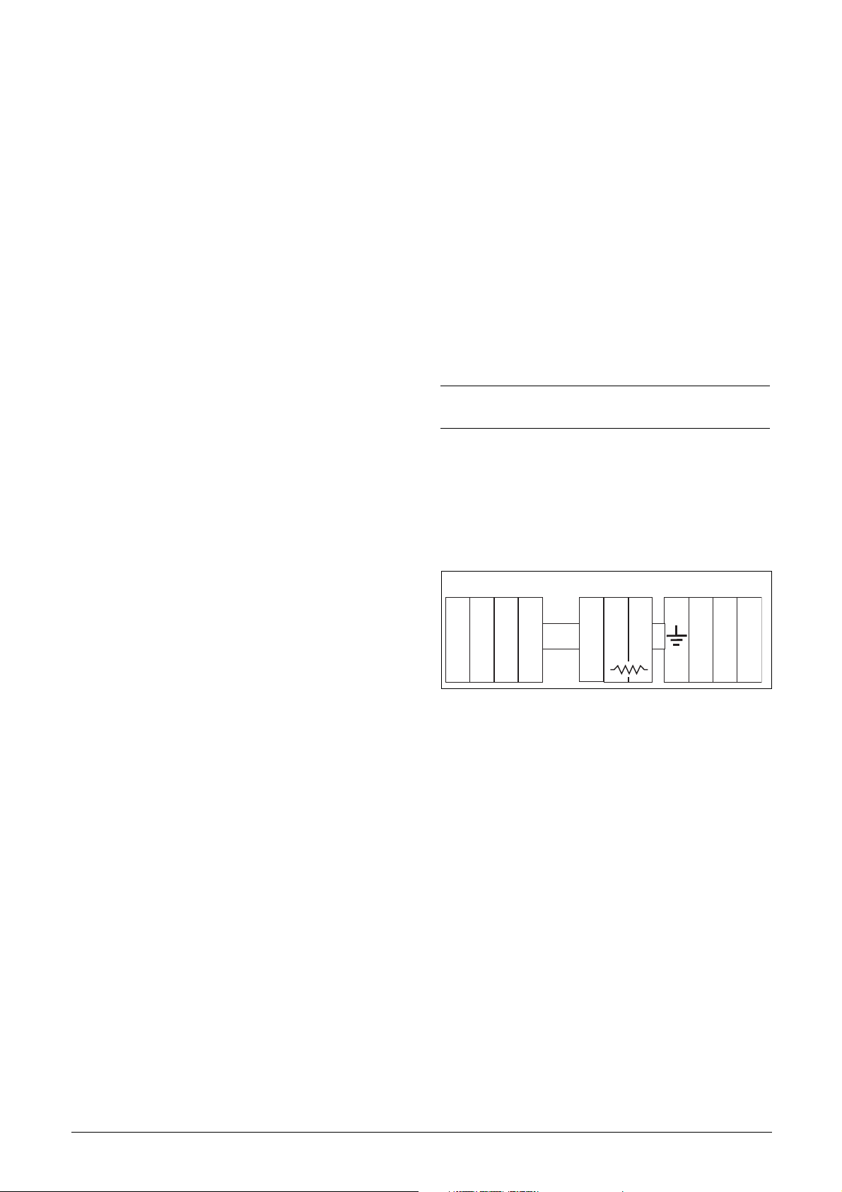
Table 6 Mains and motor connection
L1,L2,L3
PE
U, V, W
(DC-),DC+,R
NOTE: The Brake and DC-link Terminals are only fitted if
the Brake Chopper Option is built-in.
Mains supply, 3 -phase
Safety earth (protected earth)
Motor earth
Motor output, 3-phase
Brake resistor, DC-link
connections (optional)
WARNING: The Brake Resistor must be
connected between terminals DC+ and R.
WARNING: In order to work safely, the mains
earth must be connected to PE and the
motor earth to .
3.3 Cable specifications
Table 7 Cable specifications
Cable Cable specification
Mains
Motor
Control
Power cable suitable for fixed installation for the
voltage used.
Symmetrical three conductor cable with concentric protection (PE) wire or a four conductor cable
with compact low-impedance concentric shield
for the voltage used.
Control cable with low-impedance shield,
screened.
3.4 Stripping lengths
Fig. 24 indicates the recommended stripping lengths for
motor and mains cables.
Table 8 Stripping lengths for mains and motor cables
OPTION
Model
DC
L2 L3 PEL1 U V WR
Fig. 23 Mains and motor connections
Emotron AB 01-3694-01r2 Installation 19
DC
-
+
003–013 60 8 60 8 31
018–037 115 12 115 12 32
046–073 130 11 130 11 34
090-175 160 16 160 16 41
210–250 170 24 170 24 46
Mains cable Motor cable
a
(mm)b (mm)a (mm)b (mm)c (mm)
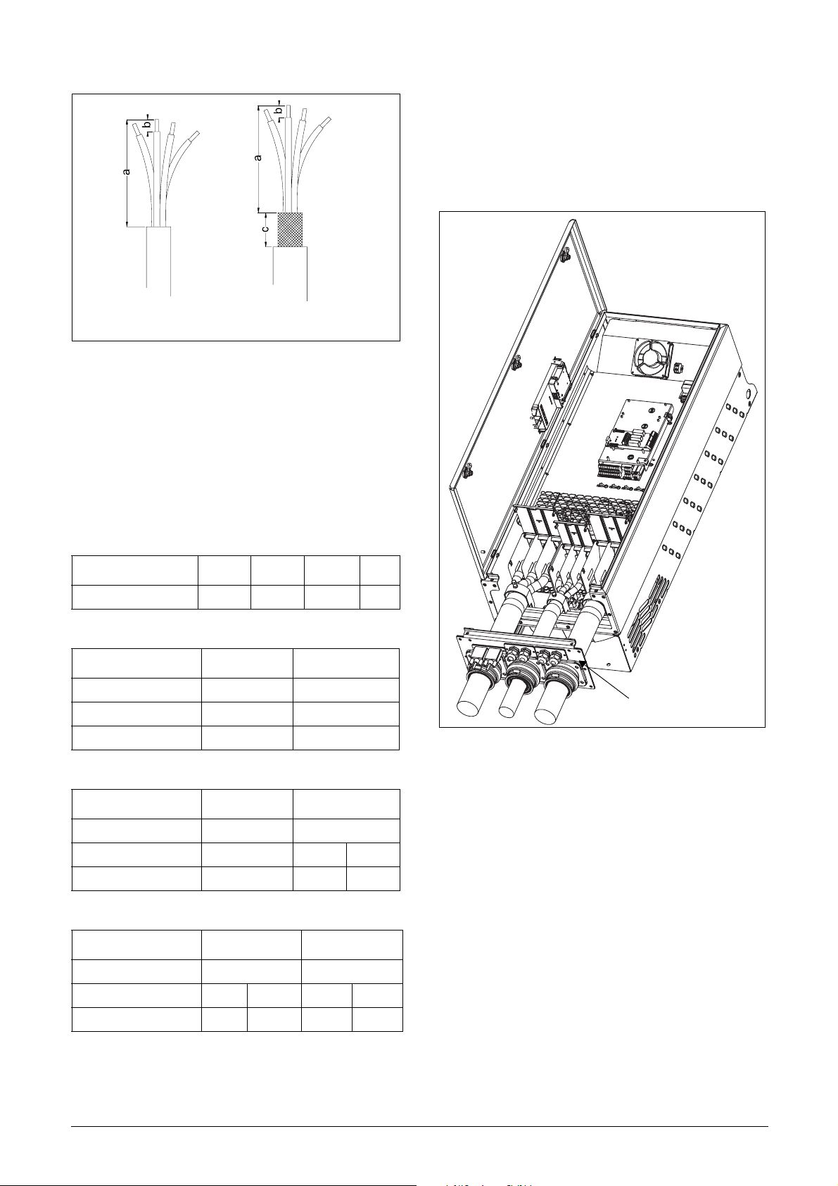
MotorMains
(06-F45-cables only)
Fig. 24 Stripping lengths for cables
3.4.1 Dimension of cables and fuses
Please refer to the chapter Technical data, section 14.7, page
162.
3.4.2 Tightening torque for mains and
motor cables
3.5 Connect motor and mains
cables
VSD model 090 to 250
To simplify the connection of thick motor and mains cables
to the VSD model 090-250 the cable interface can be
removed.
Table 9 Model 003 to 073
003-013 018-037 046-060 073
Tightening torque, Nm 0.5 1.5 1.5 3.2
Table 10 Model 90 to 109
Brake chopper Mains/motor
Block, mm
Cable diameter, mm
Tightening torque, Nm 14 14
2
2
95 95
16-95 35-95
Table 11 Model 146 to 175
Brake chopper Mains/motor
Block, mm
Cable diameter, mm
Tightening torque, Nm 14 14 24
2
2
95 150
16-95 35-95 120-150
Table 12 Model 210 to 250
Brake chopper Mains/motor
Block, mm
Cable diameter, mm
Tightening torque, Nm 14 24 14 24
2
2
150 240
35-95 120-150 35-70 95-240
Cable interface
Fig. 25 Connecting motor and mains cables
1. Remove the cable interface from the housing.
2. Put the cables through the glands.
3. Strip the cable according to Table 8.
4. Connect and tighten the cable in the clamp.
5. Put the cable interface in place and secure with the
screws.
20 Installation Emotron AB 01-3694-01r2
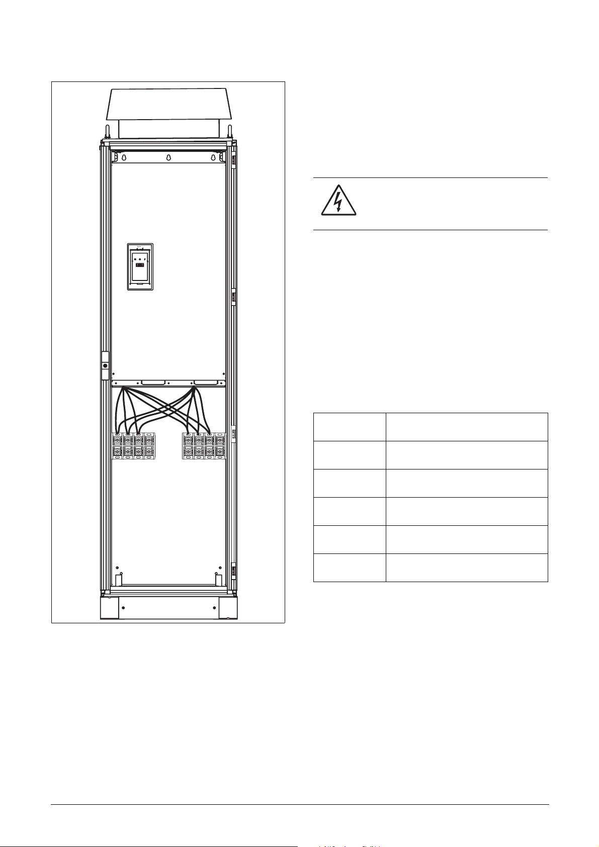
VSD model 300 to 1500
3.6 Thermal protection on the
motor
Standard motors are normally fitted with an internal fan.
The cooling capacity of this built-in fan is dependent on the
frequency of the motor. At low frequency, the cooling capacity will be insufficient for nominal loads. Please contact the
motor supplier for the cooling characteristics of the motor at
lower frequency.
WARNING: Depending on the cooling
characteristics of the motor, the application,
the speed and the load, it may be necessary
to use forced cooling on the motor.
Motor thermistors offer better thermal protection for the
motor. Depending on the type of motor thermistor fitted,
the optional PTC input may be used. The motor thermistor
gives a thermal protection independent of the speed of the
motor, thus of the speed of the motor fan. See the functions,
Motor I
2
t type [231] and Motor I2t current [232].
3.7 Motors in parallel
It is possible to have motors in parallel as long as the total
current does not exceed the nominal value of the VSD. The
following has to be taken into account when setting the
motor data:
L1 L2 L3 PE PE U V W
Fig. 26 Connecting motor and mains cables
VSD models 300 to 1500 are supplied with Klockner Moeller K3x240/4 power clamps.
For all type of wires to be connected the stripping length
should be 32 mm.
Menu [221]
Motor Voltage:
Menu [222]
Motor Frequency:
Menu [223]
Motor Power:
Menu [224]
Motor Current:
Menu [225]
Motor Speed:
Menu [227]
Motor Cos PHI:
The motors in parallel must have the
same motor voltage.
The motors in parallel must have the
same motor frequency.
Add the motor power values for the
motors in parallel.
Add the current for the motors in parallel.
Set the average speed for the motors in
parallel.
Set the average Cos PHI value for the
motors in parallel.
Emotron AB 01-3694-01r2 Installation 21

22 Installation Emotron AB 01-3694-01r2
4. Control Connections
4.1 Control board
Fig. 27 shows the layout of the control board which is where
the parts most important to the user are located. Although
the control board is galvanically isolated from the mains, for
safety reasons do not make changes while the mains supply
is on!
X5
X4
Communication
Option
WARNING: Always switch off the mains
voltage and wait at least 5 minutes to allow
the buffer capacitors to discharge before
connecting the control signals or changing
position of the switches.
X6
X7
I
12
1
X1
Fig. 27 Control board layout
Switches
S3 S4
S2S1
II
U
I
UU
X8
Control
Panel
U
Control
signals
22
11
X2
41
42 43
31 32
Relay outputs
33
X3
51
52
Emotron AB 01-3694-01r2 Control Connections 23
4.2 Terminal connections
The terminal strip for connecting the control signals is
accessible after opening the front panel.
The table describes the default functions for the signals. The
inputs and outputs are programmable for other functions as
described in chapter 11. page 63. For signal specifications
refer to chapter 14. page 157.
NOTE: The maximum total combined current for outputs
11, 20 and 21 is 100mA.
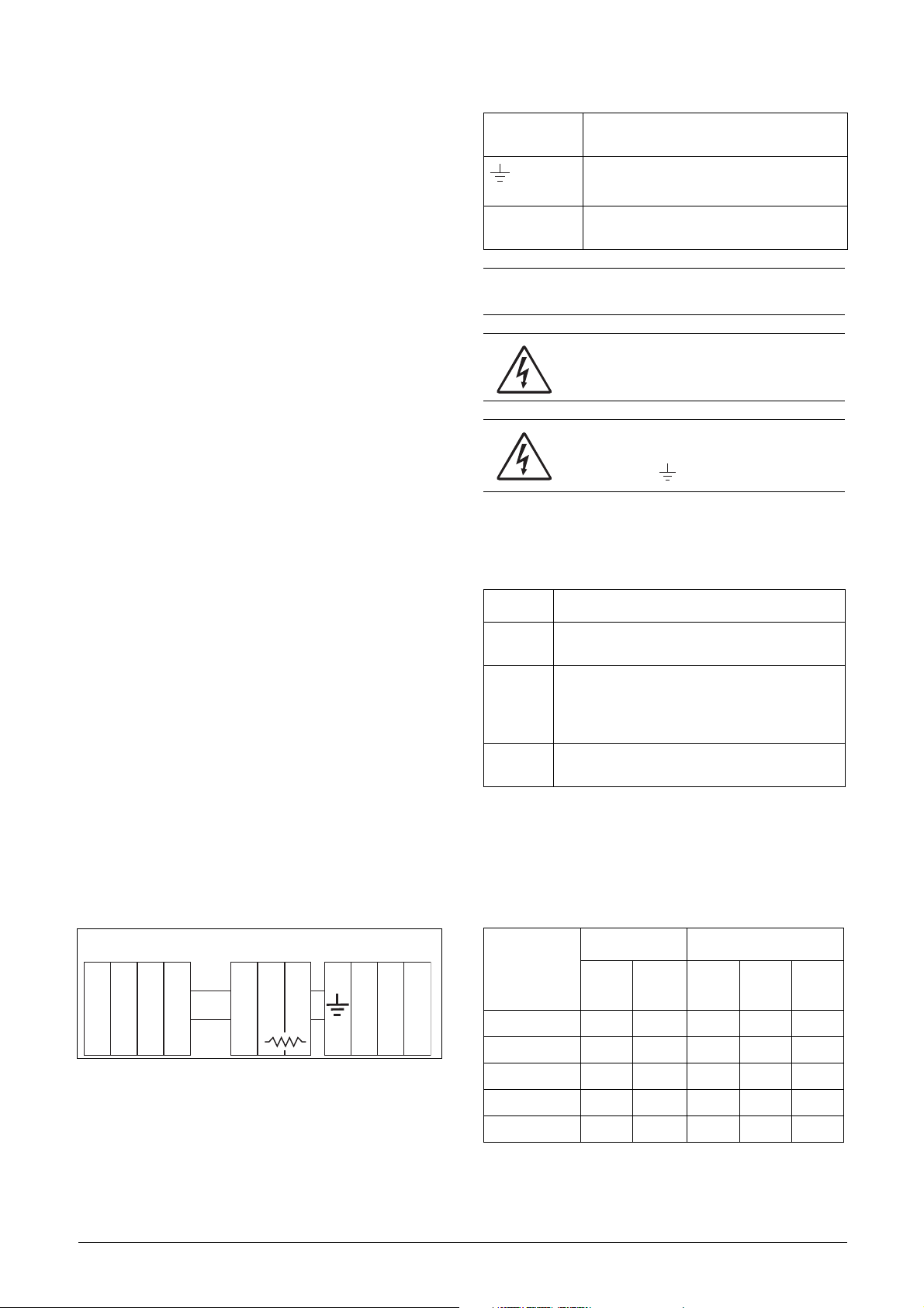
Table 13 Control signals
Terminal Name Function (Default)
Outputs
1 +10 V +10 VDC supply voltage
6 -10 V -10 VDC supply voltage
7 Common Signal ground
11 +24 V +24 VDC supply voltage
12 Common Signal ground
15 Common Signal ground
Digital inputs
8DigIn 1RunL (reverse)
9DigIn 2RunR (forward)
10 DigIn 3 Off
16 DigIn 4 Off
17 DigIn 5 Off
18 DigIn 6 Off
19 DigIn 7 Off
22 DigIn 8 RESET
Digital outputs
20 DigOut 1 Ready
21 DigOut 2 Brake
Analogue inputs
2AnIn 1Process Ref
3AnIn 2Off
4AnIn 3Off
5AnIn 4Off
Analogue outputs
13 Speed Min speed to max speed
14 Torque 0 to max torque
Relay outputs
31 N/C 1
32 COM 1
33 N/O 1
Relay 1 output
Trip, active when the VSD is in a
TRIP condition.
Table 13 Control signals
Terminal Name Function (Default)
41 N/C 2
42 COM 2
43 N/O 2
51 COM 3
52 N/O 3
NOTE: N/C is opened when the relay is active and N/O is
closed when the relay is active.
Relay 2 output
Run, active when the VSD is
started.
Relay 3 output
Off
24 Control Connections Emotron AB 01-3694-01r2
4.3 Connection example
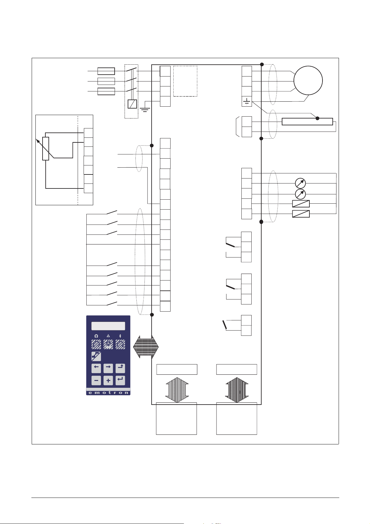
Fig. 28 gives an overall view of a VSD connection example.
L1L3L1
RFI-
L2
filter
PE
Alternative for
potentiometer control Optional
1
2
3
4
5
6
7
0 - 10 V
4 - 20 mA
+10 VDC
1
AnIn 1
2
AnIn 2
3
AnIn 3
4
AnIn 4
5
-10 VDC
6
Common
7
DigIn 1:RunL*
8
DigIn 2:RunR*
9
DigIn3
10
+24 VDC
11
Common
15
DigIn 4
16
DigIn 5
17
DigIn 6
18
DigIn 7
19
DigIn 8:Reset*
22
Common
AnOut 1
AnOut 2
DigOut 1
DigOut 2
Relay 1
Relay 2
U
V
W
DC+
R
12
13
21
14
20
21
31
32
33
41
42
43
Motor
PREV NEXT ESC
* Default setting
Fig. 28 Connection example
Relay 3
51
52
RESET
LOC/
REM
Comm. options
ENTER
Fieldbus option
or PC
Other options
Option board
NG_06-F27
Emotron AB 01-3694-01r2 Control Connections 25

4.4 Inputs configuration
4.5 Connecting the Control
with the switches
The switches S1 to S4 are used to set the input configuration
for the 4 analogue inputs AnIn1, AnIn2, AnIn3 and AnIn4
as described in table 14. See Fig. 27 for the location of the
switches.
Table 14 Switch settings
Input Signal type Switch
AnIn1
AnIn2
AnIn3
AnIn4
Voltage
Current (default)
Voltage
Current (default)
Voltage
Current (default)
Voltage
Current (default)
S1
S1
S2
S2
S3
S3
S4
S4
I
U
I
U
I
U
I
U
I
U
I
U
I
U
I
U
Signals
4.5.1 Cables
The standard control signal connections are suitable for
stranded flexible wire up to 1.5 mm
2.5 mm
2
.
2
and for solid wire up to
NOTE: Scaling and offset of AnIn1 - AnIn4 can be
configured using the software. See menus [512], [515],
[518] and [51B] in section 11.6, page 112.
NOTE: the 2 analogue outputs AnOut 1 and AnOut 2 can
be configured via the software. See menu [530]
section 11.6.3, page 119
Control signals
Fig. 29 Connecting the control signals
NOTE: The screening of control signal cables is
necessary to comply with the immunity levels given in
the EMC Directive (it reduces the noise level).
NOTE: Control cables must be separated from motor and
mains cables.
26 Control Connections Emotron AB 01-3694-01r2

4.5.2 Types of control signals
Always make a distinction between the different types of signals. Because the different types of signals can adversely
affect each other, use a separate cable for each type. This is
often more practical because, for example, the cable from a
pressure sensor may be connected directly to the variable
speed drive.
We can distinguish between the following types of control
signals:
4.5.4 Single-ended or double-ended
connection?
In principle, the same measures applied to motot cables
must be applied to all control signal cables, in accordance
with the EMC-Directives.
For all signal cables as mentioned in section 4.5.2 the best
results are obtained if the screening is connected to both
ends. See Fig. 30.
Analogue inputs
Voltage or current signals, (0-10 V, 0/4-20 mA) normally
used as control signals for speed, torque and PID feedback
signals.
Analogue outputs
Voltage or current signals, (0-10 V, 0/4-20 mA) which
change slowly or only occasionally in value. In general, these
are control or measurement signals.
Digital
Voltage or current signals (0-10 V, 0-24 V, 0/4-20 mA)
which can have only two values (high or low) and only occasionally change in value.
Data
Usually voltage signals (0-5 V, 0-10 V) which change rapidly
and at a high frequency, generally data signals such as
RS232, RS485, Profibus, etc.
Relay
Relay contacts (0-250 VAC) can switch highly inductive
loads (auxiliary relay, lamp, valve, brake, etc.).
Signal
type
Maximum wire size
Tightening
torque
Cable type
NOTE: Each installation must be examined carefully
before applying the proper EMC measurements.
Control board
Pressure
sensor
(example)
External control
(e.g. in metal housing)
Analogue Rigid cable:
Digital Screened
Data Screened
Relay Not screened
0.14-2.5 mm
Flexible cable:
0.14-1.5 mm
Cable with ferrule:
0.25-1.5 mm
2
2
2
0.5 Nm
Screened
Example:
The relay output from a variable speed drive which controls
an auxiliary relay can, at the moment of switching, form a
source of interference (emission) for a measurement signal
from, for example, a pressure sensor. Therefore it is advised
to separate wiring and screening to reduce disturbances.
4.5.3 Screening
For all signal cables the best results are obtained if the
screening is connected to both ends: the VSD side and the at
the source (e.g. PLC, or computer). See Fig. 30.
It is strongly recommended that the signal cables be allowed
to cross mains and motor cables at a 90° angle. Do not let
the signal cable go in parallel with the mains and motor
cable.
Control consol
Fig. 30 Electro Magnetic (EM) screening of control signal
cables.
Emotron AB 01-3694-01r2 Control Connections 27
 Loading...