

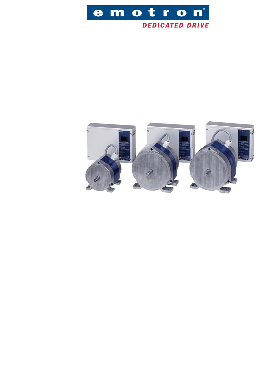
EMX™-R
DRIVE SYSTEM
INSTRUCTION MANUAL - English

Valid for the following models:
EMX-R-15S
EMX-R-15E
EMX-R-25S
EMX-R-25E
EMX-R-35S
EMX-R-35E
Version 2.x
EMX™-R
DRIVE SYSTEM
INSTRUCTION MANUAL - English
Document number: 01-3333-01
Edition: r2
Date of release: 2006-02-15
© Copyright Emotron AB 2005 - 2006
Emotron retain the right to change specifications and
illustrations in the text, without prior notification. The
contents of this document may not be copied without the
explicit permission of Emotron AB.

The product is protected as follows:
Patents: US 4 868 478; EP 0 285 637; SE 8604308-0
US 5 315 224; EP 0 507 835; SE 9002217-9
US 6 628 100; SE 9902821-9
SE 0100814-3
Registered design: US 462 937; DE 400 05 393.4; SE 66 630

Safety instructions
During installation
• Read the instruction manual completely before installation and commissioning.
• The installation must be carried out by qualified personnel.
• General conditions and regulations for the installation and operation of
electrical machinery must be observed.
• Measures to protect against personal injury and damage to the machine
must be taken following local rules and regulations.
• The drive system EMX-R is intended for permanent installation.
• Cables may not be connected or disconnected while the supply voltage is
on.
• Check that the equipment is correctly connected before it is taken into use,
see the instructions in the chapter on Mounting/Connection.
• Faults that arise due to faulty installation or operation are not covered by the
guarantee.
During operation
• Measurements in the control unit, during operation, must only be carried
out on the terminals and only by authorized personnel. NOTE! Great care
must be taken.
• The units may not be opened or disassembled during operation.
During disassembly and scrapping
• The housing of the control unit is made from aluminium and steel. The
material must be handled and recycled following the relevant laws.
• The circuit board contains small amounts of tin and lead, which must be
handled and recycled in accordance with the relevant laws.
• The motor is made from copper, plastic, aluminium and iron. These materials must be handled and recycled in accordance with the relevant laws.
Emotron AB 01-3333-01r2 1

2 Emotron AB 01-3333-01r2

Contents
1. Description.................................................................................. 5
1.1 Introduction................................................................................................. 5
1.2 Product range ............................................................................................. 5
1.3 Operating indicators / built-in functions ................................................... 6
1.3.1 Automatic purging mode / holding torque................................................ 7
1.3.2 Rotation monitor (DIP switch 4)................................................................. 8
1.3.3 Protection of the control unit ..................................................................... 9
2. Mounting/connection.............................................................. 11
2.1 Mounting .................................................................................................. 11
2.1.1 Sensor for rotation monitor..................................................................... 12
2.2 Connection ............................................................................................... 12
2.2.1 When switching off .................................................................................. 13
2.2.2 Recommendations with respect to EMC................................................ 13
2.2.3 Priority switch / defrosting / manual control......................................... 14
2.2.4 Manual control using a 10 kOhm potentiometer .................................. 14
2.2.5 Test switch ............................................................................................... 15
2.2.6 Choice of maximum speed ..................................................................... 17
2.2.7 Setting DIP switches ................................................................................ 18
2.2.8 Speed controller ...................................................................................... 19
2.2.9 Parallel connection .................................................................................. 19
2.2.10 Heat recovery on cooling – summer/winter switch............................... 20
2.2.11 Analogue output signal (only available on Model E) ............................. 20
2.2.12 Potentiometer with low resistance, 100 Ohm to 5 kOhm
(only available on Model E) ..................................................................... 20
3. Maintenance/troubleshooting................................................ 21
3.1 Maintenance ............................................................................................ 21
3.2 Motor diagnosis ....................................................................................... 21
3.3 Troubleshooting ....................................................................................... 22
Emotron AB 01-3333-01r2 3

4. Technical data ......................................................................... 25
4.1 The drive system’s operation using different control signals................ 26
4.2 Choice for sizes of drive system and belt pulley .................................... 29
4.3 Accessories and documentation ............................................................ 30
5. Appendix ................................................................................... 31
4 Emotron AB 01-3333-01r2

1. Description
1.1 Introduction
EMX-R is a series of speed controlled drive systems specially designed for driving rotary heat exchangers. The drive system consist of a motor and its associated control unit.
EMX-R completely replaces drive systems EMS-VVX 1, 2-4N, 2-4N/ET and
2-4EM as well as the drive systems EMS-VVX 15, 25 and 35. All mentioned
drive systems have completely been replaced by EMX-R.
The new drive system EMX-R is based, like its predecessor, on the SR-motors
(SR=Switched Reluctance). These motors make it possible to drive heat
exchanger rotors up to 3.5 metres in diameter without gears.
1.2 Product range
EMX-R is available in three sizes for rotors up to around 3.5 m. They come in
sizes 15, 25 and 35 (for other rotor sizes, please contact the local distributor or
Emotron AB).
The control unit is available in two versions, S and E, where Model E has an
extra circuit board for increased functionality. Built-in functions included in the
Model S are:
• Automatic purging operation
• Rotation monitor - integrated electronics or with external rotation sensor
• Alarm relay
•Test switch
• Priority switch/defrosting
• Heat recovery on cooling with external differential thermostat
In addition to the functions included in Model S, the Model E includes:
• Display of the rotor speed in r/min when the external rotation sensor is connected.
• Analogue output signal proportional to the speed of rotation of the motor.
• Heat recovery on cooling with external temperature sensors.
• Input for potentiometer with low resistance, 100 Ohm to 5 kOhm.
Emotron AB 01-3333-01r2 Description 5

• Prepared for serial communication.
1.3 Operating indicators / built-in functions
Two LEDs, one red and one green, are used on the Model S for indication,
while the Model E has an LED display as follows:
Table 1 Operating indication – Model S
Slow flashing – Purging mode/Low control signal
Green
Rapid flashing – Operation, the motor rotates continuously
Lit for two seconds – Magnet passing rotation sensor
Lit - RotoSens measures the load on the motor during acceleration
Lit or flashing LED indicates alarm, see also the chapter on troubles-
Red
hooting
Table 2 Operating indication – Model E
Purging mode. Low control signal
The speed of the rotor in rpm. At start a speed is displayed according to
the gear ratio rotor/motor = 1:25. After 2 pulses from the rotation monitor, the correct speed of rotation of the rotor is displayed. Range 0.2–99
rpm.
RotoSens is selected using the DIP-switch (4) and with no rotation sensor connected
Lit for two seconds when the magnet passes the rotation sensor
RotoSens measures the load on the motor during acceleration
Summer operation/heat recovery on cooling
No rotation monitor - DIP 4 in the OFF position and jumper 31-32
An alarm is indicated by the letter F followed by a number. See also the
chapter on troubleshooting.
6Description Emotron AB 01-3333-01r2

1.3.1 Automatic purging mode / holding torque
When the control signal is low, <1.5 V at 0–10 V, the drive system switches to
purging mode. In purging mode the motor shaft turns two revolutions every 10
minutes, which is equivalent to around 30 degrees of rotation by the heat
exchanger rotor. This slow rotation does not provide any significant heat transfer, but simply serves to keep the rotor clean.
Most of the time the rotor seals keep the rotor stationary, but if the rotor seals
are not touching the rotor and the air flow is not perpendicular to the rotor, the
air flow may cause the rotor to rotate. To prevent unintentional heat recovery in
this situation the motor is used to provide a holding torque to keep the rotor
stationary.
The first time the drive system goes into purging mode after the power is
switched on this holding torque is not activated, since many rotors do not
require an active holding torque to keep them stationary. A rotor that does
require a holding torque will then begin to turn slowly. The drive system immediately brakes this motion, reducing the speed to zero, and then applies a constant holding torque to keep the rotor stationary. The drive system has now
learned which rotors require a holding torque, and which do not. The holding
torque is at least 50% higher than the torque required for operation just before
is should stand still.
If a holding torque has been applied and you grasp the drive belt and try to turn
the rotor by hand, the torque will progressively increase.
The holding torque is generated by passing a current through one of the motor
phases. The higher the torque that is required, the higher the current. This current produces a noise that gets louder as the current increases. Integrated in the
control unit are three motor protection breakers, one for each motor phase. The
motor protection also protects the motor when the holding torque is activated.
Emotron AB 01-3333-01r2 Description 7

1.3.2 Rotation monitor (DIP switch 4)
Two different rotation monitors can be selected. The first, RotoSens™, which is
an integrated electronic rotation monitor, and secondly a rotation monitor
using a rotation sensor.
RotoSens uses the motor as the sensor. By allowing the control unit to measure
the load on the motor, you can determine whether the drive belt has broken.
When the drive belt has broken the motor load will be low. As the rotors which
rotate very easily also give a low load on the motor, it is necessary to also measure the load during acceleration - you then get a measurement of the rotor’s
moment of inertia. After 2 minutes of operation at a low load, a load measurement is made during acceleration. If the drive belt is broken an alarm is given, if
it is undamaged the load measurement during acceleration is repeated again
after 24 hours. In cleaning mode, measurement during acceleration is made
once every 24 hours.
The rotation monitor with sensor has a magnet fitted on the periphery of the
rotor. The magnet activates the sensor once every revolution. Should, for example, a belt break and the rotor stops, the pulses cease and an alarm is given. The
time until the alarm is given is speed dependent and is 24 seconds at max.
speed, 20 minutes at min. speed and about 8 hours in purge mode.
NOTE: In order to use RotoSens the load on the motor should not be to low.
The minimum diameter for the rotor and belt pulley for each size of the drive
system must be:
EMX-R-15: Belt pulley
EMX-R-25: Belt pulley ≥ 63 mm, Rotor diameter ≥ 1200 mm
EMX-R-35: Belt pulley ≥ 100 mm, Rotor diameter ≥ 2000 mm
If the belt pulley or rotor are smaller RotoSens can not be used, however,
the rotation monitor with sensor can always be used.
≥ 63 mm, Rotor diameter ≥ 630 mm
The rotation monitors give alarms through operating indications and via the
alarm relay, the motor does not stop with an alarm.
For operation without an external rotation sensor the DIP-switch 4 must be set
in position “OFF” (downwards), which means the built-in electronic rotation
monitor RotoSens is connected.
8Description Emotron AB 01-3333-01r2

For operation without both an external and the built-in electronic rotation
monitor RotoSens the DIP-switch 4 also must be set in position “OFF”, but
then a strap must be fitted between terminals 31 and 32.
1.3.3 Protection of the control unit
The control unit is protected by monitoring for both over-voltage and undervoltage. If the supply voltage goes over or under the allowed limits, the control
unit is disconnected and the motor stops. The motor starts again automatically
when the supply voltage returns to its normal value.
The control unit has built-in motor protection that protects against overloading, and external motor protection is not required. Power supply to the motor is
cut in the event of overload. In order to restart the drive system, the supply voltage to the control unit should be temporarily disconnected for at least 5 seconds.
Built-in short circuit protection protects against short circuits between the
phases of the motor and between the phases and earth.
Table 3 Protection and alarm functions
Protective
function
Supply fault, overvoltage
Supply fault,
under-voltage
Pre-alarm, rotation
monitor
Rotation
monitor
Pre-alarm, motor
protection/overload
Motor protection/
overload
Short circuit
1) RotoSens - manual, disconnect and reconnect the power supply.
Rotation monitor with sensor - automatic.
Emotron AB 01-3333-01r2 Description 9
External alarm
with alarm relay
Yes, immediately Automatic
No
Yes
No
Yes, immediately
Restart Alarm reset
Motor not stopped
The system tries
to reset three
times
Manual, disconnect and reconnect power
supply
Automatic
1)
Automatic
Manual, disconnect and reconnect power
supply

10 Description Emotron AB 01-3333-01r2

2. Mounting/connection
2.1 Mounting
Both the motor and the control unit are usually mounted in the heat exchanger
housing. In this way, they do not occupy any space outside of the heat
exchanger housing and are well protected during transport. Furthermore, it is
often advantageous from the point of view of interference (EMC) to place the
motor and control unit in the rotor housing. The motor is usually mounted on
a sprung motor support when a V-belt is used. In this way, problems arising if
non-circular rotors are used can be prevented. Vibration dampers should be
mounted between the motor and the motor support so that any vibration from
the motor is not transmitted to the rotor housing
.
Control unit
Motor
10-F08
Fig. 1 Rotor and drive system
Emotron AB 01-3333-01r2 Mounting/connection 11

2.1.1 Sensor for rotation monitor
The magnet for the rotation sensor is screwed onto the periphery of the heat
exchanger. If the rotor cover is magnetic, the magnet must be insulated from the
cover. The rotation sensor is mounted such that the magnet passes at a distance
of 5–8 mm, see below.
NOTE: Magnet and rotation sensor must not be mounted when RotoSens is
used, which means the built-in electronic rotation sensor is used, DIP-switch 4
is used. To display the rotor speed an external sensor must be used
(applicable for model E).
Magnet
Heat exchanger rotor
Rotation sensor
5-8 mm
Fig. 2 Mounting of the rotation sensor
2.2 Connection
WARNING! Residual voltage remains for up to 1 minute after
disconnection of the supply voltage.
The motor is delivered with a fixed connected motor cable to simplify installation of the drive system. The length of the cable is 2.0 m for EMX-R 15M and
2.5 m for EMX-R 25M and EMX-R 35M. The motor cable cannot be
extended because this could interfere with the electronic tachometer that is built
into the system.
12 Mounting/connection Emotron AB 01-3333-01r2

An external slow-blow fuse rated at 10 A must always be installed. The drive
system does not contain a fuse. Electronic motor protection is built into the
control unit, and monitors the motor at all times. The control unit is protected
from short circuit within the motor.
A safety switch is to be installed between the mains supply and the control unit.
An alarm for loss of power is given if the mains supply is disconnected.
WARNING! No switch is allowed between the motor and the control
unit.
2.2.1 When switching off
When it is desired to switch off the heat exchanger, for example at night, this
can be done using a relay connected in series with the control signal. This relay
interrupts the signal to control signal terminal number 33. In this way, no alarm
about interruption of power supply is given. The control signal can of course
also be reduced to its minimum value, in order to achieve the same result. If the
control signal is low or absent the drive system switches to purging mode.
2.2.2 Recommendations with respect to EMC
In order to fulfil the European EMC Directive 89/336/ECC regarding electromagnetic compatibility, the following precautions must be taken:
• The motor cable must be mounted as close to the heat exchanger housing as
possible. If the cable is too long, the excess should be collected together in
the form of, for example, a figure “8”. The area enclosed by the cable should
be as small as possible. Electrical tape or cable ties can be used to achieve
this.
Emotron AB 01-3333-01r2 Mounting/connection 13

WRONG RIGHT
Fig. 3 Excess motor cable should be arranged such that the area enclosed is as
small as possible
Special EMC couplings/glands are not necessary.
An EMC filter is built into all EMX-R models.
2.2.3 Priority switch / defrosting / manual control
A preselected speed of rotation can be specified by a potential-free connection
between the priority inputs 34–35. When terminal 34 is connected to terminal
35, the speed of rotation is determined by the priority potentiometer, which is
located next to the DIP switches in the control unit. The priority switch has
higher priority than the summer/winter switch (only available on Model E) and
the control signal.
The switch can be used, for example, when cleaning the rotor, defrosting using
an external differential pressostat or for manual control of the speed of rotation.
2.2.4 Manual control using a 10 kOhm potentiometer
It is simple to control the drive system manually using a 10 kOhm potentiometer connected as shown in the figure.
Control unit
33
34
10 kOhm
14 Mounting/connection Emotron AB 01-3333-01r2
37

2.2.5 Test switch
The control unit is equipped with a test switch, placed under the cover between
terminals 37 and 41. When this switch is in the “ON” position, the motor softstarts and the speed increases to the maximum, independently of other signal
sources. When in the “OFF” position (down), the test switch is not operational.
The test switch can also be used to run the motor at maximum speed if, for
example, an external control signal is available.
8
IU
J1
54
53
51
5556 57 58
52
Extra circuit board in
the Model E with LEDdisplay,
ON
ON
1
2
345678
L
N
31
32 33 343536
37 414243654321
E-terminals 51-58
and jumper J1
10-F05
1
2
56 7
34
Fig. 4 Location of terminals, etc.
No. Designation
1 Supply terminal
2Motor terminal
3 Priority potentiometer
4 Control signal terminal
5 DIP switch
Emotron AB 01-3333-01r2 Mounting/connection 15

No. Designation
y
6Test switch
7Alarm terminal
8 Operating indicator for Model S, two LEDS
Extra circuit board in
model E
51
52
Heat recovery on cooling
51-52 incoming air sensor
51-53 exhaust air sensor
Analogue output signal
0-10V/20mA
IU
J1
54
55
53
57
56
58
Potentiometer
control
34
35
36
Priority switch
Alarm relay 42-43
closed on alarm
41
42
37
Heat recover
on cooling
Model S and E
Modell S
L
N
L
N
Safety switch
32
31
3
4
2
1
M
6
5
Rotation
sensor
33
Control signal
10-F11
Fig. 5 Wiring diagram
16 Mounting/connection Emotron AB 01-3333-01r2
43

2.2.6 Choice of maximum speed
The maximum speed can be limited to 80% (200 rpm) or 60% (150 rpm). This
function is primarily intended for use with rotors smaller than 1.3 m, when it is
desired to limit the speed of rotation and/or when using larger belt pulleys.
Emotron AB 01-3333-01r2 Mounting/connection 17

2.2.7 Setting DIP switches
Control signal Speed controller
0-10 V
10 kOhm
1ON23
V-belt
2-10V Other belts
1ON23
0-20V
1ON23
Direction of rotation
Clockwise
4-20mA
1ON23
Counterclockwise
0-20mA
1ON23
Rotation monitor Maximum speed
With
rotation
sensor
ON
100%
4
ON
5
ON
5
ON
6
ON
6
ON
7 8
RotoSens 80%
ON
4
60%
ON
7 8
ON
7 8
WARNING! Disconnect the voltage supply before changing the DIP
switch settings.
18 Mounting/connection Emotron AB 01-3333-01r2

2.2.8 Speed controller
DIP switch 5 on the control unit can be used to select between two speed controllers. One controller provides gentler operation and is used if resilient belts
such as round belts, flat belts and resilient V-belts are fitted. In this case DIP
switch 5 should be set “OFF”. The other controller is faster and stiffer, and is
intended for use with stiff belts. In this case DIP switch 5 should be set “ON”.
If the stiffer controller is not adequate for smooth operation when the max.
speed is set to 100%, an even stiffer and faster controller can be selected by setting DIP switches 5 and 7 “ON” and setting DIP switch 8 “OFF”.
ON
5 7 8
2.2.9 Parallel connection
If several rotary heat exchangers are to be used in parallel using one control signal or sensor, each heat exchanger rotor must be equipped with its own drive
system (motor and control unit).
The control signal is connected to the first drive system according to the
instructions for connection. The other control units are connected by connecting terminals 33 and 34 of the other control units to terminals 33 and 34,
respectively, on the first control unit.
The DIP switches on the first control unit are set as described in “Setting DIP
switches”. DIP switch 1 and DIP switch 3 on the other control units are set as
described in “Setting DIP switches”, while DIP switch 2 is always set as
described below:
ON
2
The control units give individual alarms. The alarm outputs can be connected
in parallel or in series in order to obtain a collective alarm.
Model E can also use the analogue output signal in order to control other drive
systems. Terminals 54(-) and 55(+) are connected to terminals 34(–) and 33(+),
respectively. The DIP switches on all control units are set as described in “Setting DIP switches”.
Emotron AB 01-3333-01r2 Mounting/connection 19

2.2.10 Heat recovery on cooling – summer/winter switch
Heat recovery on cooling refers to the mode of operation when the incoming air
temperature exceeds the exhaust air temperature. By driving the rotary heat
exchanger at maximum speed, a cooling effect is achieved on the incoming air.
The heat recovery on cooling function is most simply obtained by using an
external regulator which has this function built-in. EMX-R is then controlled
by a control signal, e.g. 0–10 V.
If for example, an external regulator is already installed, you can obtain the heat
recovery on cooling function by directly connecting a separate differential thermostat to EMX-R, terminals 36–37
Model E has a built-in differential thermostat. This makes it possible to connect
two NTC sensors of resistance 2000 Ohm (for example EGL 511), one in the
incoming air duct and one in the exhaust air duct, directly to EMX-R, terminals
51–53. If the exhaust air is colder than the incoming air, the rotor rotates at its
maximum speed, and cooling is recovered. If the exhaust air is warmer than the
incoming air (as is normally the case) the speed is controlled by the control signal, and heat is recovered.
2.2.11 Analogue output signal (only available on Model E)
The output signal, 0–20 mA or 0–10 V, is proportional to the speed of the
motor. Maximum value, 20 mA or 10 V, is always obtained at the selected max.
speed (60, 80 or 100% of the motor’s maximum rpm). The choice between the
0–20 mA output signal and the 0–10 V output signal is made with jumper J1
positioned behind the control terminals 51–58.
2.2.12 Potentiometer with low resistance, 100 Ohm to 5
kOhm (only available on Model E)
When control is provided by a potentiometer with a total resistance value
between 100 Ohm and 5 kOhm, the three leads are connected to terminals 56–
58. DIP switches 1–3 are set in the same way as for a control signal of 0–10 V.
20 Mounting/connection Emotron AB 01-3333-01r2

3. Maintenance/troubleshooting
WARNING! Residual voltage remains for up to 1 minute after
disconnection of the supply voltage. The test switch and the DIP
switches may only be adjusted when the supply voltage has been
disconnected.
3.1 Maintenance
The motor and the controller do not normally require any maintenance. However, it should be regularly checked that the cabling is not damaged and that all
fixing screws are securely tightened.
3.2 Motor diagnosis
Disconnect the supply voltage. Disconnect the motor cables from the control
unit. Measure the motor resistance between 1–2, 3–4 and 5–6. The values
should be:
15M: 30–90 Ohm; 25M: 5–15 Ohm; 35M: 5–15 Ohm
The resistance should not differ by more than 5 Ohm between the phases for
15M, and by no more than 2 Ohm for 25M/35M. Also check the insulation
resistance between 1–3, 1–5, 3–5, 1–earth, 3–earth and 5–earth.
Emotron AB 01-3333-01r2 Maintenance/troubleshooting 21

3.3 Troubleshooting
Check that the equipment has been correctly installed, i.e. that the cables are
properly stripped, that there are no loose cables, etc., and check that the DIP
switches are correctly set.
It is always possible to test run the drive system using the TEST switch located
under the cover next to terminal 37, see Fig. 4. The switch has two fixed positions, when it is in the up position, the motor accelerates to its maximum speed
independent of the control signal, and when it is in the down position the rotation speed is controlled by the control signal.
If the motor does not reach maximum speed or respond to the control signal,
check DIP switches 1–3 and 7 and 8. If the heat exchanger rotates in the wrong
direction, change the setting of DIP switch 6. Reset, vibration, noise and builtin protection are described in the chapters Description and Mounting/Connection.
If the control unit is to be exchanged, the complete covered box containing the
circuit boards must be exchanged.
22 Maintenance/troubleshooting Emotron AB 01-3333-01r2

Table 4 Troubleshooting
Alarm indication
SEFault
Green LED
flashes
slowly
Red and
green LED
flash rapidly
Red LED
flashes
rapidly
Red LED is lit
and green
LED flashes
rapidly
Purging/
low control
signal
Pre-alarm
rotation
monitor
Rotation
monitor
Pre-alarm,
overload/
motor
protection
Fault condition/Action required
Check the EMX-R by running the drive system with the test switch located next to
terminal 37. The motor should accelerate
to its maximum speed. If the motor does
accelerate to the maximum speed when
the test switch is activated, the fault is
external.
Can 0–10 V (2–10 V) be measured
between 33(+) and 34 (-)?
Have + and - been swapped?
The drive system has switched to a softer
speed controller because the motor shaft
is jerking sharply. Check that the drive belt
is not slipping on the pulley.
The exchanger rotor does not rotate;
check the drive belt.
The rotor rotates; check that the indication
is given when the magnet passes the rotation sensor, see the section Operating
indicators, if not replace the rotation sensor. If RotoSens is used, check that the
rotor or belt pulley are not smaller than
630 mm respective 63 mm.
The motor protection has been activated
due to excessive load. After a cool-down
period of 10 minutes the system restarts
automatically. If the overload protection
trips 3 times within 120 minutes the drive
system will be shut down, see also overload (F5).
Emotron AB 01-3333-01r2 Maintenance/troubleshooting 23

Table 4 Troubleshooting
Alarm indication
SEFault
Overload/
Red LED is lit
No LED lit -
Red and
green flash
slowly and
alternately
Red and
green LED
flash rapidly
and alternately
Red LED
flashes
slowly
motor
protection
Supply voltage missing
Overvoltage The supply voltage exceeds 264 VAC.
Undervoltage
Earth fault in
the motor
Short circuit
in the motor
Circuit break
in the motor
Fault condition/Action required
The motor protection has been activated
due to excessive load. Check that the
motor cables are connected correctly, see
the chapter on Mounting/Connection.
Check also that the rotor runs freely and
that the diameters of the rotor and pulley
are not too large.
If the fault remains, carry out motor diagnosis. Replace the motor if it is faulty. If
the fault does not lie within the motor,
replace the control unit.
Check that 230 VAC ±15% is connected to
the supply terminal.
The supply voltage lies below 196 VAC.
Disconnect the supply voltage, check the
connection of the motor cable and check
that the correct motor is connected. If the
fault remains, carry out motor diagnosis.
If the motor is faulty, replace it. If the fault
does not lie with the motor, replace the
control unit.
24 Maintenance/troubleshooting Emotron AB 01-3333-01r2

4. Technical data
Table 5 Technical data
EMX-R
Function
15 25 35
Rotation speed [rpm] 5-250
1)
Tor que
Power [W] 40 100 160
Direction of rotation Selectable
Purging mode Built-in function
Motor protection Built-in function
Output data
Soft start and stop [s] 15/15 25/25 35/35
Alarm output Alternating contact, max 5 A 230 VAC
Supply voltage 230 VAC ±15%, 50/60 Hz
Current [A] 0.7 1.3 1.7
Control signal
Input data
Protection class IP 54
Weight, control unit [kg] 1.7
Weight, motor [kg] 5 8 11
Terminals 1 pc M12 and 4 pc M16 (glands)
Ambient temperature -30 - +40º C
General
Tac home ter
EMC, Emission EN 50081-1
EMC, Immunity EN 50082-2
1)
Torque is constant over entire speed range.
[Nm] 1.5 4 6
0–10 V, 2–10 V, 0–20V phase cut,
0–20 mA, 4–20 mA,
10 kOhm potentiometer
Electronic tachometer, tachometer cable is
not needed
Emotron AB 01-3333-01r2 Technical data 25

4.1 The drive system’s operation using
different control signals
The drive system has a built-in linearity function that gives a linear relationship
between the control signal and the efficiency of the heat exchanger rotor, rather
than having the speed of rotation proportional to the control signal. This provides good conditions for stable temperature control.
Motor speed [rpm]
Purging
2 rev./10 min.
250
200
150
5
Purging Max. Speed
100%
80%
60%
Control
signal
Control signal Purging Maximum speed
0-10 V 1,5 V 9,7 V
2-10 V 3 V 9,7 V
0-20 V 3 V 19,4 V
4-20 mA 6 mA 19,4 mA
0-20 mA 3 mA 19,4 mA
Table 6 Motor model designations
Article number Designation Notes
01-2160-00 EMX-R-15M Cable 2.0 m
01-2162-00 EMX-R-25M Cable 2.5 m
01-2163-00 EMX-R-35M Cable 2.5 m
26 Technical data Emotron AB 01-3333-01r2

K1
F
K2
K
FA
FC
FB
LC
HD
HA
H
10-F06
LA
HB
L
M
Fig. 6 Motor dimensions
Table 7 Motor dimensions (mm)
EMX-R F FA FB FC H HA HB HD
15 88 96 10 7 56 8 119 134
25 82 140 12 7 81 10 173 180
35 109 140 12 7 81 10 173 180
EMX-R K K1 K2 L LA LC M
15 14j6 5h9 20 113 30 145 110
25 14j6 5h9 20 114 35 152 160
35 14j6 5h9 20 141 35 179 160
Emotron AB 01-3333-01r2 Technical data 27

Table 8 Control unit model designations
Article number Designation
01-2170-11 EMX-R-15S
01-2171-11 EMX-R-15E
01-2174-11 EMX-R-25S
01-2175-11 EMX-R-25E
01-2176-11 EMX-R-35S
01-2177-11 EMX-R-35E
200
150
58
10-F07
6
29,5
113
188
ø 4,5 (4x)
Fig. 7 Control unit dimensions (mm)
28 Technical data Emotron AB 01-3333-01r2

4.2 Choice for sizes of drive system and belt
pulley
Table 9 Choice of size for drive system and belt pulley
Rotor
diameter
[mm]
700 15 63 60 13.5
700 15 30 100 10.7
900 15 63 60 10.5
900 15 40 100 11.1
1100 15 63 80 11.5
1100 15 50 100 11.4
1300 15 71 80 10.9
1300 15 63 100 12.1
1500 15 71 100 11.8
1700 25 80 100 11.8
1900 25 80 100 10.5
2100 25 100 100 11.9
2300 25 100 100 10.9
2500 25 100 100 10.0
2700 35 118 100 10.9
3100 35 140 100 11.3
3500 35 140 100 10.0
EMX-R
model
Belt pulley
diameter
[mm]
Maximum speed
of revolution
[%]
Rotor speed
[rpm]
NOTE: Higher rotor speeds than those given in the table above increase the
loading and a larger drive system may be necessary. Tight rotor seals may
also require the use of a larger size. Rotors that have a high capacity to
absorb humidity, such as dehumidification rotors in desiccant cooling
system requires a larger drive system, see separate documentation.
Emotron AB 01-3333-01r2 Technical data 29

4.3 Accessories and documentation
Table 10 Accessories
Article number Designation
01-2184-00 Rotation sensor with magnet M12 x 75 mm
01-3549-00 Rotation sensor with magnet M12 x 35 mm
01-2179-00 Cable fixture for control unit 15-35
01-2182-00 Mounting kit, expander type for motor 15-35
01-2183-00 Mounting kit 2*M6 for motor 15-35
01-2182-00
01-2183-00
Fig. 8 Mounting kits with vibration damping for motor
Table 11 Operating instructions
Article number Designation
01-3333-00 Swedish
01-3333-01 English
01-3333-02 German
01-3333-03 Dutch
01-3333-05 Danish
01-3333-06 Norwegian
01-3333-07 Finnish
01-3333-08 French
30 Technical data Emotron AB 01-3333-01r2

5. Appendix
Connection lable
Model E (optional)
51-52-53 Kylåtervinning, Heat recovery on cooling,
54-55 Analog ut, Analogue out, Analog aus
56-57-58 Pot. Styrning, Pot. Control, Pot. Betrieb
Kälterückgewinnung
IU
2
13
+
J1
1-2: 0-20mA
2-3: 0-10V
57565554535251 58
100ohm -
5kohm
Model S
Restspänning
Residual voltage
Restspannung
NÄT
MAINS
NETZ
NL
01-2271-00 R1
MOTOR
MOTOR
MOTOR
STYRSIGNAL
CONTROL SIGNAL
STEUERSIGNAL
0-10V
ON
12345678
2-10V
ON
12345678
4-20mA
ON
12345678
ROTATIONSVAKT
ROT. MONITOR
ROT. GEBER
Ja, Yes, Ja
ON
12345678
Nej, No, Nein
ON
12345678
31-32 Rotationsgivare, Rotation sensor,
Rotationsgeber
33-34 Styrsignal, Control signal,
Steuersignal
34-35 Prioritetomkopplare, Priority switch,
Prioritätsschalter
36-37 Kylåtervinning, Heat recovery on
cooling, Kälterückgewinnung
REMTYP
TYPE OF BELT
RIEMENTYP
ON
12345678
ON
12345678
654321NL37363534333231 434241
PRIORITETSPOT.
PRIORITY POT.
+
PRIORITÄT POT.
ROT. RIKTNING
ROT. DIRECTION
DREHRICHTUNG
ON
12345678
ON
12345678
TEST PÅ
TEST ON
TEST EIN
TEST AV
TEST OFF
TEST AUS
MAX. VARVTAL
MAX. RPM
MAX. DREHZAHL
100%
ON
12345678
80%
ON
12345678
60%
ON
12345678
LARM RELÄ
ALARM RELAY
ALARM RELAIS
42-43 Slutande vid larm
Closed on alarm
Geschlossen bei alarme
Emotron AB 01-3333-01r2 Appendix 31

32 Appendix Emotron AB 01-3333-01r2

Model S Model E
EMX-R
GRÖN GREEN GRÜN
Långsamt blinkande - Renblåsningsdrift
Snabbt blinkande - Drift
Lyser i 2 s - Magneten passerar
Slowly flashing - Cleaning operation
Fast flashing - Operation
Lit for 2 sec. - The magnet passes the
Langsam blinkend - Intervallbetrieb
Schnell blinkend - Betrieb
Leuchtet 2 Sek. lang - Rotormagnet passiert
RÖD RED ROT
Blinkande - Rotationslarm
Lyser - Överlast
Flashing - Rotation alarm
Lit - Overload
Blinkend - Rotationsalarm
Leuchtet - Überlast
VARNING! WARNING! ACHTUNG!
Bryt spänningen innan locket öppnas
Turn off supply before removing cover
Gerät vor dem Öffnen vom Netz trennen
rotationsgivaren
rotation sensor
Rotationsgeber
EMX-R
Integrerad elektr. rotationsvakt
Integrated electr. rotation monitor
Integriert elektr. Rotationswächter
Rotorvarvtal; Ext. rotationsgivare
Rotor speed; Ext. rotation sensor
Rotor Drehzahl; Ext. Rotationsgeber
Renblåsningsdrift
Cleaning operation
Intervallbetrieb
Signal från extern rotationsgivare
Signal from external rotation sensor
Signal von extern Rotationsgeber
Rotationslarm
Rotation alarm
Rotationsalarm
Överlast
Overload
Überlast
VARNING! WARNING! ACHTUNG!
Bryt spänningen innan locket öppnas
Turn off supply before removing cover
Gerät vor dem Öffnen vom Netz trennen

Emotron AB, Mörsaregatan 12, SE-250 24 Helsingborg, Sweden
Tel: +46 42 16 99 00, Fax: +46 42 16 99 49
E-mail: info@emotron.se
Internet: www.emotron.com
Emotron AB 01-3333-01r2 2006-02-15
 Loading...