

Page 1

uPA-2
STEREO
USER’S GUIDE
Page 2

Table of Contents
Safety Precautions 3
NEC (National Electrical Code) Standards
A Note for the Cable Television (CATV) Installer 5
Antenna Grounding Outside the House 5
Thank You for your UPA-2 Purchase 6
Unpacking the UPA-2
Inventory 7
Recording the Serial Number 7
Emotiva UPA-2 Two Channel Amplifier
Professional 250 Watt Amplifier Features
7
8
Front Panel Layout 8
Rear Panel Layout 9
Installation and Connections 10
AC Power Considerations 10
Physical Placement 10
Input Connection Considerations 11
5
8
Output Connection Considerations 11
Connection Tips for Superior Sound 11
Connection Diagrams 12
Connecting a 7.1 Preamp/Processor
Connection using a 7.1 channel preout to UPA-2
12V Trigger Connections 14
Speaker Output Connections 14
Series and Parallel Speaker Connections
13
13
15
Page 3

Series
Parallel
Technical Note about Multiple Speaker Connections
15
15
16
Troubleshooting Guide
No Sound (from one or more speakers connected to the
The amplifier shuts down often or the line circuit breaker trips often 17
Poor Bass Performance From Full Range Speakers connected to the
Turn-on and turn-off thumps
“Hum” Noises in the Speakers
Other Probable Causes of Noise
One or more RED lights on the Front Panel are Blinking
Problems with the whole A/V System
UPA-2 Technical Specifi cations
UPA-2)
UPA-2
Limited Warranty
Service Assistance for the
Emotiva Disclosure
UPA-2
17
17
17
18
18
19
19
19
20
21
21
21
Page 4
Safety Precautions
Read this User’s Guide thoroughly before attempting to install and configure the Emotiva UPA2 Amplifier. All the safety and operation instructions should be read before any operation of the
component(s) begin. After successful installation and configuration of the Emotiva UPA-2 Amplifier, be
sure to retain this manual in a safe place for any future reference needs.
All warnings on the Emotiva UPA-2 Amplifier and in these operating instructions should
be followed. Safety is a key component to a long lasting and trouble free installation.
The vast majority of the subsequent safety precautions involve simple common sense. If
you are not comfortable with the installation of audio/video entertainment equipment, it
will be to your benefit to seek the services of a qualified installation professional.
NEVER use the UPA-2 Amplifier near water such as a bathtub, washbowl, kitchen sink, laundry tub,
in a wet basement, or near a swimming pool, etc. There is a risk of electric shock to your body and
permanent damage to the equipment. Electric shock may result in permanent bodily injury or death.
The Emotiva UPA-2 Amplifier should be situated so that its location or installation position does not
interfere with proper ventilation. The Emotiva UPA-2 Amplifier should not be situated on a bed, sofa,
rug, or similar surface that may block any ventilation openings; or placed in a built-in installation such
as a bookcase, cabinet, or closed equipment rack that may impede the flow of air through ventilation
openings. If installed in a closed equipment rack for custom installations, be sure to add forced air
ventilation so that it has adequate air circulation. The Emotiva UPA-2 Amplifier should be situated
away from heat sources such as radiators, or any other devices which produce heat.
The Emotiva UPA-2 Amplifier should be connected to a power supply only of the type described in this
User’s Guide and what is labeled on the UPA-2 component. Power supply cords should be routed so
that they are not in high foot traffic areas or pinched by items placed upon or against them, paying
particular attention to cords at the wall plugs, convenience receptacles, and the point where they
connect into the UPA-2 Amplifier. The power cord of the UPA-2 Amplifier should be unplugged from the
outlet when unused for a long period of time. When it’s time for cleaning the Emotiva UPA-2 Amplifier,
it should be cleaned only as recommended in this User’s Guide. Never spray liquids directly into the
component’s vent openings. Care should be taken so that small objects do not fall into the inside of
the UPA-2 Amplifier.
The following situations require your Emotiva UPA-2 Amplifier is serviced only by qualified service
personnel:
1. The power-supply cord or the plug has been damaged; or
2. Objects have fallen, or liquid has spilled into the component; or
3. The UPA-2 has been exposed to rain; or
4. The UPA-2 does not appear to operate normally or exhibits a marked change in
performance; or
5. The UPA-2 has been dropped, or its enclosure or chassis is damaged.
Page 3
Page 5
The user should not attempt to service the UPA-2 Amplifier beyond the means described in this
Owner’s Guide. All other servicing should be referred to qualified service personnel.
To prevent electric shock, do not use this polarized plug with an extension cord,
receptacle or other outlet unless the blades can be fully inserted to prevent blade
exposure.
Pour preevenir les chocs electriques ne pas utiliser cette fi che polarises avec un
prolongateur, un prise de courant ou une autre sortie de cou rant, sauf si les lames
peuvent titre inserees a fond sans laisser aucune parIIIe a decouvert.
Grounding or Polarization — Precautions should be taken so that the grounding or polarization
means of the component is not defeated.
This apparatus does not exceed the Class A/Class B (whichever is applicable) limits for radio noise
emissions from digital apparatus as set out in the radio interference regulations of the Canadian
Department of Communications.
ATTENTION — Le present appareil numerique n’emet pas de bruits radioelectriques depassant las
limites applicables aux appareils numeriques de class A/de class B (selon le cas) prescrites dans le
reglement sur le brouillage radioelectrique edicts par les ministere des communications du Canada.
For questions regarding service, please contact:
Toll Free - (877) EMO-TECH (877) EMO-TECH(877) EMO-TECH
Website - www.emotiva.com
WARNING TO REDUCE THE RISK OF FIRE OR ELECTRIC SHOCK, DO N
CAUTION : TO PREVE
ATTENTION : POUR EVITER LES CHOCS ELECTRIQUES, INTRODUIRE LA LAME LA
PLUS LARGE DE LA FICHE DANS LA BORNE CORRESPONDANTE DE LA PRISEET
:
EXPOSE THI
S APPLIANCE TO RAIN OR MOISTUR
NT ELECTRIC SHOCK, MATCH WIDE BLADE OF PLUG TO
WIDE SLOT, FULLY INSERT.
POUSSER JUSQU’AU FON
D.
T
O
E
.
Page 4
Page 6
NEC (National Electrical Code) Standards
A Note for the Cable Television (CATV) Installer
This reminder is to call the CATV system installer’s attention to Article 820-40 of the NEC that
provides guidelines for proper grounding and in particular, specifies that the cable ground shall be
connected to the grounding system of the building as close to the point of cable entry as practical.
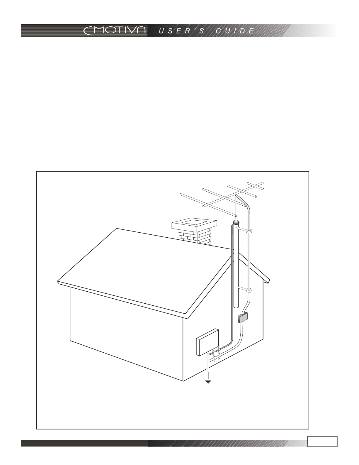
Antenna Grounding Outside the House
If an outside antenna is connected to the receiver, be sure the antenna system is grounded so as to
provide some protection against voltage surges and built-up static charges. Article 810 of the National
Electrical Code, ANSI/NFPA 70, provides information with regard to proper grounding of the leadin wire to an antenna-discharge unit, connection to grounding electrodes, and requirements for the
grounding electrode. See diagram below.
Always observe proper antenna or satellite dish grounding techniques. When lightning strikes
there is always the possibility that your antenna or dish (mounted high on the roof) can
become a conduit for lightning and electrically damage any equipment to which it’s connected.
Additionally, proper grounding offers safety to the people using the audio/video system in the
event of an electrical problem.
Page 5
Page 7
Thank You for your UPA-2 Purchase
Dear Home Entertainment Enthusiast,
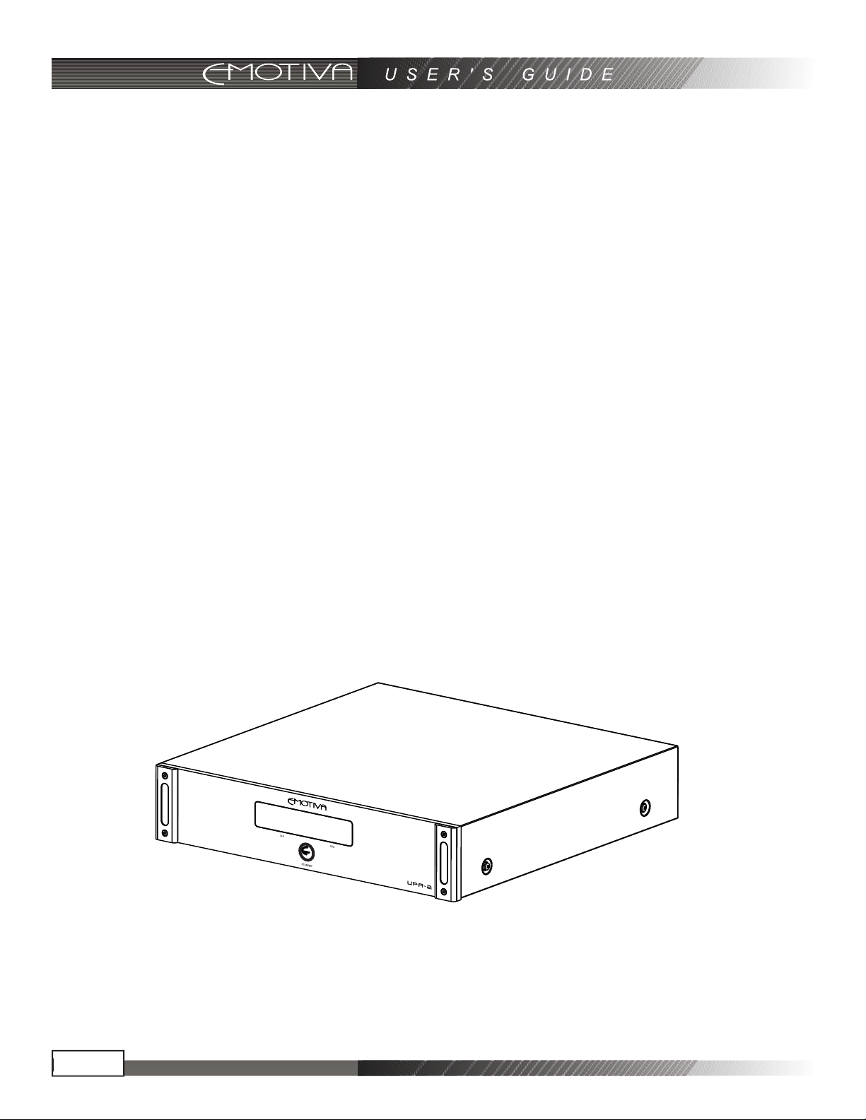
Thank you for purchasing the Emotiva UPA-2 Amplifier. We sincerely believe that it offers you
outstanding performance and value. Emotiva products are engineered and produced with the highest
quality materials and incorporate the latest technology. We think you will find the Emotiva UPA-2
meets or exceeds your expectations.
The Emotiva UPA-2 is a flexible, high performance amplifier. It has been designed for maximum
performance, ease of use, and installation flexibility. By employing cutting edge technology, the
Emotiva UPA-2 easily power to your speakers at high power levels, at the same time remaining as
efficient as possible, regardless of volume levels. This allows you to fully enjoy audio and video
sources without concern for dynamic headroom during complex musical passages and high level
effects. What’s more, the Emotiva UPA-2 does it all with exceptionally refined cosmetics and a sound
quality that will satisfy even the most discriminating tastes.
The Emotiva UPA-2 features an array of leading edge technologies and all the features necessary
to perform the functions expected of a high end power amplifier.
The Emotiva UPA-2 power amplifier is a rock solid component .
At Emotiva, we remember that creating home audio/video products means that they should be
easy to use while delivering unparalleled performance.
Page 6
Page 8
Unpacking the UPA-2
The Emotiva UPA-2 Amplifier should reach you in flawless condition. If you notice any shipping
damage or other issues upon unpacking the unit, please contact your Emotiva Retailer immediately.
Inventory
Included with your UPA-2 amplifier should be an IEC Class 1, 2 prong power cord, and this User’s
Guide. Please take a moment to make sure all the items are there in the packaging.
Gently lift out the unit and remove all the packing material and accessories. This amplifier is heavy,
so please unpack it carefully to avoid unnecessary injury or damage to the amplifier. It is important
to save all the packing materials and the box in case your Emotiva UPA-2 ever needs to be moved or
shipped back to the factory for service.
Make sure that you keep your sales receipt. It is the only way for Emotiva to establish the duration of
your Limited Warranty and it may come in useful for insurance purposes.
Recording the Serial Number
Please read the serial number located on the rear panel, and record it below. Also record the place
where you purchased this product and the date of purchase.
Model Number
Serial Number
Place of Purchase
Date of Purchase
UPA-2
Page 7
Page 9
Emotiva UPA-2 Stereo Power Amp lifier
Professional 250 Watt Amplifier Features
• Audiophile Quality Stereo Power Amplifier
• Two125 watt channels of Amplification
• Low noise 300VA Toroidal power transformer
• Complementary, discrete power amplifi er design incorporating high current, high speed,
ON Semiconductor power devices
• Channel status indicators for standby, operate, and fault
• Completely stable into 4 ohm loads
• Signal to Noise Ratio is greater than 100dB, unweighted reference full output
• THD .03% at rated power, 20Hz – 20kHz
• Fully protected from all fault conditions
• Soft start circuitry
• External trigger turn on
• Soft touch power switch
• 2RU chassis with solid milled faceplate
• IEC power inlet, 115/230 VAC Auto confi gurable
Front Panel Layout
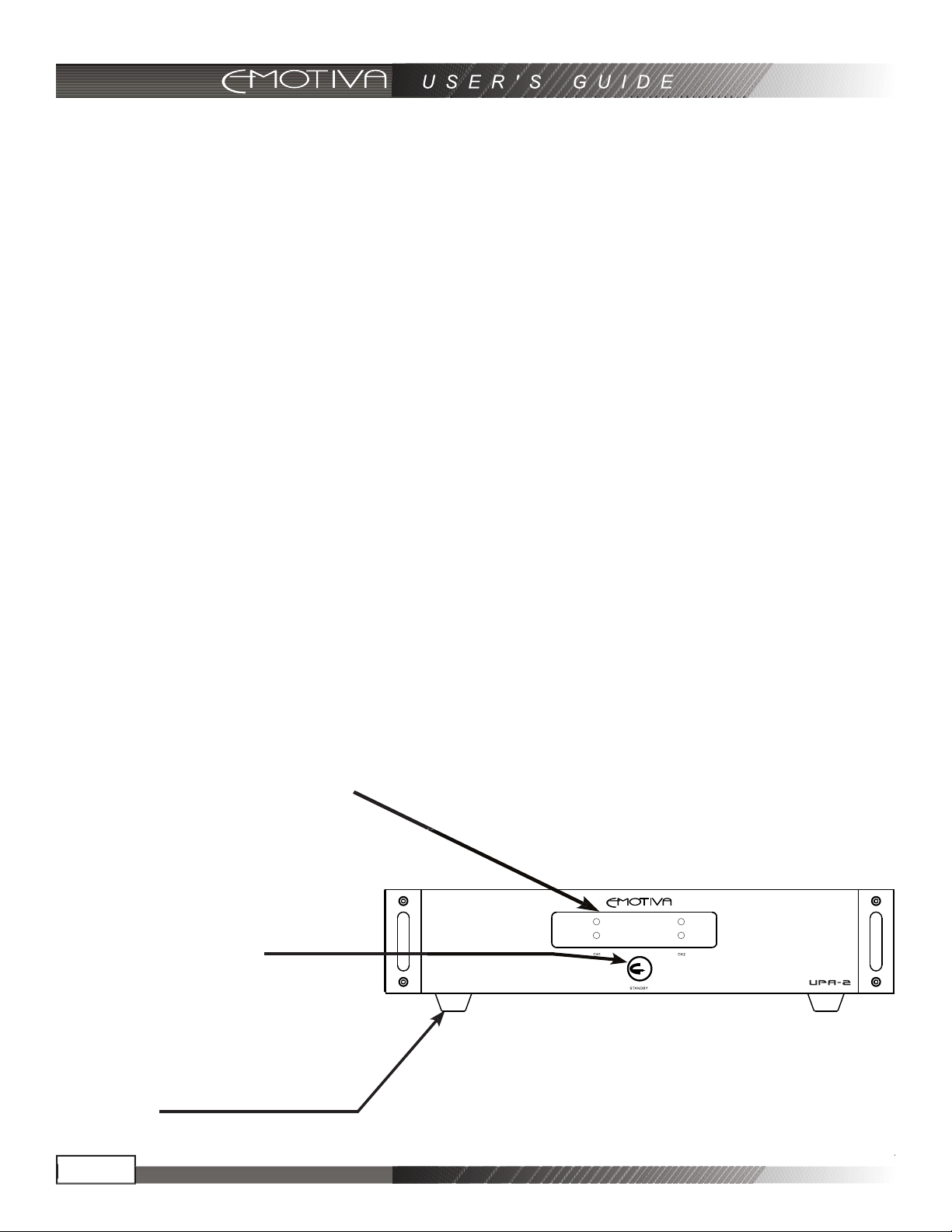
Front Panel LED Display
The front panel display contains Status LED lighting to indicate the condition of the UPA-2.
NO LED = Amplifier is OFF
BLUE LED = Normal Operation
FLASHING RED LED = Fault Condition
See “Troubleshooting” section for details.
Front Panel Power Switch
This switch provides the ON/OFF control of the
UPA-2 from the front panel. When the unit is
off and in standby mode, the switch illuminates
amber. Automatic switching is accomplished
with the 3.5mm trigger input on the back panel
using a 5-12VDC control signal.
Rubber Feet
These rubber feet keep the UPA-2 elevated for bottom ventilation as well as for vibration isolation.
Page8
Page 10
Rear Panel Layout
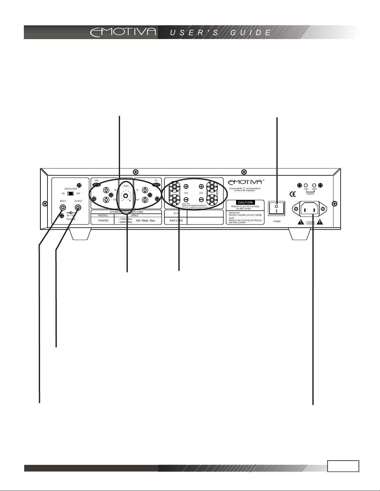
RCA Audio Inputs/Outputs
These inputs are for signal input
for each channel on the UPA-2. Simply
connect the appropriate input to your
preamplifier/processor or other preamp
level audio device. Loop outputs and
inputs are paralleled.
Master Power Switch
This rocker switch provides the master power
for the UPA-2. After it is in the ON position, the
amplifier can be turned on manually from the
front panel switch or automatically with the
trigger input via 3.5mm input jack.
Level Control
When set to Minimum,the
amplifier has no output;when
set to Maximum, it has 32dB of
gain and will match the gain
structure of all the other Emotive
Amplifiers.(Note:Loop out is not
controlled by it.)
Remote Turn On Jack (output)
.
This 3.5mm jack accepts a +12 volt output for
remote activation of the other device. This mates
directly with the Emotiva products trigger in
and supplied cable. If building your own cable,
center is positive and outer shield is negative.
Remote Turn On Jack (input)
This 3.5mm jack accepts a 5-12 volt input for
remote activation of the UPA-2. This mates
directly with the Emotiva processor trigger out
and supplied cable. If building your own cable,
center is positive and outer shield is negative.
Speaker Outputs (5 way Binding Posts)
These are the speaker outputs. The 5 way
binding posts accept stripped speaker wire,
banana plugs (single or dual), or spade
connectors. Be sure to observe correct polarity
when connecting speakers and be sure that
the wires do not touch between positive and
negative terminals.
Power Receptacle
This is a standard IEC 2 prong power receptacle.
It is advised that this amplifier have a direct
connection to a wall outlet. Do not plug into a
“power strip”.
Page 9
Page 11

Installation and Connections
AC Power Considerations
Ensure that the unit is plugged into an outlet capable of supplying the correct voltage and current
specified for your model. Remember to account for the electrical power that other components will
require if they share a common wall socket or electrical circuit. The majority of household electrical
sockets in places other than the kitchen and garage are 15 amperes maximum. Most DVD players
and other source components are fairly low current items. When both two of the power modules
are driven, the Emotiva UPA-2 requires a minimum of 5 amperes @ 115 volts or 5 amperes@ 230
volts. It should be sufficient to allow the other devices such as preamplifiers and A/V source units
to share a wall socket, but power amplifiers such as the UPA-2 and a video display(big screen TV
or video projector) should be provided a SEPARATE electrical connection on a SEPARATE circuit.
As the UPA-2 has a minimum requirement that can consume nearly one entire circuit, please use a
second (separate) electrical connection for other devices. DO NOT plug the UPA-2 into a power strip
or extension cord unless the device is specifically designed and rated for high current use.
Refer to your preamplifier, A/V source component(s), and video display owner’s manuals to learn
the power requirements so you can safely plan your electrical power requirements for your home
entertainment system.
Upon powering up the UPA-2 with the front panel switch or via 3.5mm trigger input (switch on the
rear panel must be set to “ON”), you will notice the front panel LED lighting starts off red for 5 seconds
and then turns to blue.
operation. If you experience no LED light or a blinking red LED light while the amplifier is on during
(otherwise) normal operation, please refer to the troubleshooting section of this manual.
This indicates the amplifier is
“on”, functioning normally , and ready for
Physical Placement
Place the UPA-2 on a flat, level surface. Please distribute the weight equally on the four feet. Please
give this unit adequate ventilation for proper cooling when placing. If this unit is placed in a cabinet,
please make sure that the cabinet’s rear is open to fresh air and there are at least 6 inches of free air
space above the amplifier and 1 inch on each side. If the amplifier is located on a carpeted surface,
place a board under the amplifier’s feet. If the cabinet’s design will not accommodate an open rear,
install two small brushless DC fans (such as those used in computer cases) to provide continuous air
flow into and out of the cabinet.
Do NOT block the ventilation holes on the UPA-2. The UPA-2 is equipped with a massive torroidal
power transformer. This transformer generates a magnetic field that could induce a hum in a turntable
(particularly a turntable equipped with a moving coil cartridge). Do NOT place a turntable directly
above or directly adjacent to the UPA-2.
Before placing the UPA-2 on a shelf,verify that the weight bearing capacity of the shelf is 25 lbs
or greater. The amplifier is heavy and should be placed toward the bottom of an audio rack to
minimize the rack being unnecessarily top heavy.
Page 10
Page 12

Input Connection Considerations
Whenever possible, keep preamplifier level audio cables away from electrical power cords by at least
a few inches. It’ s more important with amplifiers as the AC power cords are carrying much more current
than other source and preamplifier components, which means there is a larger degree of noise or
“hum” potential with the amplifier power cord in close proximity.
Output Connection Considerations
The output connectors provided on each channel of the UPA-2 are standard “binding post” speaker
connectors with industry standard spacing. These are sometimes called 5-way binding posts because
of the many ways in which the speaker wire can connect into the posts. The posts can accept bare
wire, spade terminals, and dual or single banana connectors. Spade connections or banana plugs
ensure a simple, solid fit in the terminal whereas bare wire may be awkward when the terminal is
screwed down to compress the wire into place. Keep in mind that if you use “dual banana” plugs
and “stack” them, you will be creating a parallel connection. For more details on series and parallel
connections, see pages 15-16.
It is important to observe polarity so that the speaker wire connects to the red and black terminals
on the amplifier and the corresponding terminals at the speaker. Also make sure that the positive
speaker wires do not touch the negative speaker wires, or any chassis metal. This will cause a short
circuit and activate the protection circuitry.
Connection Tips for Superior Sound
Before setting up your new system, please consider the following:
• Always make sure the UPA-2 is turned off before making or changing ANY connections.
• Whenever possible, route the power cords away from the signal cables or speaker wires to prevent
any hum or interference heard in the speakers.
• Many RCA type patch cords can be a very tight fi t and there is usually a preferred method of getting
them off. Some have to be removed with a twisting action. Be gentle or you may damage the jacks
of your UPA-2, the cables themselves, or other components.
• Many audiophile signal cables are intended to be hooked up in one direction. If this is the case, the
cables will be marked with arrows the direction of signal fl ow.
• It is usual for the right channel RCA patch cord plugs to be red and the left channel connections
to be white, grey, or black (depending on the cable brand). RCA connectors that are gold will be
designated with a colored band to designate the channel.
Page 11
Page 13
Connection Diagrams
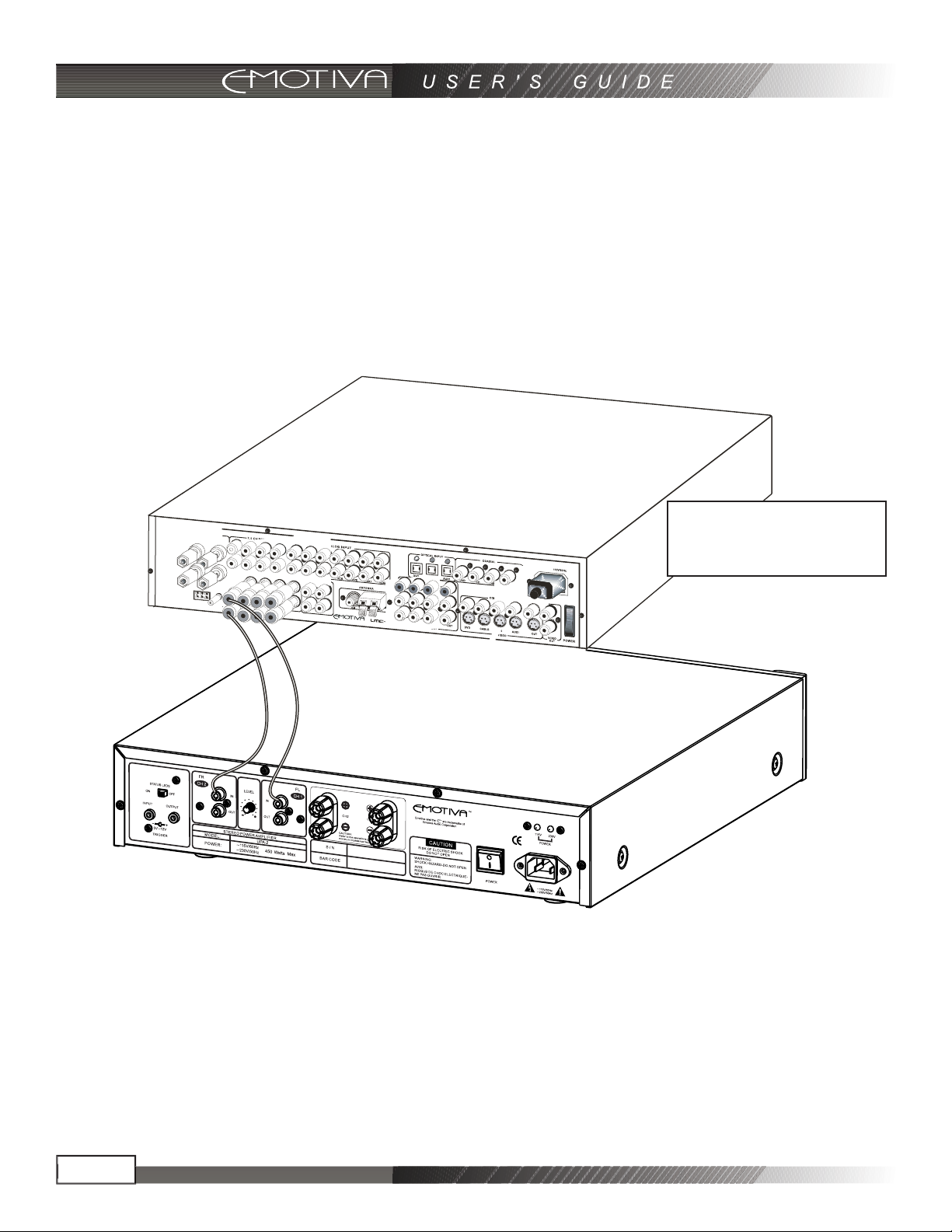
Connecting a 7.1 Preamp/Processor
Connection using a 7.1channel preout to
UPA-2
For details on connecting the
speakers to the 5 way binding
posts, please see Page 15
Page 12
Page 14
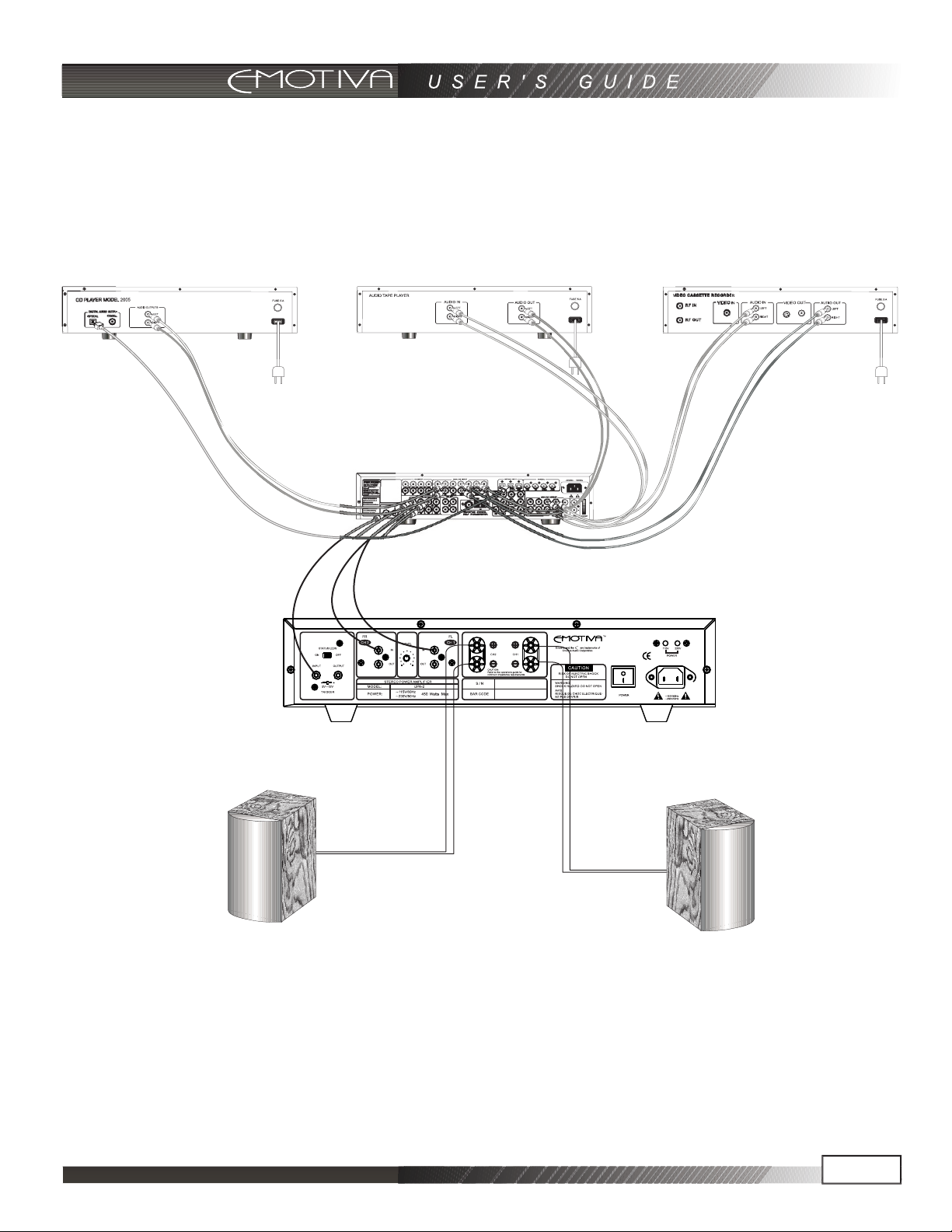
Connecting a 7.1 Preamp/Processor
Connection using a 7.1 channel preout to UPA-2
Emotiva LMC-2
VCR or DVRCD or DVD Player Cassette or DAT Player
Emotiva UPA-2
Page 13
Page 15
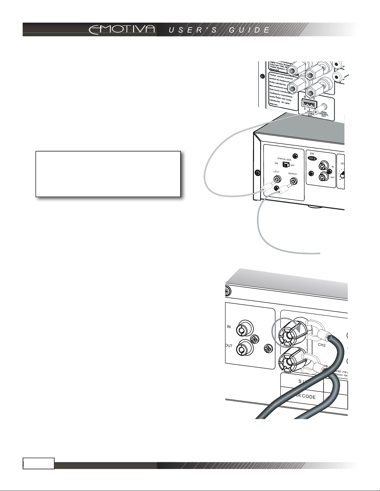
12V Trigger Connections
The 12 VDC trigger connection shown can be used to turn
the amplifier on when the preamplifier turns on. UPA-2 could
also be used to turn on another amplifier,when it is on.
This
trigger will actually trigger with any switched DC Voltage from
5-12 VDC (The trigger output voltage is 12VDC 500mA MAX);
however, the majority of home theater components use a
standard 12 VDC trigger connection for this function. This
is the preferred connection as it has the greatest degree of
reliability.
Never switch anything that plugs
directly into the wall with this trigger
connection. This action will damage
the unit and VOID THE WARRANTY.
Speaker Output Connections
The speaker output terminals for each amplifier
channel are located across the middle of the UPA-2.
The top post of each binding post pair is the positive
output, and connects to the positive (red) post of your
speaker. The bottom post of each pair is the negative,
and connects to the negative (black) post of your
speaker.
Regardless of the configuration used for the UPA2 amplifier channels, proper connection of each
speaker is essential. The 5-way binding posts
can accept bare wire, spade terminals, and dual
or single banana connectors. Spade connections
or banana plugs ensure a simple, solid fit in the
terminal whereas bare wire may be awkward when
the terminal is screwed down to compress the wire
into place. Keep in mind that if you use “dual banana” plugs and “stack” them, you will be creating a
parallel connection and this amplifier is not rated to play below 4 Ohms per channel.
Page 14
Page 16
Series and Parallel Speaker Connections
Whenever connecting more than one speaker per channel to an amplifier (regardless of the brand),
you must consider the way in which the amplifier will be impacted by adding the additional speaker(s).
Additionally, speakers with dual voice coils also apply to this consideration. Two voice coils in a single
speaker also cause different reactions from an amplifier depending on the way in which they connect
to the amplifier.
The connection of more than one speaker per channel will tend to degrade the speaker’s frequency
response and may make the amplifier run hot. For the best sonic results, use one speaker per
amplifier channel. If you must connect more than one speaker per channel, there are two methods in
which to do so: Series or Parallel.
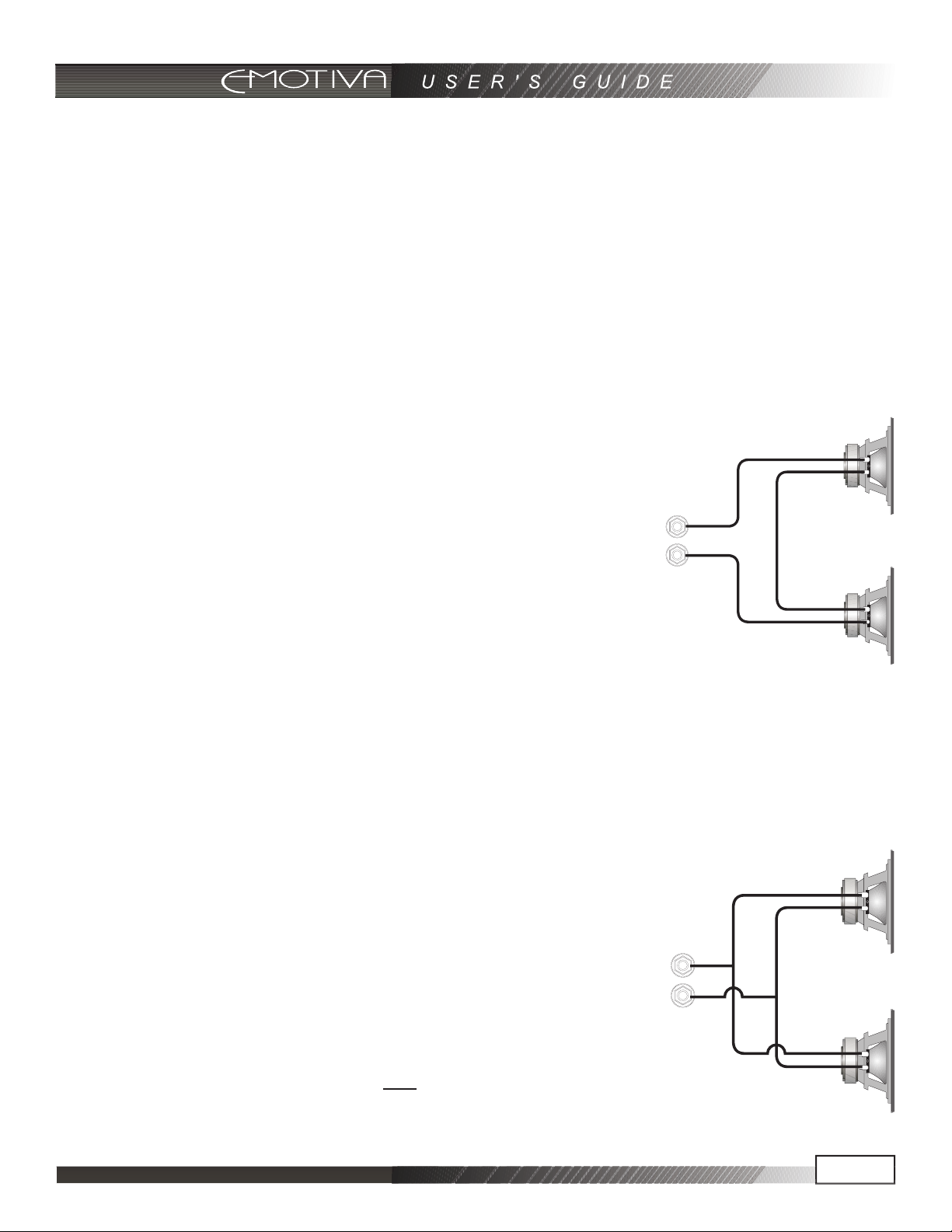
Series
A series connection is established when voice coils are connected in a
string – end to end – so there’s only one way for audio signals to flow
“in” and only one way for audio signals to flow “out”. For example, if you
were to series-connect two speakers to the front right channel of the
amplifier:
• The positive output terminal of the right channel connects to the
positive input post of the fi rst speaker.
• The negative input post of the fi rst speaker connects to the positive
input post of the second speaker.
• The negative input post of the second speaker connects to the
negative output terminal of the right channel.
An example of a SERIES
connection between two
speakers
The total impedance of speakers in series is found by adding their impedances together. For
example, two four ohm speakers in series is an eight ohm load. Series connections are easier on the
amplifier than parallel connections as the total impedance is higher than driving a single speaker.
Parallel
A parallel circuit is established when voice coils are connected in a way
that there are multiple paths for audio signals to flow “in” and multiple
paths for audio signals to flow “out”. When speakers are connected in
parallel, the total resistance at the amplifier is proportionally divided
based on the value of each individual voice coil resistance. The term
“divided” simply means all of the values together in parallel are a
SMALLER value than each all by itself. For example, if you were to
parallel connect two speakers to the front right channel of the amplifier:
• The positive output terminal of the right channel connects to the
positive input post of the fi rst speaker and to the positive post of the and to the positive post of the
second speaker.
An example of a PARALLEL
connection between two
speakers
Page 15
Page 17

• The negative output terminal of the right channel connects to the negative input post of the fi rst
speaker and to the negative post of the second speaker.and
The total impedance of equal speakers in parallel is found by dividing the impedance of one speaker
by the number of speakers. For example, two eight ohm speakers in parallel is a four ohm load (eight
ohms divided by two), four eight ohm speakers in parallel is a two ohm load (eight ohms divided by
four). Two ohm single channel loads are NOT RECOMMENDED for the UPA-2!
Running the UPA-2 below recommended impedance level can cause excessive heat and will
eventually drive the amplifier into protection
(blinking red LED’s on the front of the unit).
Parallel connections are harder on the amplifier than series connections, as the total impedance is
lower compared to driving a single speaker, and the amplifier must produce more current to drive
them.
Ideally, the total average impedance should be no less than 4 ohms per channel. You must make sure
that the lower impedance does not cause the amplifier to overheat, shut down, blow the line fuse, or
trip your circuit breaker. If this happens, you should reduce the number of speakers wired in parallel,
rewire them in series, or use more than one power amplifier.
Technical Note about Multiple Speaker Connections
Although there are two possible connection types discussed in this manual, it is imperative that with
either connection type that you use loudspeakers of the same type and nominal impedance for these
connections. In doing so, you have the most predictable outcome for your installation. When speakers
of different nominal impedances and/or different bandwidths are used, there are many other acoustic
problems that come into play in addition to complex impedance at the amplifier’s speaker output
terminals. If you must use multiple speakers on any individual amplifier channel, please use speakers
as close to identical as possible.
Page 16
Page 18

Troubleshooting Guide
The Emotiva UPA-2 is expertly designed and built to provide years of trouble-free performance. Most
problems that occur can usually be solved by checking your setup or making sure that the audio and
video components connected to the amplifier are on and fully operational.
The following information will help you deal with common setup problems you may experience during
normal use of your unit. If problems persist, contact Emotiva for help.
No Sound (from one or more speakers connected to the UPA-2)
• Speaker cables may have come undone. Turn off your system and check the cables, and tighten the ••
amplifi er and speaker binding posts.
• Damaged audio cable.
• The preamplifi er volume level is low for the channels concerned. Recheck the preamplifi er
calibration procedure.
• A preamplifi er Mute switch may be on, or an external processor loop or a tape monitor loop is
engaged.
• Check that your preamplifi er or source is running the correct surround sound mode. Maybe it is set
for 2-channel stereo when you were expecting 5.1 surround sound.
• Check in case any missing channels have been turned off in a preamplifi er setup menu. For
example, the center amplifi er channel will not receive a signal if the preamplifi er has been set to
“Phantom.”
• If the unit is not on, the ON/OFFswitch on the UPA-2 might be in the off position.
• A internal fuse on the unit may have blown. Contact Emotiva for assistance.
The amplifi er shuts down often or the line circuit breaker trips often
• Check that the positive and negative speaker wires are not shorted together.
• Make sure that no speakers are shorted internally. If you have an ohm-meter, disconnect the
speaker wires and measure the resistance between the speaker’s positive and negative terminals.
Measure all speakers and check their impedance speci
and Parallel Connections” section of this manual.
• If you have connected speakers in parallel, the overall impedance may be too low. It is
recommended that you rearrange the speakers in series to increase the overall impedance, thus
taking some of the load off the amplifi er.
• Make sure that the amplifi er has good ventilation and is not overheating. Allow good airfl ow
underneath wherever possible. If the amplifi er is in a closed rack, open up the rear panel or use a
quiet fan for improved ventilation.
Poor Bass Performance from Full Range Speakers connected to UP
• Make sure that your preamplifier does not have the bass (tone control) level turned down.
• Many surround preamplifi ers have controls which can direct all the bass to subwoofers, or let your
main speakers play the full range. Make sure that the preamplifi er has been correctly set. If you are
not using a subwoofer, set the speaker options to “Large” where possible.
fi cations. If necessary, review the “Series
A-2
Page 17
Page 19

• Check that the speaker wires have been connected correctly: Make sure that the positive of each
speaker connects to a positive output of the amplifi er, and the negative of each speaker connects
to a negative output. If one speaker is wired incorrectly, than it will be “out of phase” with the others,
resulting in poor bass performance. DOUBLE CHECK ALL THE SPEAKER CONNECTIONS!!
Turn-on and turn-off thumps
• Plug the amplifi er into an un-switched AC outlet, and use the 3.5mm Trigger Input connection
with a trigger between 5-12VDC from the source unit or preamplifi er (such as the Emotiva LMC-1
Preamplifi er/Processor). This should allow the amplifi er to turn on and off silently.
• If your powered subwoofer is the cause of the “thump” sound (not the other speakers connected to
U
PA-2), plug it into a different 115VAC outlet than the UPA-2 amplifi er so there is no power
surge
confl ict.
• Install a line conditioning device.
“Hum” Noises in the Speakers
This problem is more than likely caused by a “ground loop” in your system, rather than a fault in the
XPA-1. Follow these steps to isolate the main cause of the hum; there may even be more than one.
• Remember to turn off all components in your system, including the amplifi er, before disconnecting or
connecting any cables during troubleshooting.
• Try to have all of your equipment on the same electrical outlet or circuit. Group all the low power
components (preamp, CD player, DVD etc.) on a single outlet or power strip. This is provided that
the overall current draw from your equipment does not exceed the rating of the outlet or breaker.
• Disconnect all cables which come from outside the room, and check if the hum goes away. This
includes such connections as cable TV, satellite TV, or roof top antennas. Make sure that they are
disconnected where they fi rst enter the room, so they are making no connection to the preamplifi er
or the TV, or any other component. If the hum is caused by the cable TV line, then you will need
a “ground loop isolator.” This is an inexpensive device fi tted in line with the coaxial cable feed.
Contact your cable company or your Emotiva Dealer for assistance.
• Disconnect all connections from the preamplifi er to your TV, VCR or DVD.
• As a test, disconnect any other component which has a grounded power cord.
NOTE: Never remove the ground pin from any power cords (if present). This is very
dangerous.
• If the hum persists, disconnect all the source components one at a time from the back of the
preamplifi er, until you identify the problem.
• Try moving the speaker cables away from any power cords. Try just one speaker, connecting it to
each amplifi er channel and see if one channel is bad.
• Check that the interconnect cables to the amplifi er do not have any broken connections. The best
way to do this is to substitute a known good connection for the suspect connection. If you reverse
the cables and the problem goes away, the cable may be damaged or broken. This is possible even
if you can’t physically see the break as the strain for pulling on audio cables can sometimes break
the wire internally.
Page 18
Page 20

Ground loop isolators are available for audio lines and video devices. If you need assistance, contact
Emotiva
.
Although this is not always an ideal solution, the grounding di
fferences between
certain home entertainment components sometimes require ground loop isolators. This is the
exception rather than the rule.
Other Probable Causes of Noise
Speaker noise may also be caused by interference or noise on your AC line. Make sure there are no
large appliances sharing the line, or halogen lamps or light-dimming Triac devices.
• Try connecting your system to another AC socket on a separate line.
• If the hum is heard from within the UPA-2, and not through the speakers, this may also be caused by
interference on the AC or DC lines. The power transformers may turn this interference into an audible
noise. Internal hum can be made worse by a shelf or cabinet resonating, so try moving the UPA-2 to
another shelf.
• Try moving your components further away from the TV, especially if you ever notice the screen has
changed color in the area closest to the component.
• If you have very high effi ciency speakers, these may tend to reveal noises which other speakers do
not.
One or more RED lights on the Front Panel are Blinking
Each RED light indicates a fault condition for the corresponding power module. A fault condition is
one or more of the following:
• Excessive Operating Temperature
• Excessive Current (Short Circuit)
• DC on the Outputs
An excessive temperature fault can be reset by allowing amplifier to cool and cycling power on/off
button on the front panel. Excessive current (short circuit) can be reset by removing the cause of the
short f button on the front panel. DC at output is a possible fault condition thatand cycling power on/of
is if you have repeatedequipment related and requires technical assistance. Please contact Emotiva
problems causing the RED front panel light to flash that are NOT thermal or short circuit related.
Problems with the whole A/V System
If you are having more complex problems in your overall home entertainment system (not just with
the UPA-2 amplifie
, please contact Emotiva for UPA-2 professional installation assistance. These
r)
professio of home entertainment and lifestyle productsnals have years of experience with a wide range
and can offer you assistance in troubleshooting and rectifying problems.
Page 19
Page 21

UPA-2 Technical Specifi cations
Rated Power Output: (All Channels Driven @ 1Khz, 115VAC/ 60HZ supply, THD noted)
Channels 1-2 125 Watts into 8 Ohms (0.04%THD)
225 Watts into 4 Ohms (0.04%THD)
Frequency Response:
20-20Khz: +/-0.1dB
10-100Khz: +1/-3dB
Total Harmonic Distortion (THD): (80kHz measurement bandwidth)
Channels 1-2: <0.040%
Signal-to-Noise Ratio: >100dB, Unweighted (Full Output Reference)
DC Offset: <1mV
Crosstalk: >80dB
Damping Factor: Approximately 200 into 8 Ohms
Input Sensitivity Range (Gain):
Channels 1-2 31dB
Input Impedance (RCA Input): 23.5K Ohm
External Trigger Input: 5~12 VDC, center tip of 3.5mm jack is positive
External Trigger Output: 12VDC, 500mA max
Clearance for ventilation (Back): Minimum 2” / 50 mm
Electrical Power Requirement: 350 watts @ 115VAC when driven into 8 Ohms
Electrical Power Consumption: 4 Watts (Standby) and 30 Watts (Idle)
Raw Weight:
Shipping Weight: 39lbs /17.7kg
Dimensions: 17” W x 3.46” H x 16.7” D
432mm W x 88mm H x 423mm D
30lbs/ 13.6kg
Page 20 Page
Page 22

Limited Warranty
The Emotiva UPA-2 has been created to perform flawlessly for many years. As a result of this quality
and craftsmanship, Emotiva offers the following warranty to owners of the UPA-2.
Emotiva Audio warrants the UPA-2 to be free from defects in materials and workmanship for a period
of fi ve years from the original date of purchase. The following items are excluded from, or will void
this warranty coverage:
1) Damage to the UPA-2 caused during shipment and handling.
2) Damage to the UPA-2 caused by accident, misuse or abusive operation contrary to the instructions
specifi ed within this manual.
3) UPA-2 units that have had the serial numbers defaced, modifi ed, or removed.
4) Damage to the UPA-2 resulting from a modifi cation of, or attempted repair by any person or
company not authorized by Emotiva.
5) Any UPA-2 unit purchased from a non-authorized dealer.
6) Emotiva does not assume liability for loss of use, or damage to, associated or connected
equipment.
7) Emotiva also does not assume liability for the shipping charges incured to or from
Emotiva Audio Corp. All shipping charges are the sole responsiability of the user.
8) Emotiva Audio Corp. does not assume the responsiability to provide a replacement
unit during times of service.
Service Assistance for the UPA-2
Please note that BEFORE sending your UPA-2 in for repair, you MUST call Emotiva and obtain a
return authorization (R/A) number. Before contacting Emotiva to begin the R/A process, please have
as detailed a description of the problem(s) you are experiencing and the conditions under which the
problem(s) occur. Additionally, please be sure to check the troubleshooting guide in this manual to
rule out the possibility of something simple you may have overlooked. Please remember, this is a
complicated product and most instances of perceived product failure are the result of improper set
up or operation. Emotiva and its dealers will help you ascertain whether you have an operational
problem or product defect.
Once you have obtained the R/A number, you must print this clearly on the outside of the box so it will
be possible to determine from whom the UPA-2 came once it arrives. Parcels arriving without an
number will be refused and returned freight collect.
R/A
If you purchased your unit directly from
Emotiva or from an authorized Emotiva
Dealer, please send your repairs with R/A
number to:
Emotiva Audio Corp.
Attn.: Repair Department
106 Mission Court, Suite 101
Emotiva Disclosure
Franklin, TN 37067
Reference - (Put your R/A number in this spot)
Copyright 2008 Emotiva
All Rights Reserved. Emotiva reserves the right to make improvements to its products at any time.
Therefore, the specifications of the product and the specific details of this manual are subject to
change at any time.
Page 21
Page 23

Rev 1.06 12/2008
Emotiva Audio Corp.
106 Mission Court, Suite 101
Franklin, TN 37067
Toll Free - (877) EMO-TECH
Website - www.emotiva.com
 Loading...