

Page 1
Documentation Version 1.2.6Documentation Version 1.2.6
USER’S GUIDE
Documentation version 1.2.6
Page 2

2
INTRODUCTION
Documentation Version 1.2.6
INTRODUCTION
Page 3
Documentation Version 1.2.6Documentation Version 1.2.6
/ 3
INTRODUCTION
INTRODUCTION
• Objective:
Provide a visual guide of the dierent steps to set-up and get
started using the MicroDelta Rework 3D printer.
• Authors of this document :
eMotion Tech – http://www.emotion-tech.com
Hugo FLYE
Anthony BERNA
• Photographics credits :
Pictures and 3D representations made by eMotion Tech :
http://www.emotion-tech.com
• Sources :
http://reprap.org/wiki/RepRap
http://www.repetier.com/
• Licence :
MicroDelta Rework : CC BY-NC-SA 4.0
is document : CC BY-NC-SA 4.0
http://creativecommons.org/licenses/by-nc-sa/4.0/
• Update:
Last update : 09/10/2017
• Links :
You can nd more informations on the following links :
eMotion Tech’s website : http://www.emotion-tech.com
RepRap community : http://reprap.org/wiki/reprap
RepRap
Page 4

4
INTRODUCTION
Documentation Version 1.2.6
SUMMARY
INTRODUCTION 2
SUMMARY 4
SOFTWARE INSTALLATION 5
A. Software installation on Mac OS 6
PREPARATION 7
A. Files to copy on the TF card 8
B. Connecting your printer to Repetier-Host 9
C. Printer’s settings 11
D. Slicing settings 13
E. Motion test 15
F. Heating test 16
G. Charging lament 17
H. Extrusion test 18
I. Calibration process using command lines 19
PRINTING 22
A. Spool Holder Print 23
APPENDIX 27
Mounting of the spool holder 28
Spring lament pressure adjustment 30
Printing a 3D model 33
PID calculation 36
To go further 37
Maintenance 38
Recommandations 38
Restore the TF card 39
Page 5

Documentation Version 1.2.6Documentation Version 1.2.6
/ 5
SOFTWARE INSTALLATION
SOFTWARE
INSTALLATION
Page 6

6
SOFTWARE INSTALLATION
Documentation Version 1.2.6
Soware installation on Mac OS
Objective : Install the necessary soware to use the MicroDelta Rework on a Mac operating system computer.
1°) Dowload the latest version of Repetier-Host from the support section of eMotion Tech’s website (www.emotion-tech.com).
Support / MicroDelta Rework / Soware / Mac /
2°) Find all the necessary informations for the installation on the following link :
https://www.repetier.com/documentation/repetier-host-mac/installation-and-connection/
Note: the version of Repetier for Mac OS X is less developed than those on Windows / Linux. erefore the use of a virtual machine is advised to take
advantage of the latest updates and added options. However, we will guide you through this documentation for the installation of the ocial version
of Repetier for Mac OS X.
Page 7

Documentation Version 1.2.6Documentation Version 1.2.6
/ 7
PREPARATION
PREPARATION
Page 8
8
PREPARATION
Documentation Version 1.2.6
Files to copy on the TF card
1°) Go to the eMotion Tech’s website support section, then go to «MicroDelta Rework / Soware / Conguration» and download the corresponding conguration les to your MicroDelta Rework depending on it’s version and options.
2°) Connect your printer to the computer
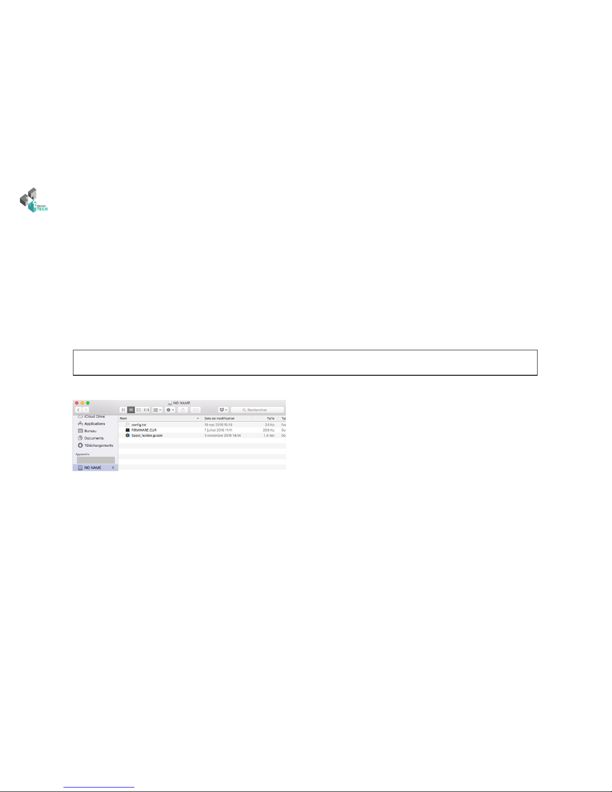
3°) Once downloaded, unzip the le and copy all its content in the eMotronic’s TF card.
Objective : copy the required les in the eMotronic’s TF card.
Note: TF card is usually automatically detected and its content displayed once you connect your 3D printer to you computer. e
TF card generally appears as drive «NO NAME» but this can vary depending on your hardware.
4°) Press the «Reset» button on the 3D printer (located on one side of the lower plate).
Mac OS X : what you should have on the TF card aer this step
5°) Check that the device has been properly recognized by your operation system.
Page 9
Documentation Version 1.2.6Documentation Version 1.2.6
/ 9
PREPARATION
Connecting your printer to Repetier-Host
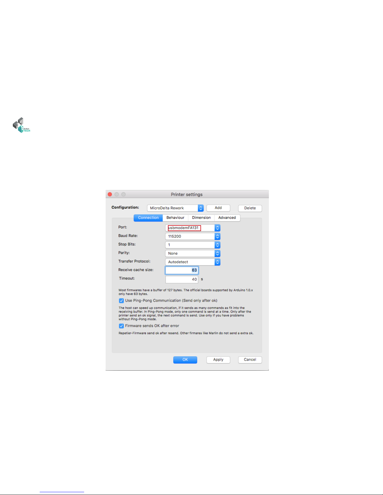
1°) Run Repetier-Host soware.
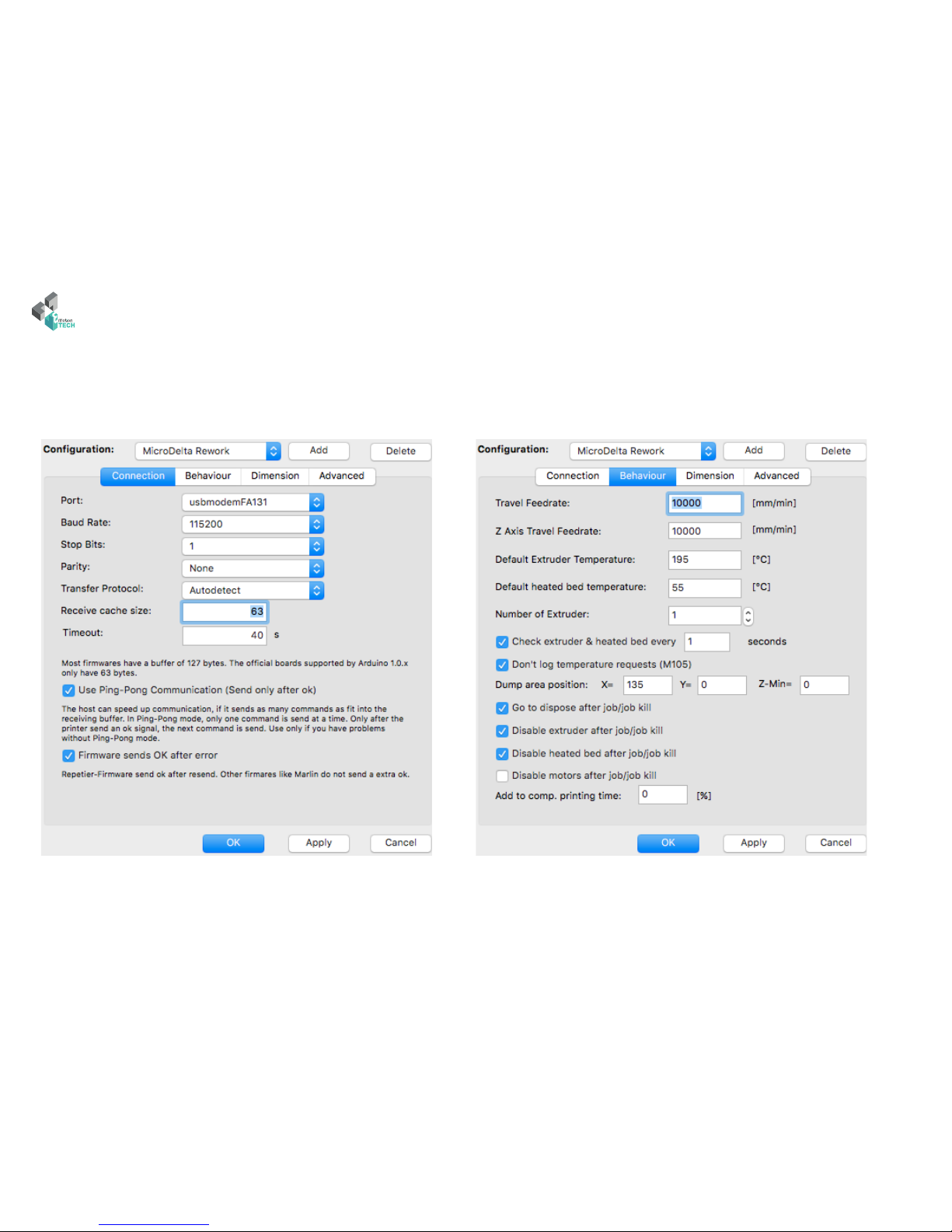
2°) Go to «Cong» then «Printer Settings».
3°) Check that all the parameters correspond to those on the image below. Select the COM port assigned to your MicroDelta Rework.
Page 10
10
PREPARATION
Documentation Version 1.2.6
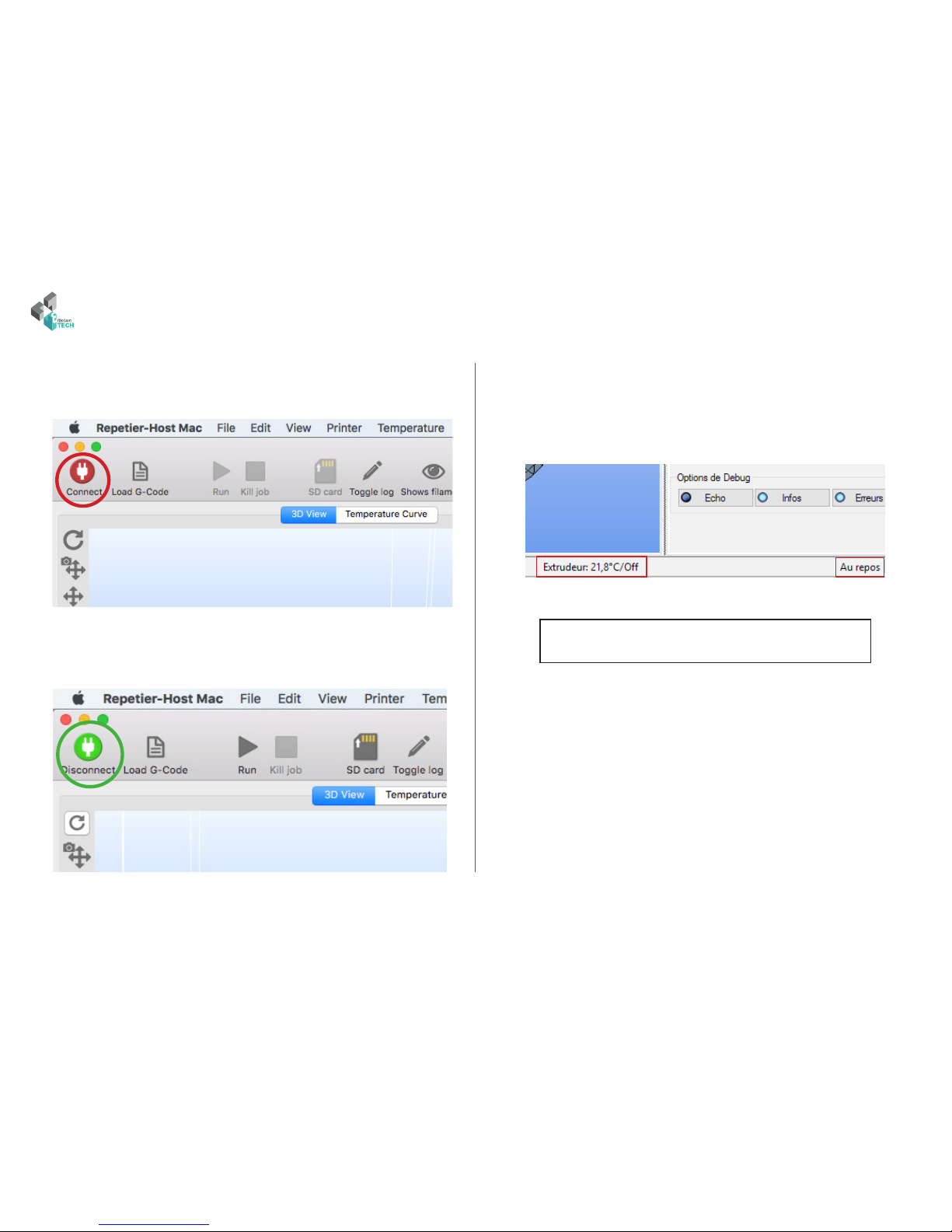
4°) Click on Connect.
is one should change color, becomes green when connected :
5°) Check on the bottom of the screen that the extruder’s temperature
is consistent (logical value) and the printer’s status is «Idle» as shown
below:
If you have a Heated Bed, its temperature will be displayed
next to the extruder’s.
Page 11
Documentation Version 1.2.6Documentation Version 1.2.6
/ 11
PREPARATION
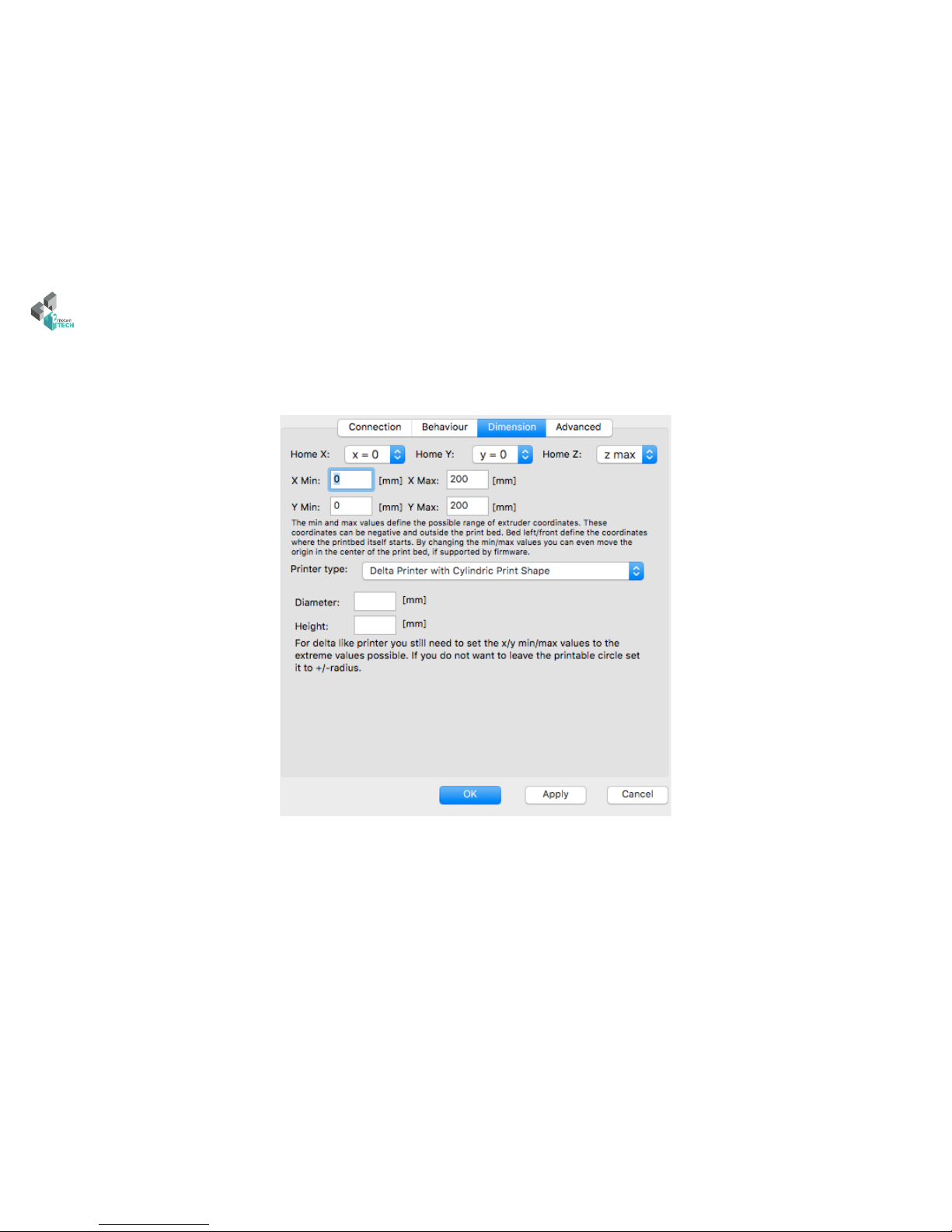
Printer’s Settings
A manual set-up of the printer is required. Please follow the following steps:
Page 12
12
PREPARATION
Documentation Version 1.2.6
220
150
Page 13
Documentation Version 1.2.6Documentation Version 1.2.6
/ 13
PREPARATION
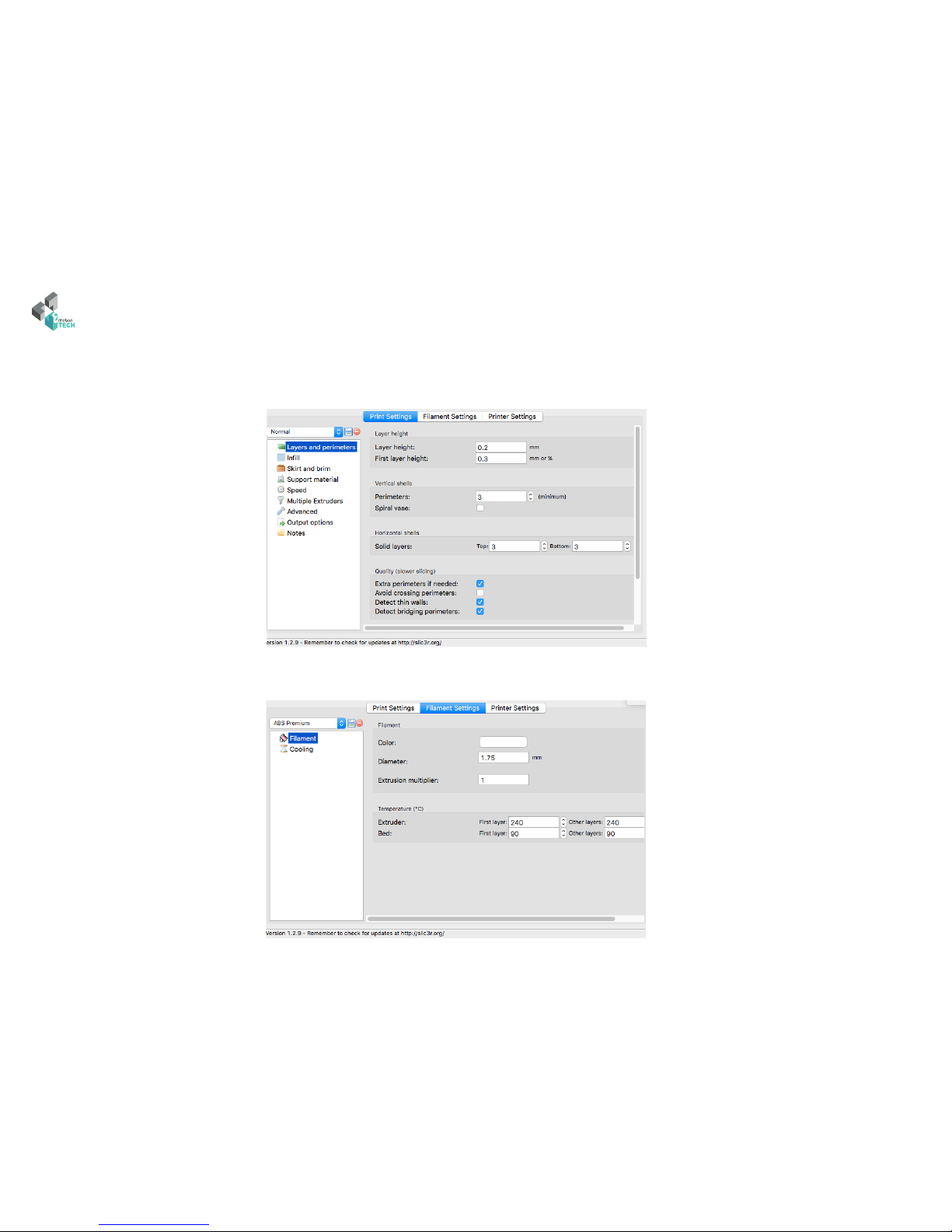
Slicing Settings
Go to the slicer tab, and click on the «Conguration» button.
Make sure to modify you Slic3r conguration values in respect with the following gures.
Save
Page 14

14
PREPARATION
Documentation Version 1.2.6
Save
Save
Page 15

Documentation Version 1.2.6Documentation Version 1.2.6
/ 15
PREPARATION
Motion test
1°) Go to the «Print Panel» tab and click on the «Home All» (is should
initialize your printer = move all axes to origin).
2°) Make sure that EVERY slider moves up till hitting its coresponding endstop.
Keep a nger on the «Reset» button in case of a malfunction.
Page 16

16
PREPARATION
Documentation Version 1.2.6
Heating Test
1°) Go to «Print Panel» tab, click on «Heat on» (Extruder heater activation) as shown below:
2°) Check that the target temperature is reached :
195
If the target temperature is not reached or the actual temperature varies
greatly around the target temperature, perform a PID calculation (see
appendix).
Page 17

Documentation Version 1.2.6Documentation Version 1.2.6
/ 17
PREPARATION
Charging lament
2°) Disengage the extruder
Disengage by pushing
here
3°) Insert the lament in the extruder’s inlet and
push it as far as possible
inlet
4°) If you encounter a hard point while inserting the lament,
engage the extruder and turn the drive wheel until the lament
gets to the nozzle, melted lament should start coming out
Drive
wheel
Filament tip
Filament
1°) Cut the tip of the lament with a certain angle
to make its insertion in the extruder easier
5°) Tighten the spring strongly by turning the knurled screw.
Note: if the knurled screw is not tight enough, the lament will be badly driven
Knurled screw
Page 18

18
PREPARATION
Documentation Version 1.2.6
Extrusion test
1°) In the «Print panel» tab, perform a extrusion of 50mm.
If this is not the case, adjust accordingly the tension exerted on the lament
from extruder, and this by turning the Knurled Screw of the extruder.
2°) Verify that melted lament comes out of the nozzle regularly.
195
195
50
Page 19

Documentation Version 1.2.6Documentation Version 1.2.6
/ 19
PREPARATION
Calibration process using command lines
On mac OS computers the calibration processs must be done using Gcode commands, here’s how to do this:
1°) Make sure the printhead is at room temperature.
2°) Mount the calibration module on the printer’s core and plug the jack
connector on the eMotronic board
4°) Start the calibration using G32 command, it wil probe 3 points of the bed.
3°) Go to «Print Panel» tab. Home or initialize your printer using the G28
command.
G28
G32
Page 20

20
PREPARATION
Documentation Version 1.2.6
5°) When done, start the full bed calibration using G31 command, this
will probe multiple points of the bed to optimize the rst calibration. is
is known as grid compensation strategy.
6°) When done, save the grid values using M374 command.
7°) Remove and unplug the calibration module.
Maximum Z height
8°) Home or initialize your printer
G31
M374
Homing
Page 21

Documentation Version 1.2.6Documentation Version 1.2.6
/ 21
PREPARATION
10°) Move the printhead down using the commands shown below in the manual control tab.
Once the printhead is close enough from the paper, move the printhead down
slowly by jogging down of 0,1mm at a time, repeat until the printhead touches
the paper and holds it from moving.
M500
9°) Place a paper on the bed
11°) Set the maximum Z height using the M306 Z0 command
12°) Save using M500
e calibration process is meant to be done once and not
before every print. In some cases, the calibration could
become unaccurate, aer disassembling and reassembling
structural parts of you printer per example, you should
then calibrate again your printer.
Calibration may not be performed correctly. Usually, this
comes from the fact that it resides some mechanicals plays
on the machine. In this case, it will then be necessary to
review the mounting of the printer so as to ensure that eve-
rything is tight and without play (smooth rods, ball joints,
belts, pulleys, etc.).
In case of troubles during the calibration process :
Page 22

22
PREPARATION
Documentation Version 1.2.6
Objective : rene the height adjustment of the nozzle relative to the heatbed.
Description : if the material hangs too much or not hangs well enough to the 3dBedFix coating, you may need to adjust the nozzle height.
In the case the material doesn’t hang well to the coating, please send the following GCODE command lines in the dedicated input eld of the «Manual
Control» tab :
G1 Z0
M306 Z0.1
M500
In the case where the material hangs too much to the coating and is dicult to unhook :
G1 Z0.1
M306 Z0
M500
In both cases, the value «0.1» can be changed as necessary.
You will then be able to launch an impression and check the following points of details :
- material that does not hangs well to the 3dBedFix = nozzle too far from the 3dBedFix (adjust height)
- material that hangs too much on the 3dBedFix = nozzle too close to the coating (adjust height)
Precise adjustment of the maximum height
Input eld for sending GCODE command
Send
Page 23

Documentation Version 1.2.6Documentation Version 1.2.6
/ 23
PRINTING
PRINTING
Page 24

24
PRINTING
Documentation Version 1.2.6
Spool Holder print
1°) Load the Gcode called «spool_holder.gcode» from the TF card.
You are about to start your rst print.
You will be print the spool holder, which will be mounted on the top plate of the MicroDelta Rework.
Page 25

Documentation Version 1.2.6Documentation Version 1.2.6
/ 25
PRINTING
2°) Click on «Run» to start the print.
Print will begin, your printer will initialize (homing) and start heating the extruder and eventualy the Heat bed.
Page 26

26
PRINTING
Documentation Version 1.2.6
CONGRATULATIONS !
You successfully printed your rst
object !
Go to the «Appendix» to nd explanations about mounting the
spool holder.
Page 27

Documentation Version 1.2.6Documentation Version 1.2.6
/ 27
Appendix
Appendix
Page 28

28
Appendix
Documentation Version 1.2.6
M3x8mm screw
Objective : mount the spool holder on the top plate
Thrust bearing
Printed spool holder part
Mounting of the spool holder
Page 29

Documentation Version 1.2.6Documentation Version 1.2.6
/ 29
Appendix
Result
Page 30

30
Appendix
Documentation Version 1.2.6
1°) Relieve the spring pressure completely by unscrewing the horizontal knurled screw of the eMostruder
2°) In the Repetier-Host soware, with the 3D printer connected and turned on, from the «Manual control» tab, ask for a target temperature dedi-
cated to the used lament and wait until it is reached.
3°) If some lament is already engaged in the machine, remove it and cut it o to an healthy base not marked by the driving wheel.
(with the end of the new lament bevelled in the winding direction of the spool or sample provided)
Spring lament pressure adjustment (eMostruder)
Objective : adjust the pressure exerted by the spring on the lament so that the drive is optimal and does not cause abnormalities.
Description : depending on the type of lament used (PLA, G-FIL, ABS, etc.) and especially its hardness, it will be necessary to adjust the spring
pressure so that the driving wheel does not mark the lament too much and does not block in its passage to the nozzle. is method ensures that
the lament drive is operational while exerting pressure on the lament as low as possible.
195
Page 31

Documentation Version 1.2.6Documentation Version 1.2.6
/ 31
Appendix
4°) Engage the new unmarked lament to the nozzle.
5°) Always in the «Manual Control» tab of Repetier-Host, ask for one or more slow extrusions of 100 mm.
6°) At the same time, observe the lament coming out of the nozzle and check that the extrusion is continuous and homogeneous at a speed corresponding to
the speed of the driving wheel.
Click the button to extrude
100
Page 32

32
Appendix
Documentation Version 1.2.6
7°) If the lament does not come out of the nozzle: tighten the screw a little more until it is homogeneous.
Page 33

Documentation Version 1.2.6Documentation Version 1.2.6
/ 33
Appendix
Printing a 3D model
2°) Import your model on Repetier-Host :
• In the «Object placement» tab, click on «Add STL le»
• Select your desired 3D model le and open
1°) Download a 3D part, we suggest you the eMotion Tech’s keyring :
https://data.emotion-tech.com/p/Ressources_3D_eMotion_Tech/Porte_clef_eMotion-Tech.stl
Virtual representation
of the objet on the print
surface
List of the objects your added
Prerequisite : Fully calibrated 3D printer
Page 34

34
Appendix
Documentation Version 1.2.6
2°) You can edit your object with many options :
3°) Slice your object with the pre-congured Slic3r prole :
• In the «Slicer» tab, select «Slice with Slic3r».
When done click on «Slice with CuraEngine»
Page 35

Documentation Version 1.2.6Documentation Version 1.2.6
/ 35
Appendix
4°) When slicing is done, a virtualization of the printed object is generated, only one thing le is to click on «Print» button.
Page 36

36
Appendix
Documentation Version 1.2.6
To go further
On regular basis updates for your MicroDelta Rework are uploaded on our website. You can nd them in the «Support» section of
the site, under «MicroDelta Rework / improvements.»
Do not hesitate to regularly check that folder to keep your printer up-to-date.
PID calculation
By GCODE commands :
1°) Make sure the print head temperature is at room temperature.
2°) Disable the secondary fans.
3°) In the «Manual control» tab, use the input eld for sending GCODE commands :
Send the following command : M303 E0 S250 C8
Details :
• E0 = extruder number 1
• S250 = target temperature at 250°C
• C8 = 8 cycles of regulations around the target temperature
Once the command is sent, Repetier-Host logs will show you the progress of the calculation.
When the calculation is nished, the new values P, I and D are indicated in the logs.
4°) Send the following GCODE command to save : M500
If you have the LCD screen :
In the menu of the screen is integrated an option to directly calculate the PID.
Just go to the «Calibrate / PID hotend» menu.
Preamble : e PID values are necessary for the temperature control of the heating elements. If you nd that the target temperature is
di cult to reach or the actual temperature varies a lot around the target temperature, it may be useful to recalculate the PID values.
Page 37

Documentation Version 1.2.6Documentation Version 1.2.6
/ 37
Appendix
PID calculation
By GCODE commands :
1°) Make sure the print head temperature is at room temperature.
2°) Disable the secondary fans.
3°) In the «Manual control» tab, use the input eld for sending GCODE commands :
Send the following command : M303 E0 S250 C8
Details :
• E0 = extruder number 1
• S250 = target temperature at 250°C
• C8 = 8 cycles of regulations around the target temperature
Once the command is sent, Repetier-Host logs will show you the progress of the calculation.
When the calculation is nished, the new values P, I and D are indicated in the logs.
4°) Send the following GCODE command to save : M500
If you have the LCD screen :
In the menu of the screen is integrated an option to directly calculate the PID.
Just go to the «Calibrate / PID hotend» menu.
Preamble : e PID values are necessary for the temperature control of the heating elements. If you nd that the target temperature is
di cult to reach or the actual temperature varies a lot around the target temperature, it may be useful to recalculate the PID values.
Page 38

38
Appendix
Documentation Version 1.2.6
Maintenance
A monthly maintenance of the 3D printer is recommended.
Below are some recommendations:
Using a brush, dedust the following:
• Emotronic board
• All the fans to ensure a good airow
• Cold part of the printhead
- To clean the printhead follow the guide dedicated to the Hexagon hotend on the following link:
http://data.emotion-tech.com/highlights_fr/Hexagon%20-%20Notice%20montage-debouchage.pdf
- Clean the teeth of the drive wheel using a sharp ended tool like a needle tip, the end of tweezers or a cutter blade.
- Check & tighten the screws of the 3D printer.
- Lubricate the various mechanical transmission elements with multipurpose grease.
Recommandations
Turning o your 3D printer :
After printing, if you want to turn o the machine, wait until the print head cools down to room temperature to
ensure that the print head doesnt get clugged.
Transport :
If the printer has to be transported by car or another mean of transport in which it could be subject to vibration, it is
recommended to unplug all the motors from the eMotronic board to avoid damaging it.
Troubleshooting :
A FAQ on the MicroDelta Rework is available on our website in the «Support» section, please refer to it
to troubleshoot your printer, most problems could be solved through this tool !
Page 39

Documentation Version 1.2.6Documentation Version 1.2.6
/ 39
Appendix
Restore the TF card
1°) Remove the TF card by pressing it, you will hear a click indicating that the card is no longer locked and can be removed without damage to
the reader.
Objective : prepare the les of the TF card again in order to eliminate the corrupted les and defective cells.
Description : for various reasons, the les present in the TF card and / or the cells of this card can be damaged. You will nd through this proce-
dure how to restore the TF card and the necessary les to MicroDelta Rework.
Press to eject and pull
2°) en read this TF card with an external drive on your computer (very useful because the formatting is too long by USB cable).
3°) Perform a formatting of the TF card in MS-DOS FAT format using the tool named «Disk Utility».
Select the Micro TF card
Make sure that options are
congured as shown
Click the «Erase» button
Click on «Erase»
Page 40

40
Appendix
Documentation Version 1.2.6
4°) Download the latest rmware on our website «reprap-3d-printer.com» in the support section, in the tree dedicated to your machine.
Firmware for heating bed with or without LCD
Firmware without heating bed with or without LCD
5°) Go inside the rmware folder, select all the les and nally copy them to the root of the TF card.
6°) Eject the TF card (right click on the TF card then «Eject»).
7°) Disconnect the Micro TF card reader from the computer.
Click here
Page 41

Documentation Version 1.2.6Documentation Version 1.2.6
/ 41
Appendix
9°) Insert the TF card into the eMotronic drive.
Press to the click
(the card is locked)
10°) Press the «Reset» button located on the lower metal part to take into account the new rmware.
11°) In the TF card, make sure that the «rmware.bin» le is changed to «rmware.cur».
12°) On the eMotronic board, between the USB connector and the auto-leveling sensor connector, make sure that:
- LED1 remains on
- LED2 and LED3 ash continuously
- LED4 remains on
LED1
LED2
LED3
LED4
LEDs
From there, the eMotronic card should be recognized by the Device Manager and the contents of the TF card should be displayed in the Files Explorer. It will then only remain to realize again the calibration of the 3D printer.
Page 42

42
Appendix
Documentation Version 1.2.6
Thank you for choosing us!
www.emotion-tech.com
 Loading...