

Page 1
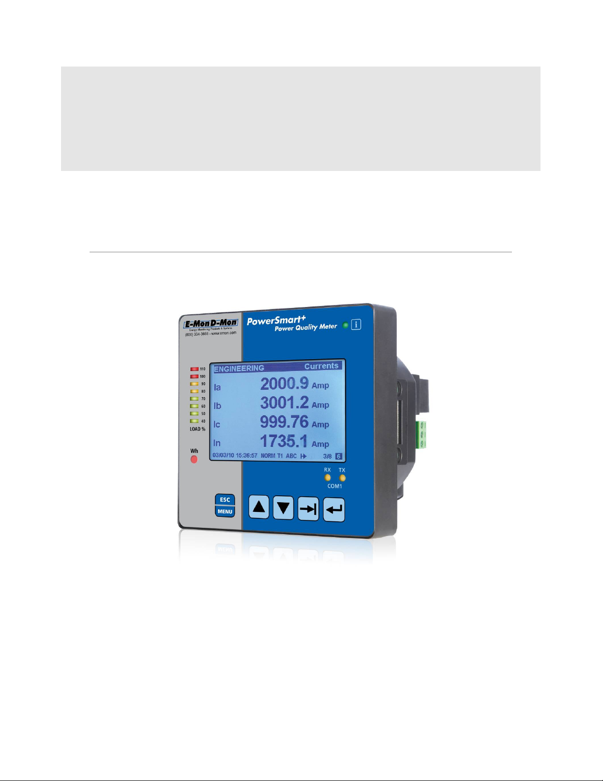
PowerSmart+
Power Quality Meter
Installation and Operation Manual
BG0543 Rev. A1
Page 2
LIMITED WARRANTY
The manufacturer offers the customer a 24-month functional warranty on the
instrument for faulty workmanship or parts from date of dispatch from the
distributor. In all cases, this warranty is valid for 36 months from the date of
production. This warranty is on a return to factory basis.
The manufacturer does not accept liability for any damage caused by instrument
malfunction. The manufacturer accepts no responsibility for the suitability of the
instrument to the application for which it was purchased.
Failure to install, set up or operate the instrument according to the instructions
herein will void the warranty.
Only a duly authorized representative of the manufacturer may open your
instrument. The unit should only be opened in a fully anti-static environment.
Failure to do so may damage the electronic components and will void the warranty.
The greatest care has been taken to manufacture and calibrate your instrument.
However, these instructions do not cover all possible contingencies that may arise
during installation, operation or maintenance, and all details and variations of this
equipment are not covered by these instructions.
For additional information regarding installation, operation or maintenance of this
instrument, contact the manufacturer or your local representative or distributor.
WARNING
Read the instructions in this manual before performing installation and take
note of the following precautions:
Ensure that all incoming AC power and other power sources are
turned OFF before performing any work on the instrument. Protect
the measurement AC Inputs voltage (V1, V2, V3) with 2A external
overcurrent protection device and the power supply source inputs
with 5A external overcurrent protection device, located close to the
equipment.
Before connecting the instrument to the power source, check the
labels on the back of the instrument to ensure that your instrument
is equipped with the appropriate power supply voltage, input
voltages and currents. Failure to do so may result in serious or even
fatal injury and/or equipment damage.
Under no c ircu mstanc es should the instrum ent be connected to
a power source if it is damaged.
To prevent potential fire or shock hazard, do not expose the
instrument to rain or moisture.
The secondary of an external current transformer must never be
allowed to be open circuit when the primary is energized. An open
circuit can cause high voltages, possibly resulting in equipment
damage, fire and even serious or fatal injury. Ensure that the current
transformer wiring is secured using an external strain relief to
reduce mechanical strain on the screw terminals, if necessary.
Only qualified personnel familiar with the instrument and its
associated electrical equipment must perform setup procedures.
Do not open the instrument under any circumstances when it is
connected to a pow er source.
2 PowerSmart+ Power Quality Meter
Page 3
Do not use the instrument for primary protection functions where
failure of the device can cause fire, injury or death. The instrument
can only be used for secondary protection if needed.
Read this manual thoroughly before connecting the device to the
current carrying circuits. During operation of the device, hazardous
voltages are present on input terminals. Failure to observe
precautions can result in serious or even fatal injury or damage to
equipment.
⇒⇒⇒⇒
This equipment does not require cleaning for proper operation
All trademarks are property of their respective owners.
Copyright 2013
PowerSmart+ Power Quality Meter 3
Page 4
Quick Start Guide
This section can be used by a licensed electrician to install and perform basic
POWERSMART+ PQM setup. For more detailed POWERSMART+ PQM setup
and use instructions, see the following chapters in this manual.
This quick start guide will assist you to have the unit running for the first
time.
During the operation of the meter, hazardous voltages are present in
the input terminals. Failure to observe precautions can result in
serious or even fatal injury or damage to equipment.
For complete and accurate in-depth instructions, refer to the following
chapters in this manual.
1. Installing the PowerSmart+ PQM
Mounting the PowerSmart + PQM Unit
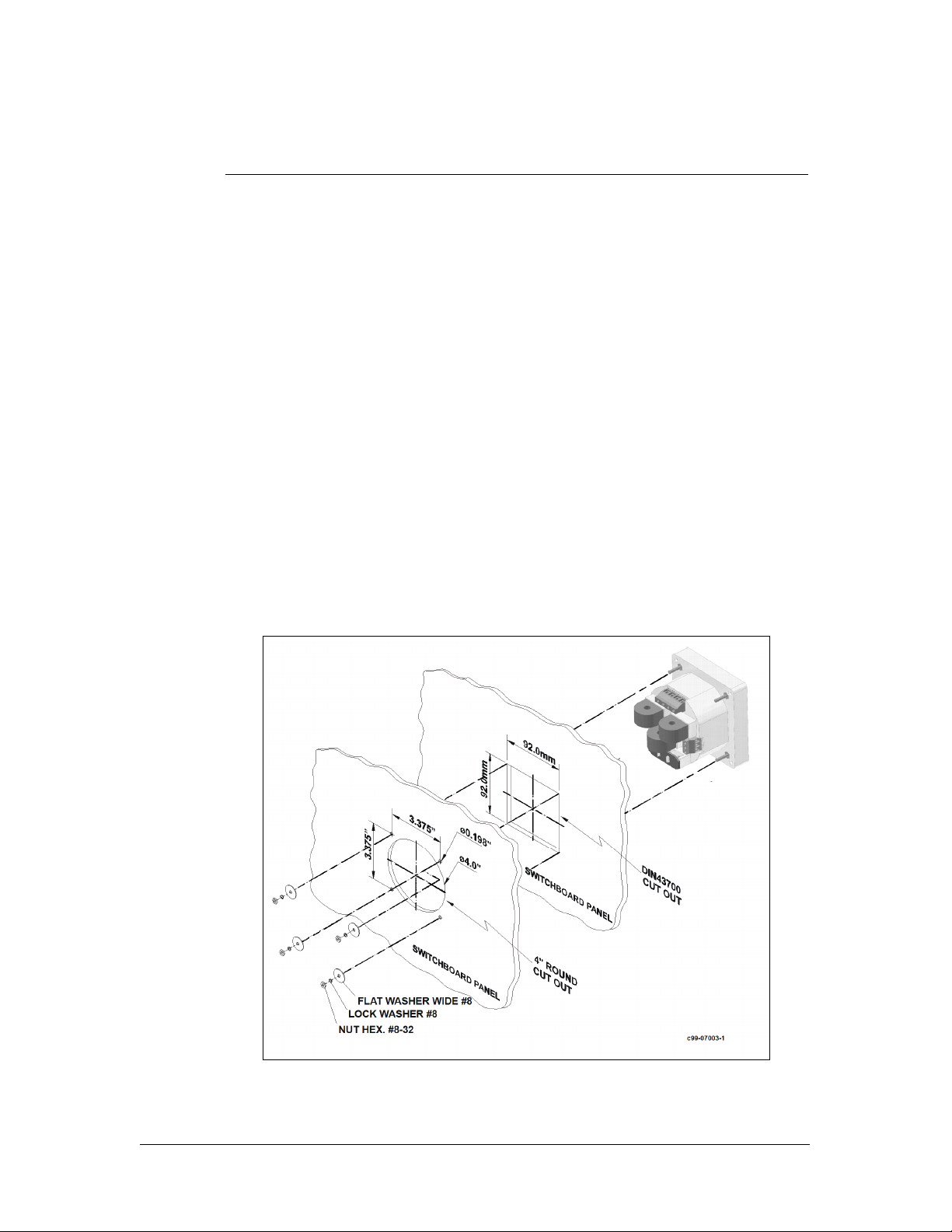
To mount the PowerSmart + PQM:
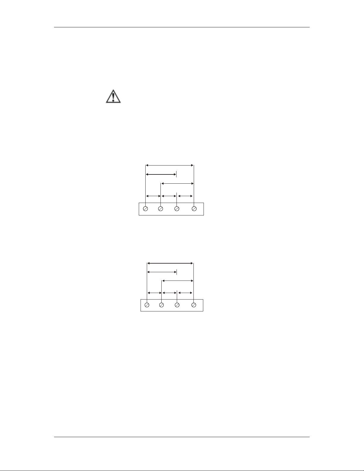
1. Position the PowerSmart+ PQM unit in the square or
round cutout. If two PowerSmart+ PQM are
positioned side by side, take care of proper interval
between them.
2. Attach the PowerSmart+ PQM unit using washers
and nuts. Make sure that the unit is securely
attached into the wall or cabinet fixture.
Mounting the PowerSmart+ PQM (Square or Round Cut-out)
4 PowerSmart+ Power Quality Meter
Page 5
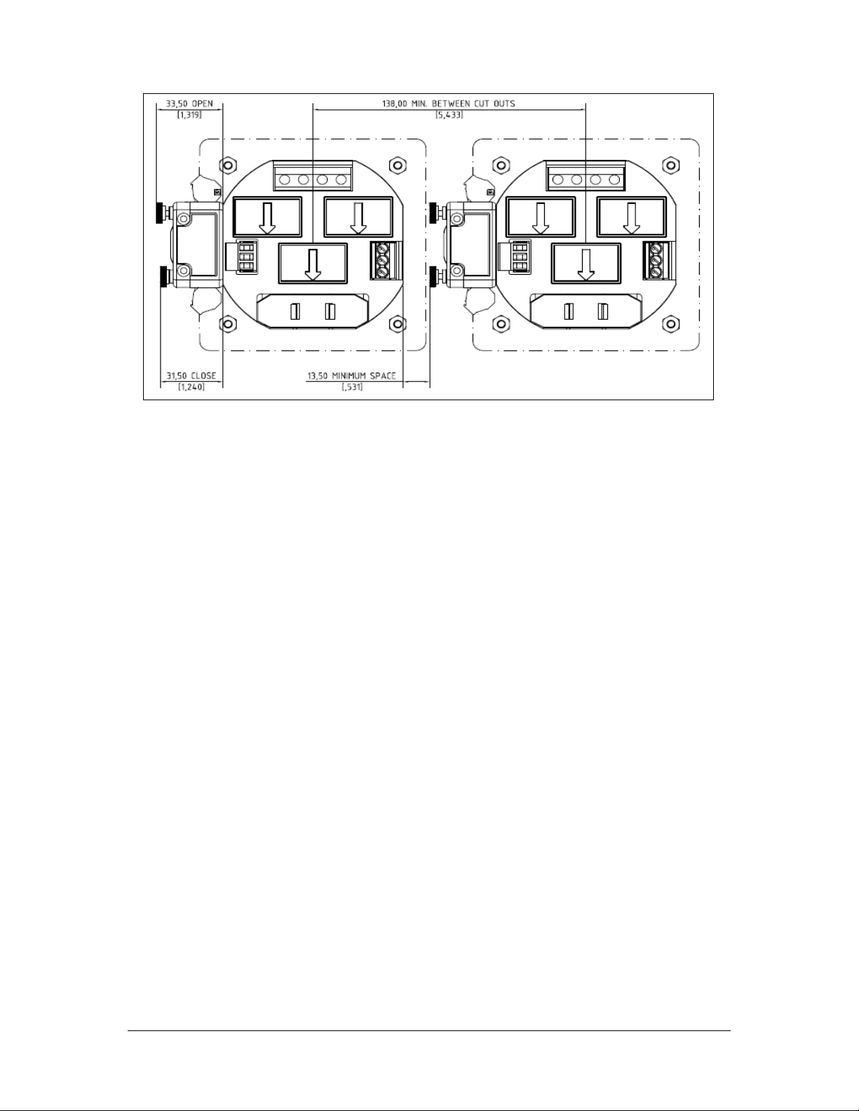
Mounting two PowerSmart+ PQM side by side
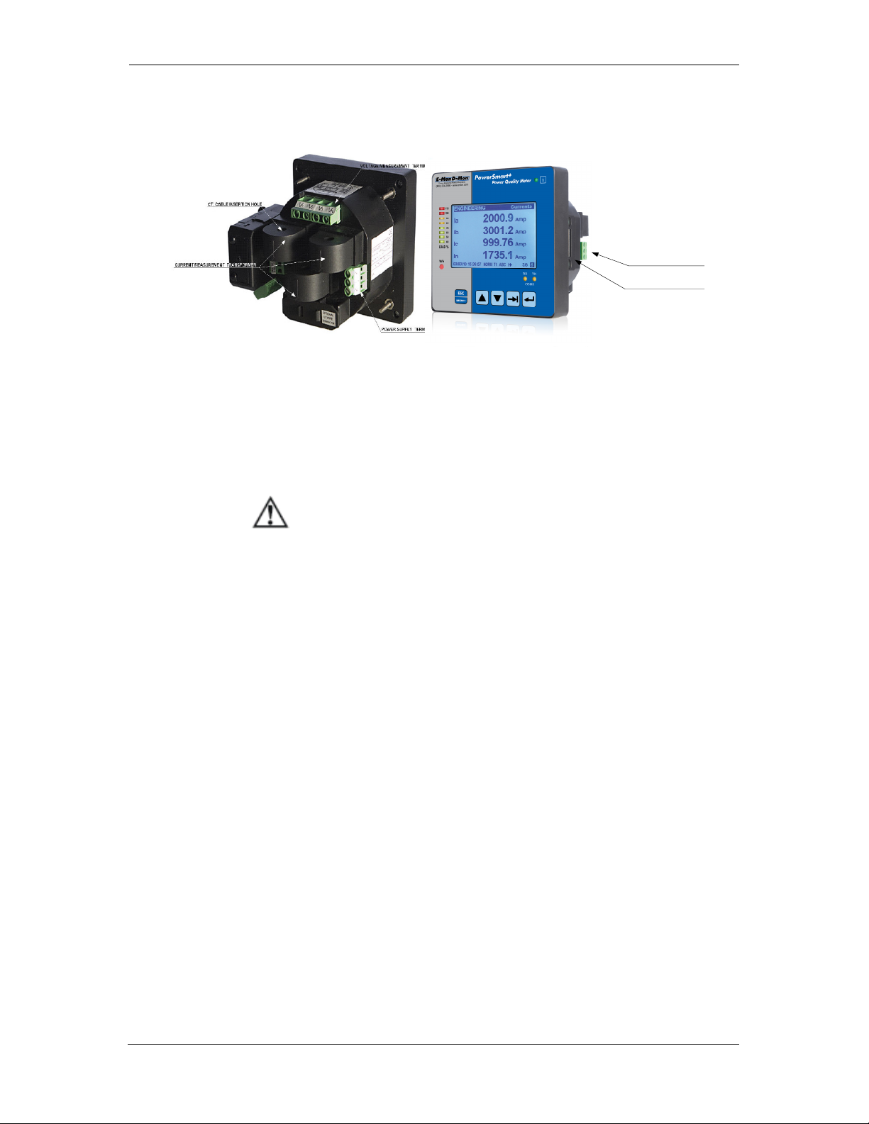
Connecting the PowerSmart+ PQM Unit
To connect the PowerSmart+ PQM:
1. Ensure that all incoming power sources are OFF.
2. Check that you have the appropriate power supply.
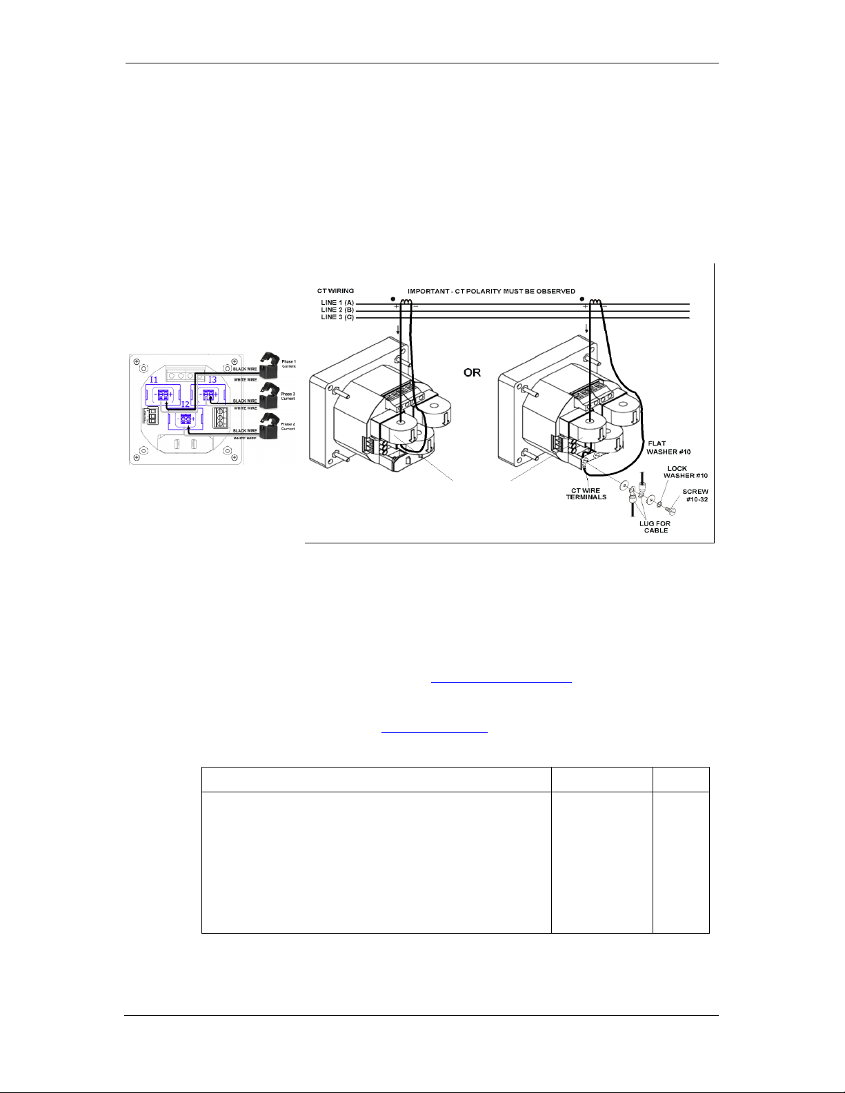
3. Connect to the external CT by passing the external
CT wire through the meter CT core. Observe the
arrow that indicates the current direction.
4. In case of a retrofit application where each external
CT ends with two wires:
• Pass one wire through the meter CT core.
• Connect the wire to one of the meter termination
screws.
• Connect the second wire from the external CT to
the termination screw.
5. Connect the measured voltage inputs
6. Connect COM1 – RS-485 communication port
7. Connect the Power Supply inputs using 1.5
mm2/14AWG-dedicated wires.
PowerSmart+ Power Quality Meter 5
Page 6
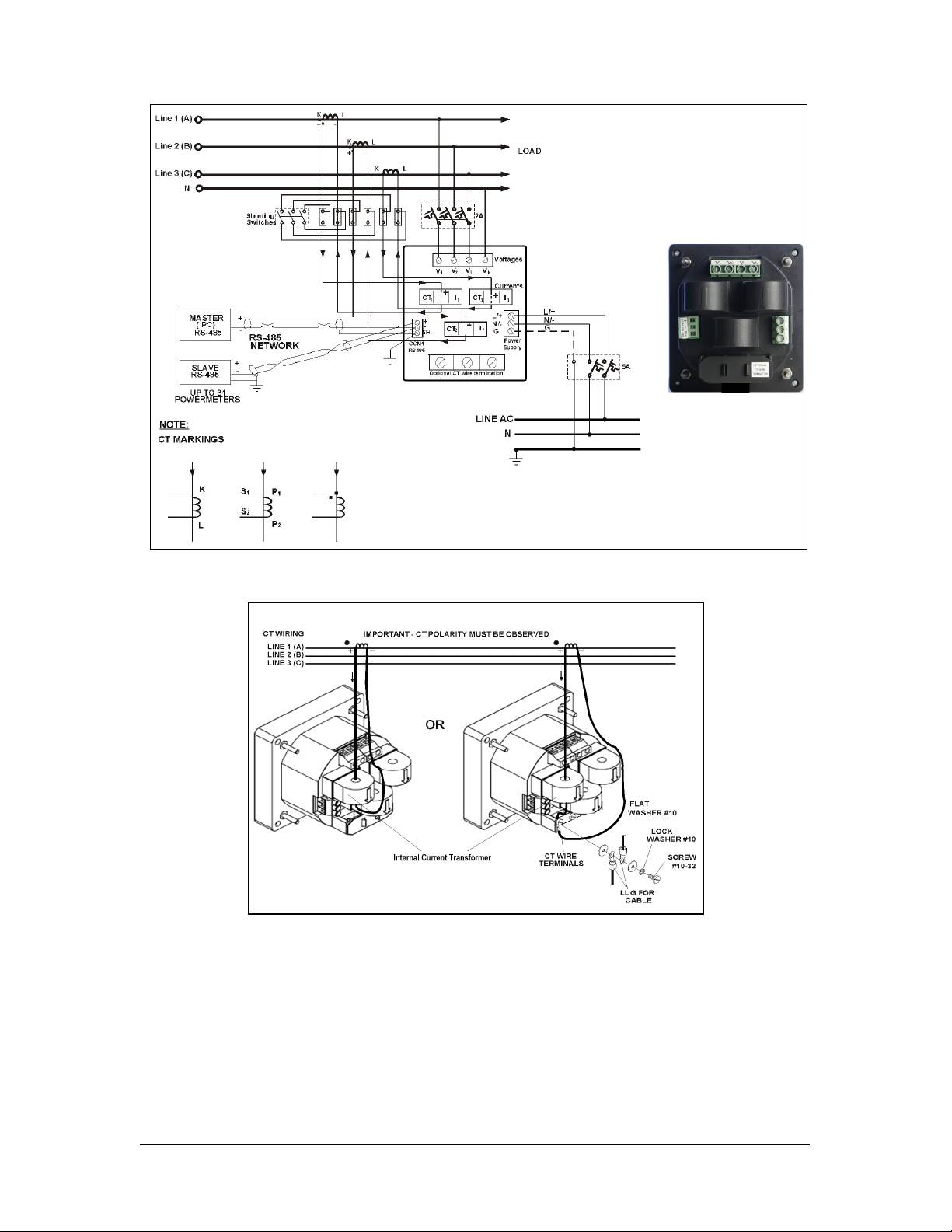
Common Wiring Mode: 4LL3 or 4Ln3
Internal CT wiring
6 PowerSmart+ Power Quality Meter
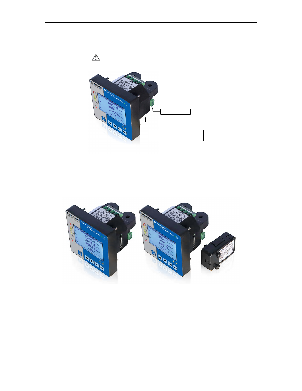
Page 7
Module co
nnector cover
RS-485
Terminals
REMOVE
External CT wiring
To connect an Option module:
1. Assemble the module on the meter.
2. Power the PowerSmart+ PQM unit on.
COVER
TO
CONNECT
MODULE
Remove Module Connector cover
before assembling module
Assembling a module
To operate the PowerSmart+ PQM:
1. Perform device diagnostics.
PowerSmart+ Power Quality Meter 7
Page 8

2. Configure the device through the PowerSmart+ PQM
unit front panel display.
2. Configuring the PowerSmart+ PQM remotely
1. Install the Power Software tool on your PC.
2. Configure the Power Software database for your
meter.
3. Configure the Power Software communications
settings.
4. Upgrade the meter firmware if a new version is
available.
5. Set up the meter using the Power Software
application software.
6. Configure your security settings through the meter
security setup.
7. Configure your communication protocol settings.
8. Configure Billing/TOU registers.
At this stage, the PowerSmart+ PQM should be ready for operation.
8 PowerSmart+ Power Quality Meter
Page 9

Chapter 1 General Information Features
Table of Contents
Chapter 1 General Information..........................................................................12
1.1 Features.......................................................................................................................12
1.2 Available Options.......................................................................................................14
Digital I/O............................................................................................................ 14
Analog Output ...................................................................................................... 15
Additional Communication Port – COM2...................................................................15
TOU - Battery-Operated Clock Unit..........................................................................15
1.3 Customized Options..................................................................................................15
Device Resolution.................................................................................................. 15
Energy Rollover .................................................................................................... 15
Display Options.....................................................................................................15
1.4 Measured Parameters ..............................................................................................16
Chapter 2 Installation..........................................................................................18
2.1 Site Requirements.....................................................................................................18
2.2 Package Contents......................................................................................................18
2.3 Mechanical Installation.............................................................................................18
Panel Mounting.....................................................................................................19
DIN Rail Mounting.................................................................................................19
2.4 Electrical Installation.................................................................................................21
Typical Installation ................................................................................................21
Terminals.............................................................................................................22
Power Source Connection....................................................................................... 22
Voltage Input connection .......................................................................................23
Current Input Connection....................................................................................... 23
Wiring Diagrams................................................................................................... 24
2.5 I/O Connections........................................................................................................29
4DI/2DO Module................................................................................................... 29
12DI/4RO Module .................................................................................................30
4AO Module - Analog Outputs.................................................................................32
TOU module – RTC and 4 Digital Inputs...................................................................33
2.6 Communications Connections.................................................................................34
COM1 RS-485 Connection......................................................................................35
ETH module – COM2 Ethernet Connection................................................................35
RS-232/422-485 module – COM2 Connection ..........................................................36
Chapter 3 Using Front Display............................................................................38
3.1 Display Operations....................................................................................................38
Navigation Buttons................................................................................................ 39
Navigating in Data Display Mode.............................................................................40
Status Indicators...................................................................................................40
Display Features...................................................................................................41
3.2 Data Displays..............................................................................................................43
TEST Mode Data Display........................................................................................43
Billing Period Data Displays .................................................................................... 44
Measurements Maximum Demand Data Display.......................................................47
Measurements Data Display...................................................................................48
Measurements Minimum/Maximum Data Display......................................................51
Measurements Energy Data Display ........................................................................52
Harmonics Display ................................................................................................53
PowerSmart+ Power Quality Meter 9
Page 10

Chapter 1 General Information Features
Waveform Display................................................................................................. 54
Phasor Display......................................................................................................54
Digital I/O............................................................................................................ 54
Device Control Display........................................................................................... 55
Basic Settings Display............................................................................................56
Device Info Display ............................................................................................... 56
Load Bar Graph ....................................................................................................56
Energy Pulse LED.................................................................................................. 57
Port Activity LEDs..................................................................................................57
3.3 Device Setup...............................................................................................................58
Entering the Password........................................................................................... 58
Viewing and Changing Setup Options ...................................................................... 58
Viewing and Changing Setup Options ...................................................................... 59
Chapter 4 Using Power Software.......................................................................60
4.1 Installing Power Software.......................................................................................60
4.2 Creating a New Site for your Meter........................................................................60
4.3 Setting up Communications ....................................................................................61
Communicating through a Serial Port ......................................................................62
Communicating through the Internet ......................................................................63
4.4 Setting Up the Meter.................................................................................................64
Preparing Setups for the Meter ............................................................................... 64
Downloading Setups to the Meter ...........................................................................65
Uploading Setups from the Meter............................................................................65
4.5 Authorization..............................................................................................................65
Chapter 5 Configuring the PowerSmart+ PQM..............................................67
5.1 Configuring Communications..................................................................................67
Setting Up Serial Communication Ports....................................................................67
Setting Up Ethernet............................................................................................... 69
Setting Up GPRS Network ......................................................................................71
Setting Up eXpertPower Client................................................................................ 72
Setting Up TCP Notification Client............................................................................ 73
5.2 General Meter Setup .................................................................................................75
Basic Meter Setup .................................................................................................75
Transformer Correction.......................................................................................... 77
Device Options .....................................................................................................78
Configuring Digital Inputs....................................................................................... 80
Configuring Relay Outputs......................................................................................81
Configuring Analog Outputs.................................................................................... 83
Configuring Counters............................................................................................. 84
Configuring Alarm/Control Setpoints........................................................................ 85
Configuring the Display.......................................................................................... 89
Updating the meter Clock.......................................................................................90
Local Time Settings ............................................................................................... 90
5.3 Configuring Meter Security......................................................................................92
5.4 Configuring Billing/TOU ...........................................................................................95
Configuring Billing/Tariff Registers...........................................................................95
Configuring the Daily Tariff Schedule.......................................................................97
Configuring the Season Tariff Schedule....................................................................97
5.5 Configuring Recorders..............................................................................................99
Configuring Meter Memory .....................................................................................99
Configuring the Event Recorder ............................................................................ 101
Configuring the Data Recorder.............................................................................. 101
5.6 Configuring Communication Protocols...............................................................104
10 PowerSmart+ Power Quality Meter
Page 11

Chapter 1 General Information Features
Configuring Modbus............................................................................................. 104
Configuring DNP3................................................................................................ 105
Chapter 6 Device Control and Upgrading......................................................108
6.1 Resetting Accumulators, Maximum Values and Files......................................108
6.2 Viewing and Clearing Device Diagnostics..........................................................110
6.3 Viewing Communication Status and Statistics..................................................111
6.4 Remote Relay Control............................................................................................111
6.5 Upgrading Device Firmware.................................................................................112
Chapter 7 Monitoring Meters........................................................................... 115
7.1 Viewing Real-time Data.........................................................................................115
7.2 Viewing Real-time Min/Max Log .........................................................................117
7.3 Viewing Real-time Waveforms............................................................................ 118
7.4 Viewing Real-time Harmonic Spectrum.............................................................119
Chapter 8 Retrieving and Storing Files ..........................................................123
8.1 Uploading Files on Demand..................................................................................123
8.2 Using the Upload Scheduler..................................................................................124
8.3 Viewing Files On-line..............................................................................................126
8.4 Exporting Files......................................................................................................... 126
Exporting Files in COMTRADE and PQDIF Formats................................................... 126
Exporting Files in Excel Format ............................................................................. 127
8.5 Archiving Files .........................................................................................................128
Chapter 9 Viewing Files.................................................................................... 129
9.1 Operations with Files .............................................................................................129
9.2 Viewing Options......................................................................................................129
Customizing Views .............................................................................................. 129
Working with Tables............................................................................................ 130
Working with Graphic Windows............................................................................. 130
9.3 Viewing the Event Log...........................................................................................132
9.4 Viewing the Data Log............................................................................................. 134
Appendix A Technical Specifications .............................................................. 135
Appendix B Analog Output Parameters......................................................... 141
Appendix C Setpoint Triggers and Actions.................................................... 143
Appendix D Parameters for Data Monitoring and Logging......................... 146
Appendix E Billing/TOU Profile Log File......................................................... 155
Appendix F Data Scales....................................................................................157
Appendix G Device Diagnostic Codes.............................................................158
Index................................................................................Error! Bookmark not defined.
PowerSmart+ Power Quality Meter 11
Page 12
Chapter 1 General Information Features
Chapter 1 General Information
⇒
1.1 Features
Multifunctional 3-phase Power Meter
The PowerSmart+ PQM is a compact, multi-function, three-phase AC
Powermeter specially designed to meet the requirements of users ranging
from electrical panel builders to substation operators.
The PowerSmart+ PQM measuring and power supply inputs comply
with Measuring Category II
The PowerSmart+ PQM unit includes:
• A 3.5" Monochrome Graphic LCD display enabling easy reading of
local meters, and can be predefined in different languages.
• A standard RS-485 communication port and a second optional
Ethernet port. These ports allow local and remote automatic
meter readings and setup through the supplemental
communication or user data acquisition software.
• Different communication options for remote communications with
the meter. These options enable LAN and Internet communication
with the unit.
The PowerSmart+ PQM is suitable for mounting on both 4-inch round and
92×92mm square cutouts.
• 3 voltage inputs and 3 current transformer-isolated AC inputs for
direct connection to power line or via potential and current
transformers
• True RMS, volts, amps, power, power factor, neutral current,
voltage and current unbalance, frequency
• Ampere/Volt demand meter
• 25/50/60/400 Hz measurement capabilities
Billing/TOU Energy Meter
• Class 0.5S IEC 62053-22 four-quadrant active and reactive
energy polyphase static meter
12 PowerSmart+ Power Quality Meter
Page 13

Chapter 1 General Information Features
• Three-phase total and per phase energy measurements; active,
reactive and apparent energy counters
• Time-of-Use, 4 totalization and tariff energy/demand registers x 8
tariffs, 4 seasons x 4 types of days, 8 tariff changes per day,
• One–time easy programmable tariff calendar schedule
• Automatic daily energy and maximum demand profile log for total
and tariff registers
Harmonic Analyzer
• Voltage and current THD, current TDD and K-Factor, up to 40th
order harmonic
• Voltage and current harmonic spectrum and angles
Real-time Waveform Capture
• Real-time “scope mode” waveform monitoring capability
• Simultaneous 6-channel one-cycle waveform capture at a rate of
64 samples per cycle
Programmable Logical Controller
• Embedded programmable controller
• 16 control setpoints; programmable thresholds and delays
• Relay output control (see Available Options)
• 1-cycle response time
Event and Data Recording
• Non-volatile memory for long-term event and data recording
• Event recorder for logging internal diagnostic events and setup
changes
• Two data recorders; programmable data logs on a periodic basis;
automatic daily energy and maximum demand profile log
Digital I/O
• Optional four digital inputs with 1-ms scan time; automatic
recording of last five digital input change events with timestamps
(see the PowerSmart+ PQM Modbus Reference Guide)
• Optional two relay outputs with 1-cycle update time; unlatched,
latched, pulse and KYZ operation; energy pulses
Display
• 3.5 inch Monochrome Graphic LCD display with 240 x 128 dots
resolution, adjustable update time backlit and user defined
brightness setting
• Auto-scroll option with adjustable page exposition time; autoreturn to a default page
• LED bar graph showing percent load with respect to userdefinable nominal load current
Real-time Clock
• Internal clock with 20-second retention time
• Optional battery-operated clock unit (see Available Options)
PowerSmart+ Power Quality Meter 13
Page 14

Chapter 1 General Information Available Options
Communications
• Standard 2-wire RS-485 communication port; MODBUS RTU,
DNP3 communication protocols
• Optional second communication port (see Available Options);
MODBUS RTU, MODBUS/TCP, DNP3, DNP3/TCP communication
protocols
• eXpertPower client (see Setting Up eXpertPower Client)
• TCP notification client for communicating with a remote
MODBUS/TCP server on events or periodically on a time basis
(with the Ethernet module or with the RS-232 module using an
external GPRS modem, see Setting Up TCP Notification Client)
Meter Security
• Password security for protecting meter setups and accumulated
data from unauthorized changes
Upgradeable Firmware
• Easy upgrading device firmware through a serial or Ethernet port.
Software Support
• Power Software – free meter configuration and data acquisition
tool
• eXpertPowerTM – Cloud AMR software services
1.2 Available Options
The PowerSmart+ PQM can be provided with an optional expansion
module from the following list:
• Digital I/O
• Analog outputs
• TOU - Battery-operated clock unit
• Ethernet communication port
• PROFIBUS DP communication port
• RS-232/RS-422/RS-485 communication port
• GPRS communication port
Digital I/O
The PowerSmart+ PQM digital I/O expansion module provides:
4DI/2DO module
• 4 dry contact digital inputs (DI) for monitoring external contacts
and receiving pulses from energy, water, and gas meters
• Programmable de-bounce time; 1-ms scan time.
• 2 electro-mechanical or solid-state relay outputs (RO) for alarms
and controls, and for output energy pulses; unlatched, latched
and pulse operations, failsafe operation for alarm notifications;
programmable pulse width; direct remote relay control through
communications; 1-cycle update time.
12DI/4DO module
• 12 dry contact digital inputs (DI) for monitoring external contacts
and receiving pulses from energy, water, and gas meters
14 PowerSmart+ Power Quality Meter
Page 15

Chapter 1 General Information Customized Options
• Programmable de-bounce time; 1-ms scan time.
• 4 electro-mechanical relay outputs (RO) for alarms and controls,
and for output energy pulses; unlatched, latched and pulse
operations, failsafe operation for alarm notifications;
programmable pulse width; direct remote relay control through
communications; 1-cycle update time.
Analog Output
The PowerSmart+ PQM analog output (AO) expansion module provides:
• 4 optically isolated analog outputs with an internal power supply;
• Options for 0-20mA, 4-20mA, 0-1mA, and ± 1mA output; 1-cycle
update time.
Additional Communication Port – COM2
A second COM2 communication port can be ordered as an expansion
module. COM2 options available:
• Ethernet 10/100BaseT port; MODBUS/TCP , DNP3/TCP
communications protocols
• PROFIBUS DP port
• RS-232/RS-422/RS-485 port; MODBUS RTU, DNP3
communication protocols;
TOU - Battery-Operated Clock Unit
The TOU module provides:
• A precise clock with battery backup; 6-year clock retention time
• 4 dry contact digital inputs (DI) for monitoring external contacts
and receiving pulses from energy, water and gas meters;
programmable de-bounce time; 1-ms scan time.
1.3 Customized Options
Presentation of data on the front display and via communications can be
customized to best suit the user application.
Device Resolution
A low or high-resolution option can be selected for the presentation of
voltage, current, and power for use in high and low power applications.
See Measurement Units for more information.
Energy Rollover
The energy rollover limit can be changed in the meter to provide 4-digit to
9-digit energy resolution. See Device Options in Chapter 5 for details. The
meter display is capable of showing full 9-digit energy counters using two
LED windows.
Display Options
Different display options are available for customization to be used in dark
or non-safe locations, or in places that are hardly accessible for
PowerSmart+ Power Quality Meter 15
Page 16

Chapter 1 General Information Measured Parameters
observation. See Configuring the Display in Chapter 5 for more
information.
1.4 Measured Parameters
Table 1: Measured and Displayed Parameters
Parameter Display Comm. Analog Pulse Alarm
1-cycle Real-time Measurements
RMS Voltage per phase
RMS Current per phase
kW per phase
kvar per phase
kVA per phase
Power Factor per phase
Total kW
Total kvar
Total kVA
Frequency
Neutral Current
Total Power Factor
Voltage & Current unbalance
1-sec Average Measurements
RMS Voltage per phase
RMS Current per phase
kW per phase
kvar per phase
kVA per phase
Power Factor per phase
Total kW
Total kvar
Total kVA
Total Power Factor
Frequency
Neutral Current
Voltage & Current unbalance
Amps & Volt Demands
Ampere & Volt Demand per phase
Ampere Maximum Demand per phase
Voltage Maximum Demand per phase
Power Demands
kW Accumulated Demand Import & Export
kvar Accumulated Demand Import & Export
kVA Accumulated Demand
kW Demand Import & Export
kvar Demand Import & Export
kVA Demand
kW Sliding Demand Import & Export
kvar Sliding Demand Import & Export
kVA Sliding Demand
kW Predicted Demand Import & Export
kvar Predicted Demand Import & Export
kVA Predicted Demand
kW Maximum Demand Import
16 PowerSmart+ Power Quality Meter
Page 17

Chapter 1 General Information Measured Parameters
Parameter Display Comm. Analog Pulse Alarm
kW Maximum Demand Export
kvar Maximum Demand Import
kvar Maximum Demand Export
kVA Maximum Demand
Total Energy
E, EH
Total kWh Import & Export
Total kvarh Import & Export
Total kvarh Net
Total kVAh
Energy per Phase
kWh Import per phase
kvarh Import per phase
kVAh per phase
TOU Registers
4 TOU energy registers (kWh and kvarh
import & export, kVAh, 4 pulse sources)
4 TOU maximum demand registers
8 tariffs, 4 seasons x 4 types of day
Harmonic Measurements
Voltage THD per phase
Current THD per phase
Current TDD per phase
K-factor per phase
Voltage harmonics per phase up to order 40
Current harmonics per phase up to order 40
Voltage harmonic angles up to order 40
Current harmonic angles up to order 40
Fundamental Component
EH
Voltage and Current per phase
kW, PF per phase
kvar, KVA per phase
Total kW, PF
Total kvar, KVA
Min/Max Logging
Min/Max A, V, total kW, kvar, kVA, PF
Min/Max Frequency, Neutral current
Phase Rotation
Voltage and Current Phase Angles
Day and Time
Pulse Counters
Digital Inputs (optional)
Relay Outputs (optional)
Remote Relay Control (optional)
Alarm Triggers/Setpoints
Self-diagnostics
PowerSmart+ Power Quality Meter 17
Page 18
Chapter 2 Installation Site Requirements
Chapter 2 Installation
This chapter discusses the following types of physical installations for the
PowerSmart+ PQM Powermeter:
• Mechanical Installation
• Electrical Installation
• I/O Connections
• COM Port Connections.
2.1 Site Requirements
• Environmental conditions: as specified in Technical Specifications
in Appendix A
• Electrical requirements: as specified in Technical Specifications in
Appendix A
See Technical Specifications in Appendix A for more details
2.2 Package Contents
The PowerSmart+ PQM Powermeter package contains the following items:
• PowerSmart+ PQM unit
• Technical Documentation in CD Rom
• Optional accessories (depending on the options ordered, if any)
• Cables
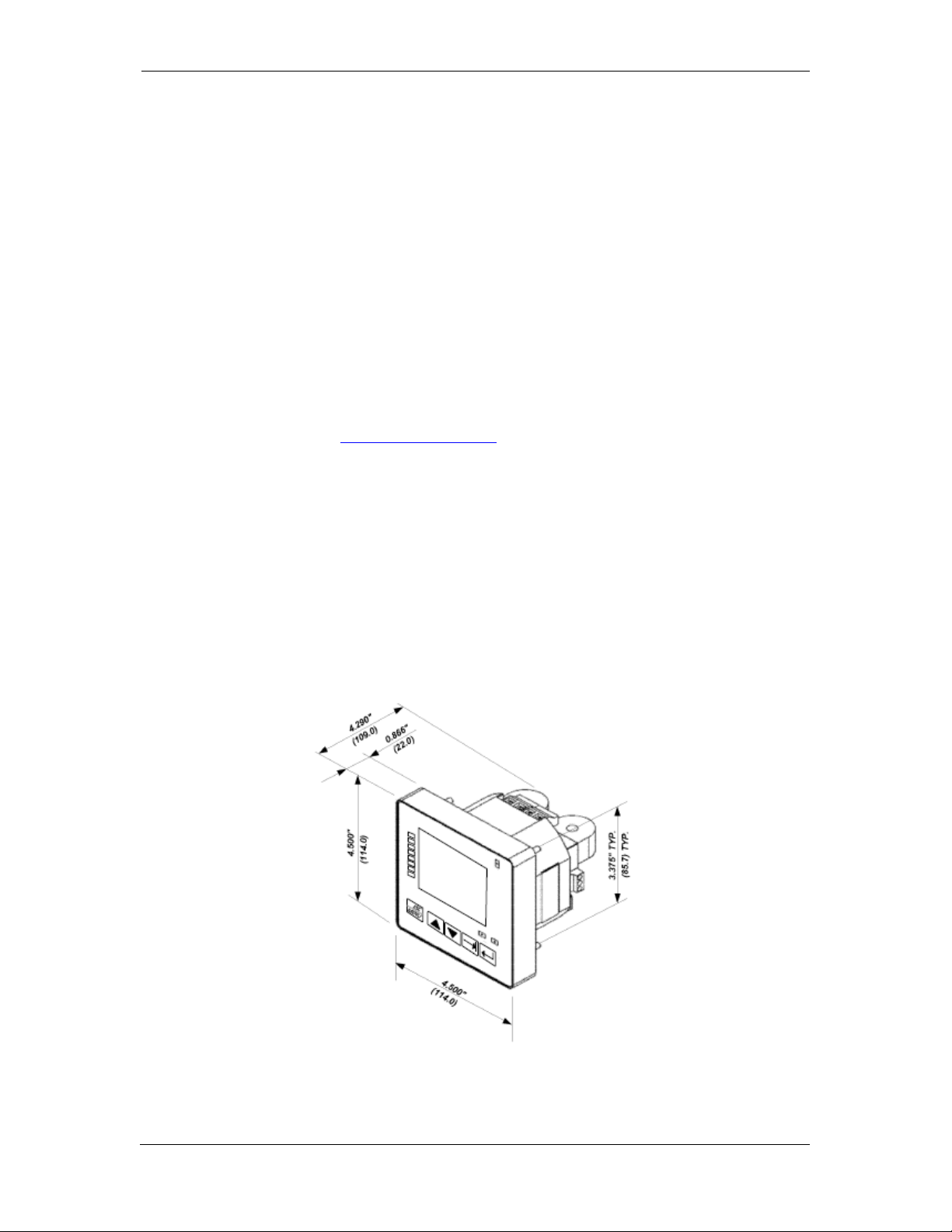
2.3 Mechanical Installation
Refer to the figures provided in this section to properly perform the
mechanical installation.
Figure 2-1. Dimensions
18 PowerSmart+ Power Quality Meter
Page 19
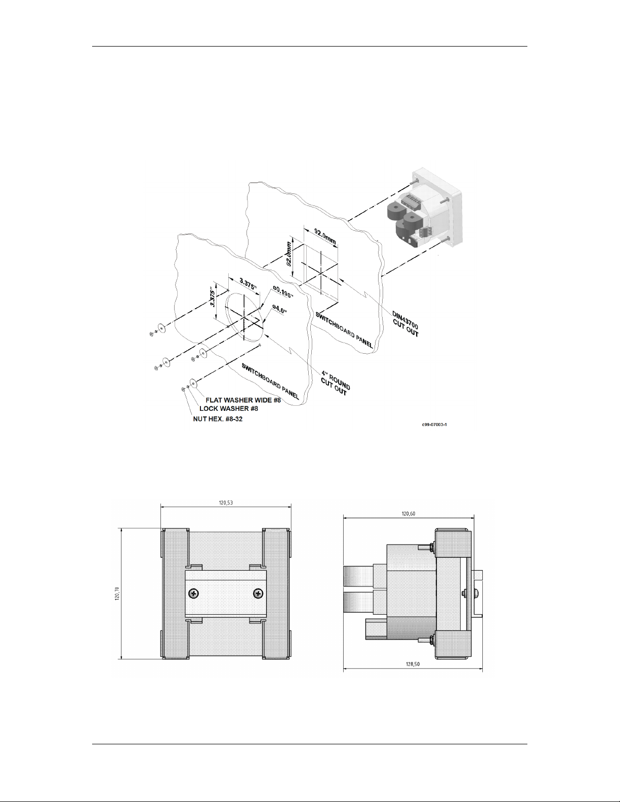
Chapter 2 Installation Mechanical Installation
Panel Mounting
To mount the meter in cutout (ANSI 4" round or DIN 92x92mm
square cutout):
1. Position the meter in the cutout.
2. Affix the meter using washers and nuts. (Add short text on Panel
Mounting, a heading should always have text)
DIN Rail Mounting
The PowerSmart+ PQM can be mounted on a 35-mm DIN rail.
Figure 2-3. Dimensions
Figure 2-2. Mounting
PowerSmart+ Power Quality Meter 19
Page 20
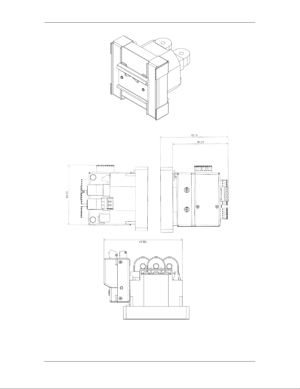
Chapter 2 Installation Mechanical Installation
Figure 2-4. DIN Rail Mounting
Figure 2-5 PowerSmart+ PQM with 12DI/4RO module
20 PowerSmart+ Power Quality Meter
Page 21
Chapter 2 Installation Electrical Installation
2.4 Electrical Installation
The equipment installation shall conform to the following
instructions:
a) a switch or circuit-breaker shall be included in the building
installation;
b) It shall be in close proximity to the equipment and within
easy reach of the OPERATOR;
c) It shall be marked as the disconnecting device for the
equipment.
Before installing, ensure that all incoming power sources
are shut OFF. Failure to observe this practice can result in
serious or even fatal injury and damage to equipment.
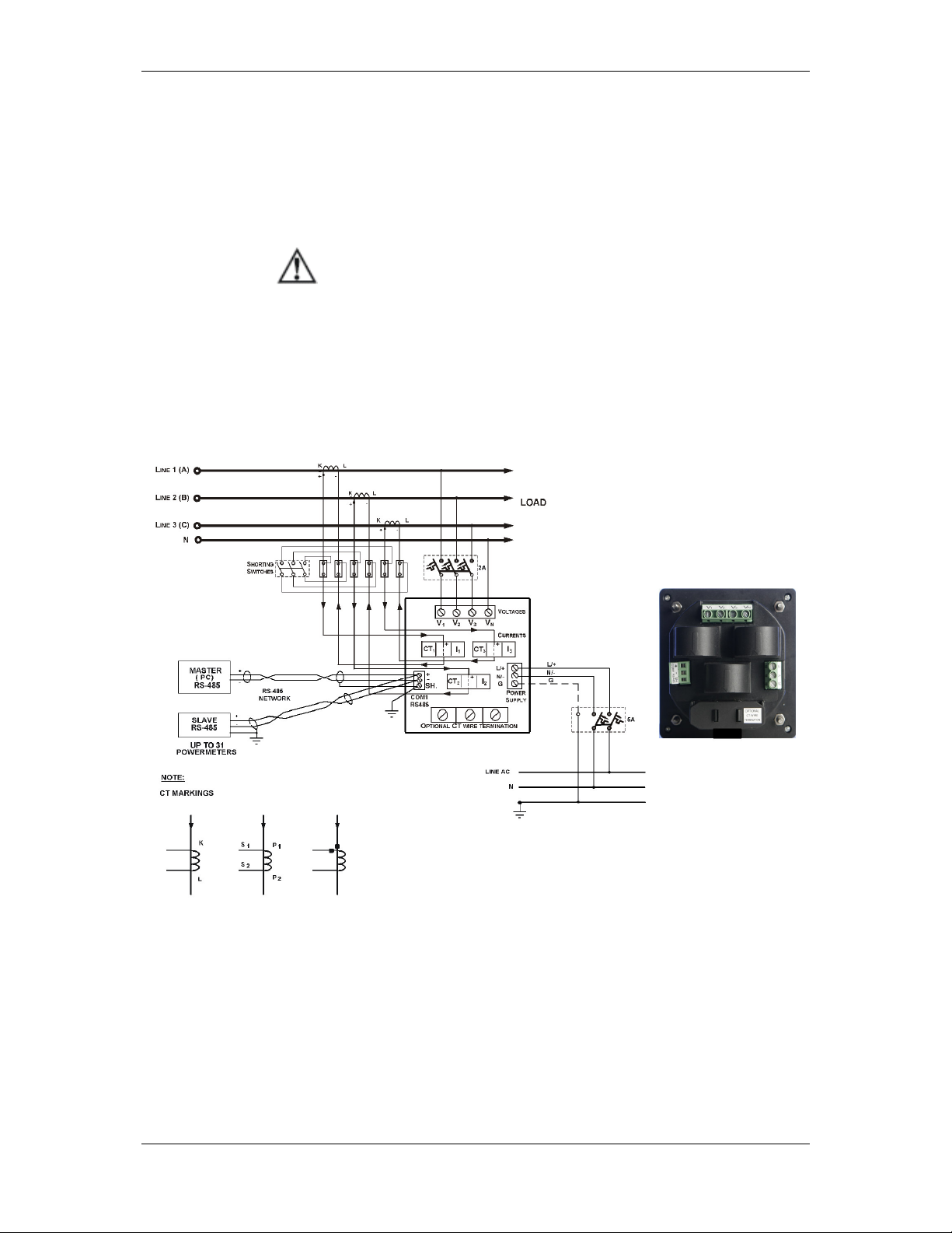
Typical Installation
Figure 2-6 Typical Installation Diagram
PowerSmart+ Power Quality Meter 21
Page 22
Chapter 2 Installation Electrical Installation
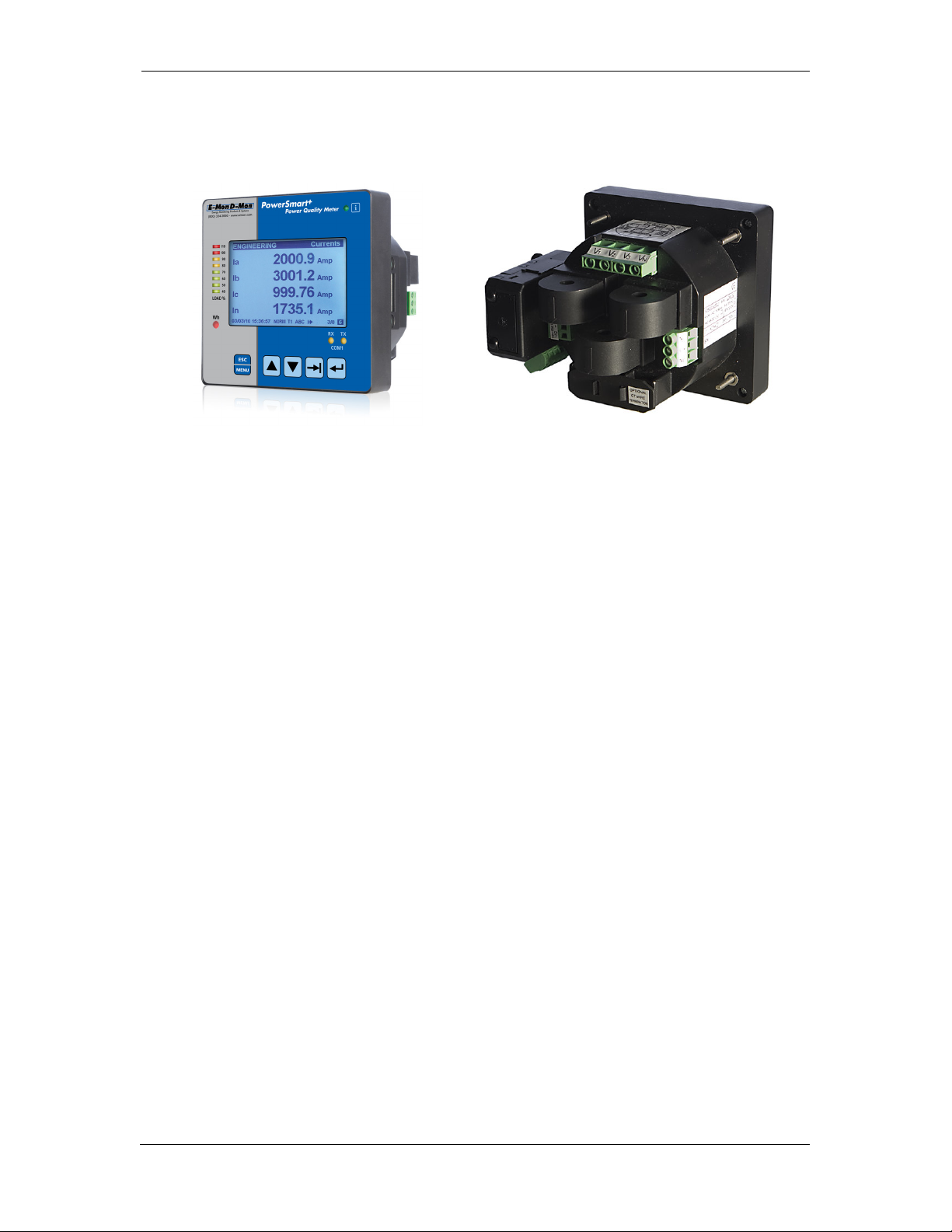
Terminals
Figure 2-7. Terminals -Rear View
Power Source Connection
The equipment installation shall conform to the following
instructions:
a) a switch or circuit-breaker shall be included in the building
installation;
b) It shall be in close proximity to the equipment and within
easy reach of the OPERATOR;
c) It shall be marked as the disconnecting device for the
equipment.
Before installing, ensure that all incoming power sources
are shut OFF. Failure to observe this practice can result in
serious or even fatal injury and damage to equipment.
COMMUNICATION TERMINAL
OPTION MODULE CONNECTOR
The power source can be a dedicated fuse, or a monitored voltage if it is
within the instrument power supply range.
To connect an AC power supply:
1. Connect the Line wire to terminal L/+.
2. Connect the Neutral wire to terminal N/-.
To connect to a DC power supply:
1. Connect the positive wire to terminal L/+
2. Connect the negative wire to terminal N/-.
22 PowerSmart+ Power Quality Meter
Page 23
Chapter 2 Installation Electrical Installation
2
N
3
2
V
3
Voltages
2
N
3
2V3
Voltages
Voltage Input connection
The equipment installation shall conform to the following
instructions:
a) a switch or circuit-breaker shall be included in the building
installation;
b) It shall be in close proximity to the equipment and within
easy reach of the OPERATOR;
c) It shall be marked as the disconnecting device for the
equipment.
Before installing, ensure that all incoming power sources
are shut OFF. Failure to observe this practice can result in
serious or even fatal injury and damage to equipment.
690V Inputs (Standard)
400
690
400
690
400
V
690
V
V
V
V
690V inputs are usually used with direct connection. Use any of the seven
wiring configurations shown in Figures 2-8 through 2-15.
120V Inputs (Option U)
120
120
120
120
120
V
120
V
V
V
V
120V inputs usually imply use of a potential transformer (PT). The PT
requires use of any of the four wiring configurations shown in Figures 2-7
through 2-10.
Current Input Connection
V
V
The PowerSmart+ PQM series provide two different CT connections:
• Using internal CT, the PowerSmart+ PQM does not have current
terminals
• Using highly accurate external CT, the PowerSmart+ PQM provides
current terminals
PowerSmart+ Power Quality Meter 23
Page 24
Chapter 2 Installation Electrical Installation
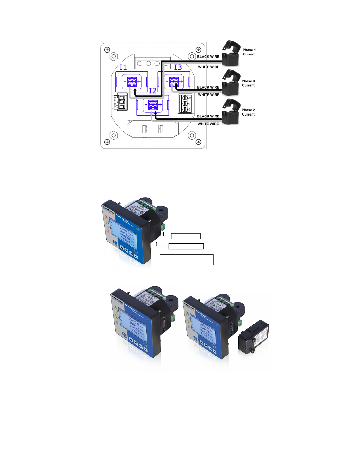
To connect the internal CT to the high current external CT, pass the
external CT wire through the meter CT core, see Figure 2-8a for details
and observe the arrow that indicates the current direction.
In case of a retrofit application where each external CT ends with two
wires:
1. Pass one wire through the meter CT core.
2. Connect the wire to one of the meter termination screws.
3. Connect the second wire from the external CT to the termination
screw to close the loop.
With highly Accurate external
Current Transformer
Internal Current Transformer
Figure 2-8 Current Input Connection
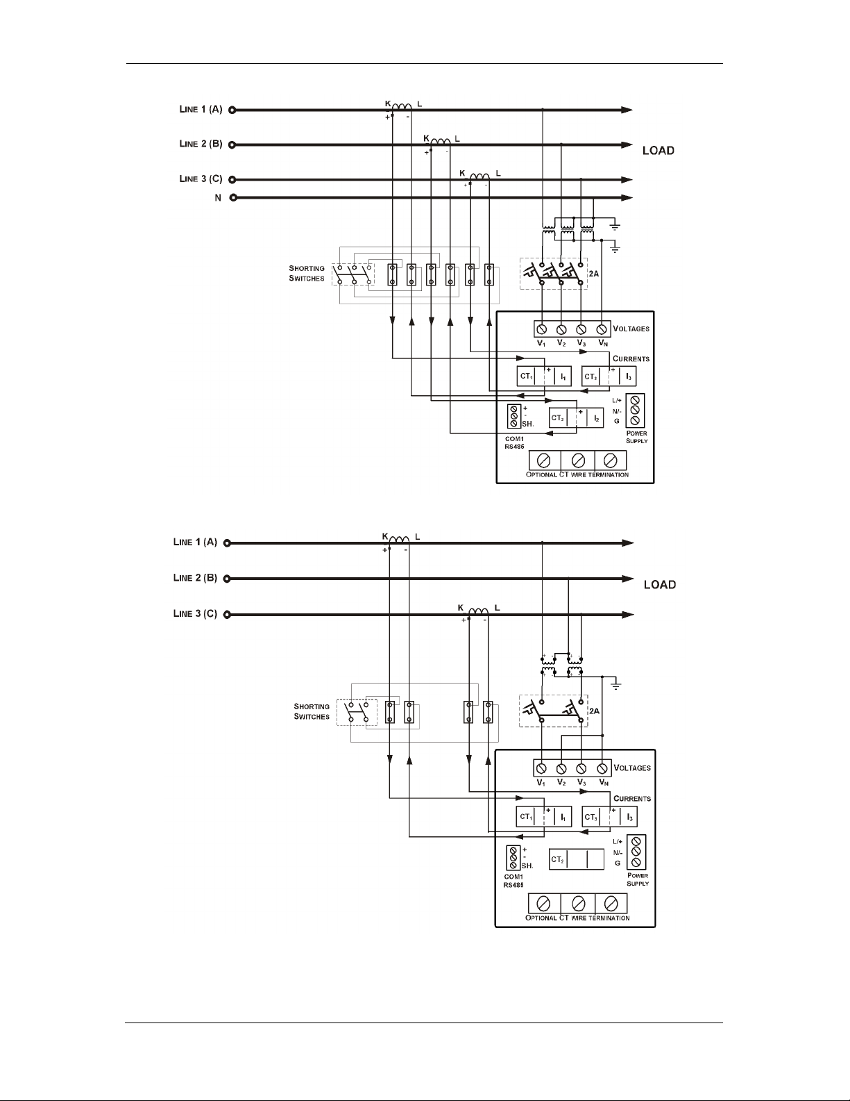
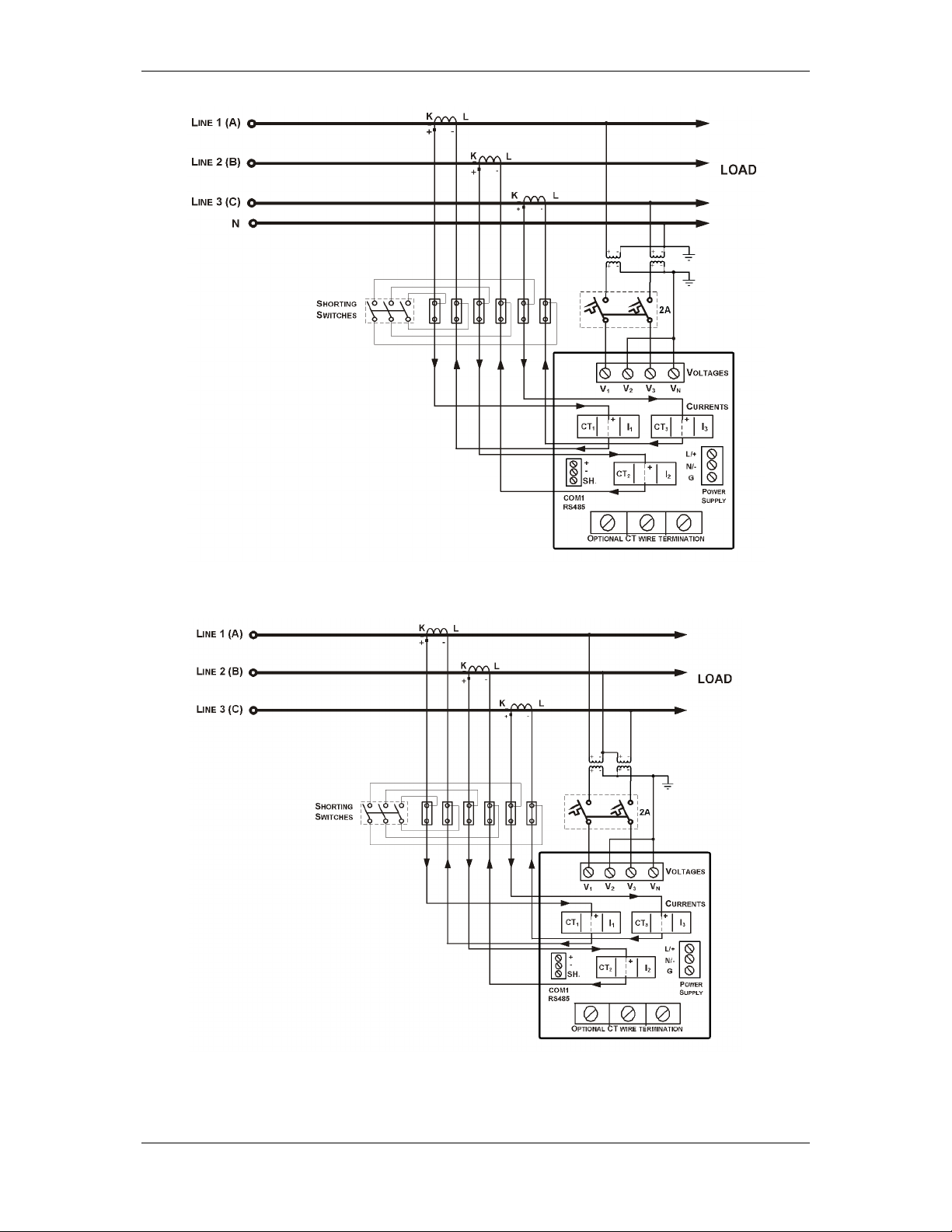
Wiring Diagrams
For AC input ratings, see Technical Specifications in Appendix A for more
details.
Table 2 presents the available wiring configurations in the meter. For
more details, see Basic Meter Setup in Chapter 5.
Table 2: Wiring Configurations
Wiring Configuration Setup Code Figure
3-wire 2-element Delta direct connection using 2 CTs 3dir2 2-8
4-wire 3-element Wye direct connection using 3 CTs 4Ln3 or 4LL3 2-9
4-wire 3-element Wye connection using 3 PTs, 3 CTs 4Ln3 or 4LL3 2-10
3-wire 2-element Open Delta connection using 2 PTs, 2 CTs 3OP2 2-11
4-wire 2½-element Wye connection using 2 PTs, 3 CTs 3Ln3 or 3LL3 2-12
3-wire 2½-element Open Delta connection using 2 PTs, 3 CTs 3OP3 2-13
4-wire 3-element Delta direct connection using 3 CTs 4Ln3 or 4LL3 2-14
3-wire 2½-element Broken Delta connection using 2 PTs, 3 CTs 3bLn3 or 3bLL3 2-15
24 PowerSmart+ Power Quality Meter
Page 25
Chapter 2 Installation Electrical Installation
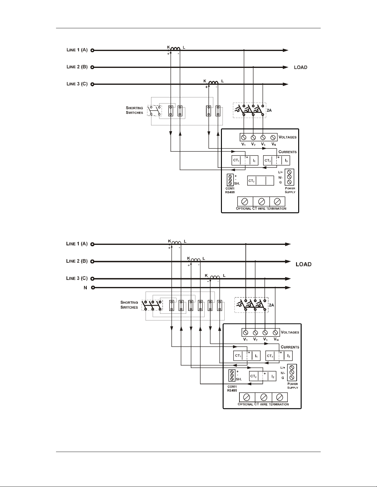
Figure 2-9 3-Wire 2-Element Delta Direct Connection Using 2 CTs (Wiring Mode = 3dir2)
Figure 2-10 4-Wire Wye 3-Element Direct Connection Using 3 CTs (Wiring Mode = 4LL3 or 4Ln3)
PowerSmart+ Power Quality Meter 25
Page 26
Chapter 2 Installation Electrical Installation
Figure 2-11 4-Wire Wye 3-Element Connection Using 3 PTs, 3 CTs (Wiring Mode = 4LL3 or 4Ln3)
Figure 2-12 3-Wire 2-Element Open Delta Connection Using 2 PTs, 2 CTs (Wiring Mode = 3OP2)
26 PowerSmart+ Power Quality Meter
Page 27
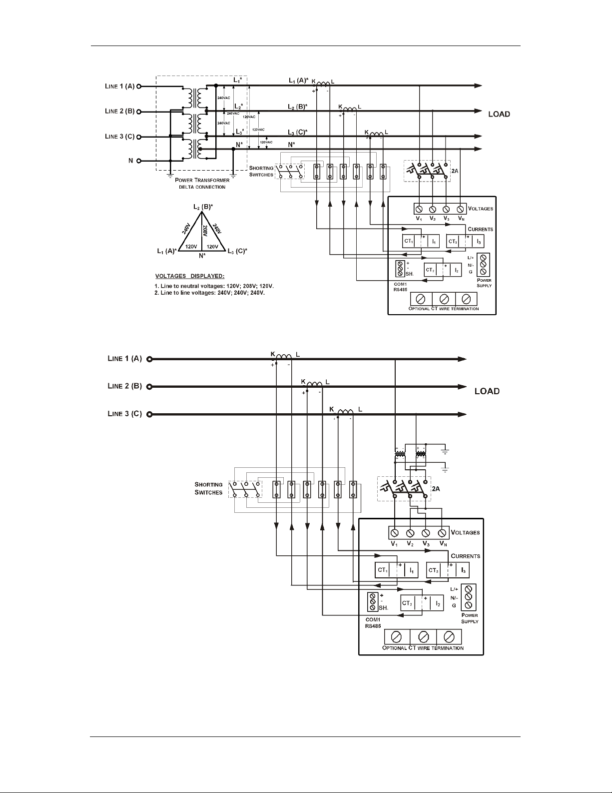
Chapter 2 Installation Electrical Installation
This configuration provides accurate power measurements only if the voltages are balanced.
Figure 2-13 4-Wire Wye 2½-Element Connection Using 2 PTs, 3 CTs (Wiring Mode = 3LL3 or 3Ln3)
Figure 2-14 3-Wire 2½-Element Open Delta Connection Using 2 PTs, 3 CTs (Wiring Mode = 3OP3)
PowerSmart+ Power Quality Meter 27
Page 28
Chapter 2 Installation Electrical Installation
Figure 2-15 4-Wire 3-Element Delta Direct Connection Using 3 CTs (Wiring Mode = 4LL3 or 4Ln3)
Figure 2-16 3-Wire 2½-Element Broken Delta Connection Using 2 PTs, 3 CTs (Wiring Mode = 3bLn3 or
3bLL3)
28 PowerSmart+ Power Quality Meter
Page 29
Chapter 2 Installation I/O Connections
REMOVE
2.5 I/O Connections
Before I/O Module installation ensure that all incoming
power sources are shut OFF. Failure to observe this practice
can result in serious or even fatal injury and damage to
equipment.
Figure 2-17 Module Connector Cover – Before Module Assembly
For I/O ratings, see Technical Specifications in Appendix A.
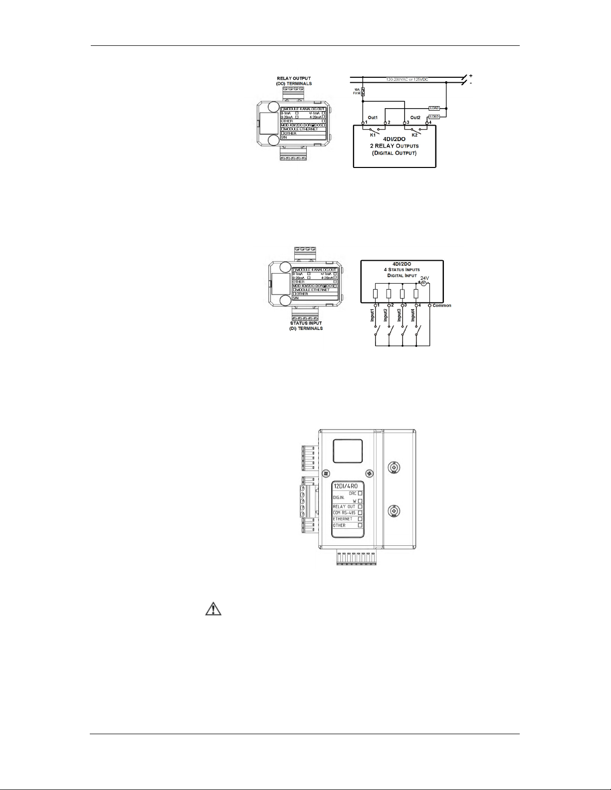
4DI/2DO Module
COVER
TO
CONNECT
MODULE
RS-485 Terminals
Module connector cover
Remove Module Connector cover
before assembling module
Figure 2-18 4DI/2DO Module Assembly
Relay Outputs
There are two relay outputs provided for energy pulsing, alarms, or
remote control.
PowerSmart+ Power Quality Meter 29
Page 30
Chapter 2 Installation I/O Connections
Figure 2-19 Relay Output Connection
Digital Inputs
Four optically isolated status inputs are provided for status monitoring,
pulse counting, external power demand period, and time synchronization.
12DI/4RO Module
The 12DI/4RO module can be equipped with optional communication port
COM2 – ETHERNET or RS-422/485.
Before I/O Module installation ensure that all incoming power
sources are shut OFF. Failure to observe this practice can
result in serious or even fatal injury and damage to equipment.
Figure 2-20 Digital Input Connection
Figure 2-21 12DI/4RO Module
Relay Outputs
There are four electro-mechanic relay outputs provided for energy
pulsing, alarms, or remote control.
30 PowerSmart+ Power Quality Meter
Page 31

Chapter 2 Installation I/O Connections
Figure 2-22 Relay Output Connection
Digital Inputs
12 optically isolated status inputs are provided for status monitoring,
pulse counting, external power demand period, and time synchronization.
Figure 2-23 12 Digital Input Connection
PowerSmart+ Power Quality Meter 31
Page 32

Chapter 2 Installation I/O Connections
4AO Module - Analog Outputs
The 4AO module has four optically isolated analog outputs with an internal
power supply and current output options of 0-20 mA and 4-20 mA
(current loop load of up to 500 Ohm), 0-1 mA and ±1 mA (2mA 100%
overload, current loop load of up to 5 kOhm).
Figure 2-24: Analog Output Connection
It is recommended to connect unused Analog output
channels to Common terminal.
• The 4AO module TERMINAL is for use only with equipment
which has no live parts which are ACCESSIBLE
• The RATING of the insulation of the external equipment for
use with the 4AO module, shall comply according to
Installation Category II for insulation to be suitable for
SINGLE FAULT CONDITION
⇒
• The external equipment TERMINAL connection type is
normally terminal block for wire size 14 AWG (up to 1.5
mm2)
• The type of equipment that might be connected to the
TERMINAL is:
− Programmable Logic Controller for automation – PLC
− Digital or Analog meter
32 PowerSmart+ Power Quality Meter
Page 33

Chapter 2 Installation I/O Connections
TOU module – RTC and 4 Digital Inputs
The TOU provides a battery-operated real time clock (RTC) with four
optically isolated inputs for status monitoring, time synchronization, pulse
counting, and external power demand period.
Digital Inputs
Figure 2-25: TOU Digital Input Connection
TOU – Battery Replacement
WARNING!
Only qualified personnel familiar with the instrument and its
associated electrical equipment must perform the RTC battery
backup replacement.
To replace the CR1632 RTC battery:
1. Remove the TOU module from the PowerSmart+ PQM
compartment
2. Open the TOU MODULE case by applying a flat screwdriver at
three snap-in slit (1, 2 and 3), as shown in Figure 2-26.
3. Remove the old battery by lifting up the battery holder
retractable tab.
4. Place the new CR1632 battery into the battery holder while
holding up the battery holder retractable tab in such a way that
the (+) battery pole is toward the battery holder, as shown in
Figure 2-26.
PowerSmart+ Power Quality Meter 33
Page 34

Chapter 2 Installation Communications Connections
Figure 2-26: TOU RTC Battery Replacement
2.6 Communications Connections
Before installing the Communication Module, ensure that all
incoming power sources are shut OFF. Failure to observe this
practice can result in serious or even fatal injury and damage
to equipment.
Several communication options are available for the PowerSmart+ PQM:
• COM1: RS-485
• COM2, on optional communication module:
Ethernet 10/100BaseT
RS-232 or RS-422/485
A connection to the Ethernet connector is made through a cable adaptor
provided with your meter.
A full description of the communication protocols is found in the
PowerSmart+ PQM protocol guides that come with your meter.
The 12DI/4RO module can be equipped with optional communication
⇒
port COM2 – ETHERNET or RS-422/485
34 PowerSmart+ Power Quality Meter
Page 35

Chapter 2 Installation Communications Connections
The RATING of the insulation of the external equipment
COM1 RS-485 Connection
Figure 2-27: COM1 RS-485 2-Wire Connection
The connector is removable with three captured-wire terminals.
ETH module – COM2 Ethernet Connection
Figure 2-28: COM2 Ethernet Connection
• The ETH module TERMINAL is for use only with equipment
which has no live parts which are ACCESSIBLE
⇒
•
for use with the ETH module, shall comply according to
Installation Category II for insulation to be suitable for
SINGLE FAULT CONDITION
PowerSmart+ Power Quality Meter 35
Page 36

Chapter 2 Installation Communications Connections
• The external equipment TERMINAL connection type is
RJ-45
• The type of equipment that might be connected to the
TERMINAL is:
− Personal Computer – PC or LAPTOP
− 10/100Base-T LAN HUB and/or Switch
RS-232/422-485 module – COM2 Connection
Figure 2-29: COM2 RS-232 connection
36 PowerSmart+ Power Quality Meter
Page 37

Chapter 2 Installation Communications Connections
Figure 2-30: COM2 RS-422/485 and 12DI/4RO-RS-422/485 modules connection
• The RS-232/422-485 module TERMINALS are for use only
with equipment which has no live parts which are
ACCESSIBLE
• The RATING of the insulation of the external equipment for
use with The RS-232/422-485 module, shall comply
according to Installation Category II for insulation to be
⇒
suitable for SINGLE FAULT CONDITION
• The external equipment TERMINAL connection type is
normally terminal block for wire size 14 AWG (up to 1.5
mm²) – RS-422/485 port and DB9 male-to-female cable
more than 22 AWG (0.3mm²)
• The type of equipment that might be connected to the
TERMINAL is:
− Personal Computer – PC or LAPTOP
PowerSmart+ Power Quality Meter 37
Page 38

Chapter 3 Using Front Display Display Operations
Chapter 3 Using Front Display
This chapter provides PowerSmart+ PQM Power meter series front panel
information and operating procedures.
Figure 3-1: PowerSmart+ PQM Unit
3.1 Display Operations
The PowerSmart+ PQM has a high-contrast graphical LCD display with
backlight for local data read outs, meter setup and servicing.
The display operates in two modes:
The display is normally updated once per second.
• Multi-page data display mode with Auto-Scroll
feature allows you to scroll through display screens
and pages to view various billing, instrumentation
and status data.
• Programming mode allows you to enter menu-driven
device setups for inspecting and changing factory
set meter parameters, or resetting maximum
demands, counters and device diagnostics
messages.
38 PowerSmart+ Power Quality Meter
Page 39

Chapter 3 Using Front Display Display Operations
Navigation Buttons
The PowerSmart+ PQM is provided with five navigation buttons
as described below:
Button Operation
The SELECT/ENTER button - function changes depending on
the display mode:
• While navigating to submenus, pressing the
• In "Basic Setup" or "Device Setup" menus, while
SELECT/ENTER
TAB – browse from submenu to next submenu or
move to required digit setup
PAGE DOWN– scrolling DOWN
PAGE UP – scrolling UP
ESCAPE
SELECT/ENTER button selects the highlighted line
menu
changing device parameters pressing the
SELECT/ENTER button stores the parameter
changes into the device
The TAB button - function changes depending on the
current display:
• In display data mode – monitoring, pressing the
TAB button moves from current data display to next
data display
• For instance, in "Basic Setup" selecting "CT Primary
Current A", pressing the TAB button moves to next
digit to be set
The UP/DOWN scroll buttons - function changes
depending on the current display:
• In display menu mode – pressing the UP/DOWN
scroll buttons, navigates between each
function/parameter in menus screens
• In display data mode – pressing the UP/DOWN
scroll buttons, navigates from current display data
screen to next display data screen
The ESC/MENU button - function changes depending on the
current display:
• In display menu mode – while in sub-menu,
pressing the ESC/MENU button, moves to upper
menu screen
• In display data mode – pressing the ESC/MENU
button, moves to Main Menu screen
PowerSmart+ Power Quality Meter 39
Page 40

Chapter 3 Using Front Display Display Operations
Display Sub
-
menu name
Sub-menu Parameter display
Operating mode
Present date and time
Present tariff rate indicator
No load/Power
flow
Navigating in Data Display Mode
The PowerSmart+ PQM provides multiple pages data displays. Your
present location is indicated upper bar as shown in the following picture.
See Data Displays for the full displays list.
Use UP/DOWN scroll buttons to scroll through data displays.
Status Indicators
Graphical icons on the bottom status bar give immediate meter status
indication and show the present tariff rate.
The present date and time are indicated at left on the status bar. The date
order can be changed according to local rules via the "Real Time Clock"
device setup menu.
Voltage phase presence
indicators
direction indicator
Operating Mode Indicator
The mode indicator gives information on the load presence and shows the
direction of active power.
Indicator Icon Description
Normal mode
Test mode
Tariff Rate Indicator
The tariff rate indicator (T1 through T8) shows the currently active tariff
rate.
No Load/Power Flow Direction Indicator
The power flow indicator gives information on the load presence and
shows the direction of active power.
Indicator
Icon
No load.
Description
40 PowerSmart+ Power Quality Meter
Page 41

Chapter 3 Using Front Display Display Operations
Direct active power flow – delivered active energy.
Reversed active power flow – received active energy.
Phase Presence Indicators
Phase presence indicators “123” show the status of either V1-V2-V3
phase-to-neutral voltages in line-to-neutral wiring modes, or V12-V23V31 phase-to-phase voltages in line-to-line wiring modes.
Indicator
Icon
123
1 3
123
1–3
If the phase voltage is below the defined voltage dip threshold, its
corresponding phase indicator is blinking.
If the phase voltage is either missing or below the voltage interruption
threshold, the phase indicator is replaced with a dash
Display Features
While energizing the device the display will show an init screen followed
by phase-voltages measurements as described below:
The PowerSmart+ PQM display has a number of programmable features
that can be disabled, enabled and adjusted via the meter Display Setup
(see Display Setup in Chapter 5).
Backlight
A short press on any button while the display backlight is off switches the
backlight on.
The backlight stays on as long as you selected in the display setup and
then dims to conserve power. The backlight time is factory set to 1 minute
and can be programmed from 1 to 10 minutes. You can temporarily set
the backlight to continuous operation if you need to work in dark for more
time.
Contrast
The contrast can be adjusted via the meter Display Setup (see Display Setup
in Chapter 5).
Auto-Return
If the Auto-Return feature is enabled and no button is pressed for the
programmable Auto-Return interval (1 to 30 minutes for data displays;
fixed at 5 minutes for setup menus), the display automatically returns to
the default page from any other data display or a setup menu.
Description
All voltages are present and above the voltage dip threshold.
Blinking phase indicator – the phase voltage is below the
defined voltage dip threshold. Possibly indicates an incorrect
meter nominal voltage setting (see Basic Meter Setup in
Chapter 5).
Dashed phase indicator - the phase voltage is either missing or
below the voltage interruption threshold.
PowerSmart+ Power Quality Meter 41
Page 42

Chapter 3 Using Front Display Display Operations
If the Auto-Scroll feature is enabled, the display immediately enters the
auto scroll sequence.
Auto-Scroll
If the Auto-Scroll feature is enabled, the data display automatically scrolls
through all pages of all data displays that are included into the
programmable auto-scroll sequence. The scroll interval is adjustable in the
range of 2 to 30 seconds. The scroll sequence may include all or only
selected displays.
The display automatically enters auto scrolling if no button is pressed for
the Auto-Return interval when the Auto-Return feature is enabled or in 1
minute if this feature is disabled. In the last case, the scroll sequence is
restored from the point where it was interrupted.
To stop auto scrolling, press briefly any button if the backlight is on; else
press briefly any button twice since the first press only sets the backlight
on and does not affect auto scrolling.
Auto-Scroll is not operational in TEST mode.
Measurement Units
The PowerSmart+ PQM has a selectable resolution for volts, amps and
powers presented on the front display and via communications. See
Device Options in Chapter 5 for information on selecting the data
resolution in the PowerSmart+ PQM .
Low Resolution Option
Currents are displayed in whole amperes below 10,000 A, and in kilo
amperes above 10,000 A.
Measurement units for voltage and power depend on the voltage
connection scheme:
• For direct wiring (PT=1) or wiring via PT with the PT ratio up to
and including 4.0, voltages are displayed in volts, and power in
kilowatts.
• For the PT ratio above 4.0, voltages are displayed in kilovolts with
three decimal places, and power in megawatts with three decimal
places.
High Resolution Option
Currents are displayed in amperes with up to two decimal places below
10,000 A, and in kilo amperes above 10,000 A.
Measurement units for voltage and power depend on the voltage
connection scheme:
• When direct wiring is used (PT=1), voltages are displayed in volts
with one decimal place, and power in kilowatts with three decimal
places.
• When wiring via PT is used with the PT ratio up to and including
4.0, voltages are displayed in volts, and power in whole kilowatts.
• For the PT ratio above 4.0, voltages are displayed in kilovolts with
three decimal places, and power in megawatts with three decimal
places.
The small round “Kilo” and “Mega” LEDs light up showing the appropriate
measurement units for a displayed page.
42 PowerSmart+ Power Quality Meter
Page 43

Chapter 3 Using Front Display Display Operations
Primary and Secondary Volts
Volts can be displayed in primary (default) or secondary units. The volts
display mode can be changed through the display setup (see Configuring
the Display).
Phase Power Readings
In configurations with the neutral wire, in addition to total three-phase
powers, the meter can show per-phase power readings. By default, they
are disabled. See Configuring the Display on how to enable per-phase
power readings in your meter.
Fundamental Component
The PowerSmart+ PQMEH can display total displacement power factor and
active power for the fundamental component if it is enabled through the
display setup (see Configuring the Display).
When phase power readings are allowed, the PowerSmart+ PQMEH also
displays per-phase displacement power factor and active power for the
fundamental component.
3.2 Data Displays
The PowerSmart+ PQM has 8 multi-page data displays listed in the
following table.
Data Display
Menu
Sequence
1 Measurements Present 7 Measurements Data Displays:
2 Harmonics V/I individual harmonics and Harmonics
3 Waveforms Vn/In Waveforms with THD value
4 Phasor Voltage and current phasors diagram
5 Digital I/O Status of counters, Digital IN and relays
6 Device Control Diagnostics and Alarms displays
7 Basic Settings Device configuration display
8 Device Info Device model, identification, firmwares
Display Label Display Contents
TEST Mode Data Display
The TEST data display is shown in TEST mode in place of the billing period
data displays.
V, I, P, S, Q, PF, Max. DMD, MIN/MAX,
Energy and Billing/TOU
Spectrum
out
version, COM1,COM2
TEST mode display:
test LED pulse rate in secondary Wh/imp;
test kWh and kvarh energy readings in primary units
with an extended 0.001 kWh resolution.
TEST mode setup menu is enabled in Device
Setup/Device Options menu.
PowerSmart+ Power Quality Meter 43
Page 44

Chapter 3 Using Front Display Display Operations
Billing Period Data Displays
The PowerSmart+ PQM provides billing period data displays for energy
and general purpose volume data as m³, cf or Ccf calculated using Digital
Input for water and/or gas meter application.
Only registers you selected in the billing/TOU register setup and tariff
rates listed in the TOU daily profiles are included (see Configuring
Billing/Tariff Registers and Configuring the Daily Tariff Schedule in
Chapter 5).
The following example demonstrates the present billing period displays for
two configured billing registers (kWh imported and kvarh imported) and
for three active tariff rates. The actual register contents in your
installation may be different depending on your selection of register
sources.
Each billing period display lists all total and tariff energy, maximum
demand and cumulative maximum demand registers for all configured
billing registers and all active tariffs. Use the UP/DOWN button to scroll to
the desired Billing/TOU period register display
Register 1 - total readings:
Total Import Active energy data.
Billing period according to TOU predefined profile
(Reg1 for TOU actve energy and Reg2 for TOU
reactive energy are predefined TOU/Register factory
setup, can be changed by user, see Configuring
Billing/Tariff Registers and Configuring the Daily
Tariff Schedule in Chapter 5)
Register 1 – tariff 1 readings:
Total Import Active energy data.
Register 1 – tariff 2 readings:
Total Import Active energy data.
44 PowerSmart+ Power Quality Meter
Page 45

Chapter 3 Using Front Display Display Operations
Register 1 – tariff 3 readings:
Total Import Active energy data.
Register 2 - total readings:
Total Export Active energy data.
Register 2 – tariff 1 readings:
Total Export Active energy data.
Register 2 – tariff 2 readings:
Total Export Active energy data.
Register 2 – tariff 3 readings:
Total Export Active energy data.
Register 3 - total readings:
Total Import Reactive energy data
PowerSmart+ Power Quality Meter 45
Page 46

Chapter 3 Using Front Display Display Operations
Register 3 – tariff 1 readings:
Total Import Reactive energy data.
Register 3 – tariff 2 readings:
Total Import Reactive energy data.
Register 3 – tariff 3 readings:
Total Import Reactive energy data.
Register 4 - total readings:
Total Export Reactive energy data
Register 4 – tariff 1 readings:
Total Export Reactive energy data.
Register 4 – tariff 2 readings:
Total Export Reactive energy data.
46 PowerSmart+ Power Quality Meter
Page 47

Chapter 3 Using Front Display Display Operations
Register 4 – tariff 3 readings:
Total Export Reactive energy data.
Measurements Maximum Demand Data Display
Maximum demand displays show measurements maximum demands (not
billing maximum demands) for powers, voltages, currents and total
harmonics. Each quantity is displayed with the date and time of the last
update. Use the UP/DOWN button to scroll to the desired Max. DMD data
display
Import kW maximum demand
Import (inductive) kvar maximum demand
Import kVA maximum demand
Export kW maximum demand
Export (inductive) kvar maximum demand
Export kVA maximum demand
V1-V3 maximum demand
Indicate V12-V31 voltage in line-to-line
configurations.
I1-I3 and In maximum demand
PowerSmart+ Power Quality Meter 47
Page 48

Chapter 3 Using Front Display Display Operations
Measurements Data Display
Measurements data represent general instrumentation data you can use
while installation and inspecting the meter. Use phase angles displays to
check the order of phases when connecting wires to the meter terminals.
Use the UP/DOWN button to scroll to the desired data display
Phase-to-neutral voltages. Only displayed in 4-wire
configurations with a neutral.
Phase-to-phase voltages
Phase-to-neutral voltages maximum demand with
time stamp
Phase voltage/current angle
Line frequency
48 PowerSmart+ Power Quality Meter
Page 49

Chapter 3 Using Front Display Display Operations
Voltage unbalance, %
Phase voltage THD
Indicate phase-to-phase voltage THD in line-to-line
configurations
Phase and neutral currents
Phase and neutral currents maximum demand with
time stamp
Current unbalance, %
Phase Current Total Demand Distorsion, %
PowerSmart+ Power Quality Meter 49
Page 50

Chapter 3 Using Front Display Display Operations
Phase Current THD, %
Total powers and power factor
Total powers maximum demand export
Total powers maximum demand import
Phase 1 powers and power factor
Phase 2 powers and power factor
50 PowerSmart+ Power Quality Meter
Page 51

Chapter 3 Using Front Display Display Operations
Phase 3 powers and power factor
Measurements Minimum/Maximum Data Display
Minimum/Maximum displays show measurements minimum/maximum for
powers, voltages, currents, power factor and frequency. Each quantity is
displayed with the date and time of the last update. Use the UP/DOWN
button to scroll to the desired Min/Max data display
Phase currents minimum/maximum values with
time stamp.
Neutral current minimum/maximum values with
time stamp.
Phase-to-neutral voltages minimum/maximum
values with time stamp.
Phase-to-phase voltages minimum/maximum values
with time stamp.
PowerSmart+ Power Quality Meter 51
Page 52

Chapter 3 Using Front Display Display Operations
Total powers minimum/maximum values with time
stamp.
Total power factor minimum/maximum value with
time stamp.
Line frequency minimum/maximum value with time
stamp.
Measurements Energy Data Display
Energy displays show measurements total import/export for energy and
phases energy. Use the UP/DOWN button to scroll to the desired energy
data display
Total import energy.
Total export energy.
52 PowerSmart+ Power Quality Meter
Page 53

Chapter 3 Using Front Display Display Operations
Phase 1 import energy.
Phase 2 import energy.
Phase 3 import energy.
Harmonics Display
Harmonics display shows individual harmonics distortion for phase
voltages and current, and phase voltage/current harmonic spectrum
graphs. Use the UP/DOWN button to scroll to the specific harmonic
number or voltage and current channels harmonic spectrum.
Individual harmonics phase voltages and currents,
%
Per-phase current harmonic spectrum I1-I3
PowerSmart+ Power Quality Meter 53
Page 54

Chapter 3 Using Front Display Display Operations
Waveform Display
The waveform display shows per-phase voltage and current waveforms
and V/I values + THD. Use the UP/DOWN button to scroll through the
phases.
Per-phase voltage and current waveforms
Phasor Display
The Phasor display shows a three-phase network Phasor diagram. All
phase angles are given relatively to the V1 channel.
Three-phase voltage and current Phasor diagram
Digital I/O
The Digital I/O display shows three sub-menus: "Digital Inputs" display to
show status of each digital input, "Pulse/Event Counters" display to count
external pulses or setpoint events, or as time counters to count setpoint
operation time, "Relay Outputs" display to show status of each relay
output. Use the UP/DOWN button to move from one display to another.
Digital Inputs status
external pulses or setpoint events counter, or as
time counters to count setpoint operation time
54 PowerSmart+ Power Quality Meter
Page 55

Chapter 3 Using Front Display Display Operations
Relay outputs status
Device Control Display
The device control display shows two sub-menus: "Diagnostics" and
Alarms". The diagnostics display shows device diagnostic messages
recorded as a result of the meter self-test diagnostics during start-up and
operation, the alarm display shows a list of operated alarm setpoints
along with the alarm trigger labels if there are alarms recorded during
meter operation.
Device Control sub-menu, use the UP/DOWN button
to select whether Diagnostics or Alarms displays
List of diagnostics messages
List of alarms messages
If there are diagnostic messages, the diagnostic green led on the
device panel flashes until you clear the device diagnostics. Some of the
diagnostics events are cleared automatically as the event source
disappears. See Device Diagnostic Codes in Appendix H for a full list of
diagnostic messages and their meanings. See Clearing Device Diagnostics
for information on how to clear the device diagnostics from the display
and via Power Software.
The diagnostic Led indication can be disabled or enabled via the Display
Setup menu.
PowerSmart+ Power Quality Meter 55
Page 56

Chapter 3 Using Front Display Display Operations
Basic Settings Display
The basic settings display shows basic device settings that can be required
for immediate inspecting while meter testing and at the time of
installation. Use the UP/DOWN button to scroll through the settings
Device wiring mode (see Basic Meter Setup for full
list of wiring modes), external potential transformer
ratio and the nominal device voltage.
Primary ratings of the external current transformers
(main and auxiliary current inputs) and the nominal
device frequency
Power demand period (number of blocks x block
demand period), and voltage and ampere demand
periods.
Device Info Display
The device info display provides different service information that may be
required for meter identification and inspection, like product/module and
firmware information, I/O module type, communication settings, and so
on. Use the UP/DOWN button to scroll through the device info.
Load Bar Graph
Meter identification info
Meter communication info
The load bar graph displays the amount, in percent (40% to 110%), of
the present current load with respect to user-defined nominal load
current. The reference nominal current can be set up in amps through the
display setup (see Configuring the Display). If it is set to 0 (default), the
current load is referenced to the specified CT primary current.
56 PowerSmart+ Power Quality Meter
Page 57

Chapter 3 Using Front Display Display Operations
Energy Pulse LED
The PowerSmart+ has a red “Energy Pulse” LED for calibration. It flashes
at a constant rate when a load is applied to the meter.
There are two modes of LED operation:
• NORMAL mode: the LED pulses indicate imported Wh at a rate
of 1,000 pulses per kWh
• TEST mode: the LED pulses indicate either imported Wh, or
imported (inductive) varh at a rate of 10,000 pulses per
kWh/kvarh
The energy test mode can be enabled through the Device Options setup.
When in test mode, the energy and demand accumulators do not account
for consumed energy.
Port Activity LEDs
The meter has two green LEDs “RX” and “TX”, which indicate activity on
the COM1 communication port. The LEDs flash when the port is receiving
or transmitting data.
PowerSmart+ Power Quality Meter 57
Page 58

Chapter 3 Using Front Display Device Setup
3.3 Device Setup
The PowerSmart+ PQM setup is menu-driven. The device provides 12
menus that allow local accessing a limited number of meter setups and
control functions listed in the following table. Access to particular menus is
granted depending on the password you entered if enabled.
Menu Label Menu Function
Reset Reset of engineering maximum demands,
Real Rime Clock RTC clock setup
Display Setup Display setup
Basic Setup Basic device setup
Device options Device options setup
COM1 Setup COM1 serial port setup
Local Settings Local settings
Setpoint Setup
Password Setup Meter passwords setup
device diagnostics, meter and battery
operation time counters and failure counters
Entering the Password
The Setup Change menu can be secured by a four-digit user password.
You can change the password and enable password protection through the
Access Control menu (see Configuring Meter Security). The meter is
primarily shipped with the password preset to 0 and password protection
disabled.
If password protection is enabled, you are prompted for a password when
entering the setup change menu.
To enter the password:
1. Select the desired digit field using the TAB button
2. Select the desired digit using the
UP/DOWN button
3. Press ENTER to confirm the
password.
If the password you entered is correct, you are moved to the Main menu,
otherwise you return back to the Device Setup menu.
58 PowerSmart+ Power Quality Meter
Page 59

Display Setup
Auto Scroll
Disabled
2
3
4
5
6
Chapter 3 Using Front Display Device Setup
Viewing and Changing Setup Options
Once you entered a correct password you are moved to the Device Setup
menu.
The Device Setup menu consists of sub-menus list.
To select a desired menu entry from the menu list:
Device Setup
Reset
Real Time Clock
Display Setup
Basic Setup
Device Options
COM1 Setup
COM2 Setup
Device Setup
Reset
Real Time Clock
Display Setup
Basic Setup
Device Options
COM1 Setup
COM2 Setup
Display Setup
Auto Scroll
Auto Return 5
Backlight 1
Diagnostics LED Disabled
Phase Powers Disabled
Fundamental Powers Disabled
Contrast 15
Display Setup
Auto Scroll
Auto Return 5
Backlight 1
Diagnostics LED Disabled
Phase Powers Disabled
Fundamental Powers Disabled
Contrast 15
5
Use the UP/DOWN button - to scroll through the menu list to
the desired menu entry
Press the SELECT/ENTER button - to enter the selected submenu.
Parameters that are represented by values can be changed in two ways:
By pressing the SELECT/ENTER button - , a new sub-menu
appears by presenting possible values to be selected
By pressing the TAB button - , the highlight cursor moves to
the actual value to be changed
Use the UP/DOWN button - to scroll through the desired value,
then press the SELECT/ENTER button - to store the selected value
Disabled
Note: While being in the Device Setup operation mode, the PowerSmart+
PQM display will return to normal operation, i.e. move to data display,
during idle operation of one minute
PowerSmart+ Power Quality Meter 59
Page 60

Chapter 4 Using Power Software Installing Power Software
Chapter 4 Using Power Software
The support Power Software software is a configuration and data
acquisition tool that allows you to configure all of the PowerSmart+ PQM
features, monitor your meters on-line, retrieve recorded files and view
reports. Power Software can communicate with your PowerSmart+ PQM
via a serial port and via the Ethernet.
This chapter gives information on how to install and run Power Software
on your computer, and how to prepare information for your meter using
Power Software.
See Chapter 5 Configuring the PowerSmart+ PQM for instructions on how
to configure particular features in your meter. Refer to Chapters 7 and 8
for instructions on retrieving data from the meters and viewing reports.
4.1 Installing Power Software
You need Power Software V1.4 Build 4 or higher to take an advantage of
the meter data logging options.
To install Power Software on your PC:
1. Insert the installation CD supplied with your meter into CD drive.
2. Open My Computer on your Desktop.
3. Click on your CD drive icon, select the Power Software directory,
and then double click on Setup (shown as an Application type
file).
4. Follow InstallShield® Wizard instructions on the screen.
Power Software is installed by default to the C:\Power Software folder.
When installation is complete, the Power Software icon appears on your
Desktop. Double click on the Power Software icon to run Power Software.
For general information on how to work with Power Software, see the
“Power Software Getting Started” guide supplied on the installation CD.
4.2 Creating a New Site for your Meter
Power Software keeps all communication and configuration data for your
meter in a configuration database called a site database. During
configuration, store all setup data to the site database so that Power
Software recognizes device properties regardless of whether the meter is
online or offline.
To communicate with the meters, create a separate site database for each
device.
To create a new database for your meter:
1. Select Configuration from the Tools menu.
60 PowerSmart+ Power Quality Meter
Page 61

Chapter 4 Using Power Software Setting up Communications
PSE
Figure 4-1: Configuration Dialog Box – Instrument Setup Tab
2. Click the Sites button on the right-hand-side.
3. From the Look in box, select the directory where a new
database will be stored. By default, it is the Sites directory.
4. Type a site name for your device in the File name box,
click New, and then click OK.
5. On the Instrument Setup tab, select PowerSmart+
PQM in the Model box. Power Software automatically
selects the appropriate instrument options for your meter.
6. Select a correct CT secondary current (5A or 1A) for your
meter.
7. If you wish to add any comments for your meter, type the
comments in the Comment box.
4.3 Setting up Communications
You can communicate with the PowerSmart+ PQM via a PC RS-232 serial
port or through the Internet.
To configure communications with the PowerSmart+ PQM:
PowerSmart+ Power Quality Meter 61
Page 62

Chapter 4 Using Power Software Setting up Communications
1. Select Configuration from the Tools menu. Under the
Communication group on the Instrument Setup tab, select
the type of connection for your device.
2. Set the device communication address you assigned to the
PowerSmart+ PQM port. When communicating via the Ethernet,
the PowerSmart+ PQM responds to any address you select.
3. In the Sampling Rate box, select a rate at which Power
Software updates data on your screen when you continuously
poll the device in the Power Software Data Monitor.
The communication protocol and port settings must match the settings
you made in your meter.
Communicating through a Serial Port
Select Serial Port/Modem Site on the Configuration tab, and then
click on the Connection tab to configure your serial port settings
Configuring a Serial Port
1. On the Connection tab, select a COM port from the Device box,
and then click Configure.
Figure 4-2: Serial Port Setup Dialog Box
2. Specify the baud rate and data format for the port. Choose the
same baud rate and data format as you have set in the meter,
and then click OK.
The factory settings for the local PowerSmart+ PQM RS-232 and RS422/485 ports are 9600 baud, 8 bits with no parity.
Selecting the Communications Protocol
1. On the Connection tab, click Protocol.
62 PowerSmart+ Power Quality Meter
Page 63

Chapter 4 Using Power Software Setting up Communications
Figure 4-3: Protocol Setup Dialog Box
2. In the Protocol box, select the same communications protocol
as you have set in your meter.
3. In the Response Timeout box, define the maximum time that
Power Software should wait for the meter response before
announcing a failure.
4. In the Break Timeout box, define the maximum line idle time
that Power Software should wait after receiving the last
message character before closing a connection with the
Modbus RTU or DNP3 protocol. It does not affect ASCII
communications. Note that this time is added to the message
transfer time, and excessive increasing it may slow down
communications. If you frequently receive the
“Communication error” message, try to increase Break
Timeout.
5. In the Retries box, define the number of attempts that Power
Software should use to receive a response from the meter in
the event the communication fails, before announcing a
communication failure.
Communicating through the Internet
If you are communicating through the Ethernet port, define the IP address
of your meter on the network.
To configure the meter IP address:
1. On the Instrument Setup tab, select Internet Site.
2. Click on the Connection tab.
3. Click on the IP address and type in the IP address of your meter.
The default IP address preset in the meter at the factory is
192.168.0.203.
4. In the Protocol box, select the communications protocol for the
TCP port. The meter provides Modbus/TCP connections on TCP
port 502 and DNP3/TCP connections on port 20000. The host
port is set automatically as you select the protocol. Select
Modbus RTU/TCP for Modbus/TCP or DNP3 for DNP3/TCP.
5. In the Wait for answer box, adjust the time that Power Software
waits for a connection before announcing an error.
Figure 4-4: Configuration Dialog Box – Connection Tab
PowerSmart+ Power Quality Meter 63
Page 64

Chapter 4 Using Power Software Setting Up the Meter
6. In the Retries box, specify the number of retries Power
Software will use to receive a response from the meter if
communications fail.
7. Click OK.
4.4 Setting Up the Meter
Preparing Setups for the Meter
Power Software allows you to prepare setup data for your meter off-line
without the need to have it connected to your PC.
To prepare a setup for your meter:
1. Select the device site from the list box on the Power Software
toolbar.
2. Select the desired setup group from the Meter Setup menu. Click
on the tab with the setup you want to create or modify.
3. Fill in the boxes with the desired configuration data for your
meter.
4. Click the Save as… button to store the data to the meter site
database.
5. Click OK.
Always set up and store the Basic Setup data to the site
database first. Power Software uses this data as a reference
when arranging other meter setups.
To save your setup to another site database:
1. Click the Save as… button.
2. Select the target database from the file pane.
3. Click OK.
You can also reuse a setup from another site by copying it to your present
site database.
To copy a setup from another site’s database:
1. Click Open.
2. Select the desired source site database.
3. Click OK. The opened setup is copied to your dialog window.
4. Click the Save as… button.
5. Select the target database from the file pane.
6. Click OK.
To copy all setups from one site database to another site's
database:
1. In the list box on the toolbar, select a source device site from
which you wish to copy setups.
2. Select Copy to... from the Meter Setup menu.
3. Select the target site database to which you wish to copy setups,
and click OK.
64 PowerSmart+ Power Quality Meter
Page 65

Chapter 4 Using Power Software Authorization
Downloading Setups to the Meter
You can update each setup in your meter one at a time or download all
setups together from the site database.
Individual Download
To update a particular setup in your meter:
1. Check the On-line button on the Power Software toolbar
2. Select a meter site from the list box on the toolbar.
3. Select the desired setup group from the Meter Setup menu. Click
on the setup tab you want to download to the meter. As the
setup dialog box opens, Power Software retrieves and displays
the present meter setup data.
4. If you wish to download a setup saved in the site database, click
Open, and then click OK, or fill in the boxes with the desired
configuration data for your device.
5. Click Send.
Batch Download
To download all setups to your device at once:
1. Check the On-line button on the Power Software toolbar
2. Select the device site from the list box on the toolbar.
3. Select Download Setups from the Meter Setup menu.
Uploading Setups from the Meter
Individual Upload
To get a particular setup from your device:
1. Check the On-line button on the Power Software toolbar.
2. Select a meter site from the list box on the toolbar, and then
3. Click on the tab of the setup you want to read from the meter. As
4. To store the setup to the meter
Batch Upload
To upload all setups from the device to the site database at once:
1. Check the On-line button on the toolbar.
2. Select the device site from the list box on the toolbar.
3. Select Upload Setups from the Meter Setup menu.
4.5 Authorization
If communications with your meter is secured, you are prompted for the
password when you send new setup data to the meter.
select the desired setup group from the Meter Setup menu.
the dialog box opens, Power Software retrieves and displays the
present setup data from the meter. Click Receive if you wish to
retrieve the meter setup once again.
site database, click Save As, and
then click OK.
PowerSmart+ Power Quality Meter 65
Page 66

Chapter 4 Using Power Software Authorization
Figure 4-5: Authorization Dialog Box
Enter the password and click OK.
If your authorization was successful, you are not prompted for the
password again until you close the dialog box.
See Configuring Meter Security in Chapter 5 for more information on the
meter password security.
66 PowerSmart+ Power Quality Meter
Page 67

Chapter 5 Configuring the PowerSmart+ PQM Configuring Communications
Chapter 5 Configuring the
PowerSmart+ PQM
This chapter describes how to configure different options in your meter
from the front panel display or via Power Software.
5.1 Configuring Communications
Setting Up Serial Communication Ports
Using the Front Display
Select COM1 Setup or COM2 Setup from the Device Setup menu. See
Viewing and Changing Setup Options in Chapter 3 for information on
configuring parameters via the front display.
Device Setup
Reset
Real Time Clock
Display Setup
Basic Setup
Device Options
COM1 Setup
COM2 Setup
See below for available communication options.
PowerSmart+ Power Quality Meter 67
Page 68

Chapter 5 Configuring the PowerSmart+ PQM Configuring Communications
Using Power Software
Select Communications Setup from the Meter Setup menu, and then
click on the Serial Ports Setup tab. In the Port box, select the desired
device port.
Figure 5-1: Communication Setup Dialog Box – Serial Ports Setup Tab
See Table 3 below for available communication options.
Table 3: COM Port Options
Parameter Options Default Description
Protocol MODBUS ASCII
MODBUS RTU
DNP3
IEC 60870-5
PROFIBUS DP (COM2)
Interface COM1: 485 = RS-485
COM2:
232 = RS-232
485 = RS-485
422 = RS-422
Eth = Ethernet
PRO = PROFIBUS DP
GPRS = GPRS modem
Device address MODBUS: 1-247
DNP3: 0-65532
PROFIBUS: 0-126
Baud rate 300 bps-115.2 kbps 9600 bps The port baud rate
Data format 7E, 8N, 8E 8N Data format and parity.
MODBUS
RTU
RS-485 Communication interface.
1
(126 for
PROFIBUS)
The communications
protocol for the port
Not changeable on COM2
with the PROFIBUS
module
Not changeable on COM2
with the Ethernet and
PROFIBUS modules
Device network address
7E data format should not
be used with the MODBUS
RTU and DNP3 protocols
68 PowerSmart+ Power Quality Meter
Page 69

Chapter 5 Configuring the PowerSmart+ PQM Configuring Communications
Parameter Options Default Description
Response delay 0-1000 ms 5 ms The minimum time after
NOTES:
1. The meter provides the permanent MODBUS TCP server on port
502.
2. Selecting the DNP3 protocol launches the second DNP3 TCP server
in addition to the MODBUS server allowing simultaneous
connections on both ports. Selecting the MODBUS protocol
disables the DNP3 TCP server.
3. When you change the COM2 settings through the Ethernet port,
the device port restarts so communications will be temporarily
lost. You may need to wait some additional time until Power
Software restores a connection with your device.
the last request character
is received to start the
transmission.
Setting Up Ethernet
Using the Front Display
Select Network Setup from the Device Setup menu. This menu entry
appears only if the optional Ethernet module is plugged into the
meter. It allows you to set up the meter network address and the default
gateway.
See Viewing and Changing Setup Options in Chapter 3 for information on
configuring parameters via the front display.
Using Power Software
Select Communications Setup from the Meter Setup menu, and then
click on the Network Setup tab.
PowerSmart+ Power Quality Meter 69
Page 70

Chapter 5 Configuring the PowerSmart+ PQM Configuring Communications
Figure 5-2: Communication Setup Dialog Box – Network Setup Tab
The table below lists available network options.
Table 4: Ethernet Setup Options
Parameter Options Default
Device IP Address 192.168.0.203
Network Subnet Mask 255.255.255.0
Network Default Gateway 192.168.0.1
TCP Service Port 502 = Modbus/TCP
20000 = DNP3/TCP
502
NOTES
1. The meter provides the permanent MODBUS TCP server on port
502.
2. Selecting the DNP3 TCP service port launches the second DNP3
TCP server allowing simultaneous connections on both TCP
ports. Selecting the MODBUS TCP port disables the DNP3 TCP
server.
The TCP service port can also be changed trough the COM2
serial port setup. Changing the communication protocol for the
port automatically changes the TCP port for the Ethernet.
3. When you change the device network settings through the
Ethernet port, the device port restarts so communication will be
temporarily lost. You may need to wait some additional time
until Power Software restores a connection with your device.
70 PowerSmart+ Power Quality Meter
Page 71

Chapter 5 Configuring the PowerSmart+ PQM Configuring Communications
Setting Up GPRS Network
The PowerSmart+ PQM can provide wireless GPRS communications with
the remote MODBUS/TCP server via the GPRS modem module. See
Connecting a GSM/GPRS modem in Chapter 2 on how to connect a
modem to your meter.
Using the Front Display
Select GPRS interface from the COM2 Setup menu. This menu entry
appears only if the optional GPRS module is plugged into the
meter. It allows you to set up the meter network address and the default
gateway.
See Viewing and Changing Setup Options in Chapter 3 for information on
configuring parameters via the front display
Device Setup
Reset
Real Time Clock
Display Setup
Basic Setup
Device Options
COM1 Setup
COM2 Setup
Using Power Software
To set up GPRS communications:
1. Select Communications Setup from the Meter Setup menu,
and then click on the GPRS Setup tab.
COM2 Setup
Protocol
Interface
Device Address
Modbus RTU
GPRS
1
Figure 5-3: Communication Setup Dialog Box – GPRS Setup Tab
PowerSmart+ Power Quality Meter 71
Page 72

Chapter 5 Configuring the PowerSmart+ PQM Configuring Communications
The following table lists available GPRS options.
Table 5: GPRS Setup Options
Parameter Default Description
Access Point Name (APN) internetg The mobile network APN name
User name Username (if required)
Password Password (if required)
GPRS mode Server mode Server or Client mode of
2. Configure your mobile network APN, username and password.
Consult your network operator regarding proper network settings.
Leave the username and password fields blank if network
authorization is not required.
3. Send your GPRS settings to the meter.
4. Select the GPRS interface in the COM2 port setup (see Setting Up
Serial Communication Ports).
5. Configure your eXpertPower client (see Setting Up eXpertPower
Client) or/and TCP Notification client (see Setting Up TCP
Notification Client) for communicating with a remote server.
You can check the status of the GPRS communications from the front
panel via the Status Display or via the Device Control dialog in Power
Software (see Viewing Communication Status and Statistics).
operation
Setting Up eXpertPower Client
The PowerSmart+ PQM has an embedded eXpertPower
provides communications with the eXpertPowerTM server – the proprietary
Cloud services. Connections to the eXpertPowerTM server are handled on
a periodic basis.
To set up communications with the eXpertPowerTM server, select
Communication Setup from the Meter Setup menu, and then click on
the ExpertPower Client Setup tab.
TM
client that
Figure 5-4: eXpertPower Client Setup Tab
72 PowerSmart+ Power Quality Meter
Page 73

Chapter 5 Configuring the PowerSmart+ PQM Configuring Communications
The following table lists available options. Refer to your eXpertPower
service provider for the correct network settings.
Table 6: eXpertPower Client Setup Options
Parameter Options Default Description
XPW Server IP Address 207.232.60.18 The IP address of the
XPW Server Port 0-65535 5001 The TCP service port of the
XPW Client Enabled NO, YES NO Enables operations of the
Time to Next Session,
min
1-99999
The time remaining to the
eXpertPower server
eXpertPower server
eXpertPower client
next connection session
NOTES
6. Do not enable the eXpertPower client in your meter if you do not use
the eXpertPowerTM service.
7. Do not change the connection time setting. It is for information only.
The eXpertPower server updates it automatically.
Setting Up TCP Notification Client
The TCP notification client can establish connections with a remote
MODBUS/TCP server and send notification messages either on events, or
periodically on a time basis.
To set up communications with a remote TCP Notification server, select
Communication Setup from the Meter Setup menu, and then click on
the TCP Notification Client Setup tab.
Figure 5-5: TCP Notification Client Setup Tab
PowerSmart+ Power Quality Meter 73
Page 74

Chapter 5 Configuring the PowerSmart+ PQM Configuring Communications
The following table lists available client options.
Table 7: TCP Notification Client Setup Options
Parameter Options Default Description
Client Enabled NO, YES NO Enables operations of the
Server IP Address 192.168.0.3 The IP address of the notification
Server Port 0-65535 502 The TCP service port of the
Message Exchange
Address
0-65535 1000 The start address of a block
Connections with a remote server are triggered via programmable
setpoints. To send event notifications to a server, configure a setpoint to
respond to desired triggers or to periodic time events and put the
"Notification" action to the setpoint action list (see Configuring
Alarm/Control Setpoints).
See the PowerSmart+ PQM Modbus Reference guide for more information
on operation of the notification client and the notification message
structure.
notification client
server
notification server
of 16 MODBUS registers for
receiving notification messages
74 PowerSmart+ Power Quality Meter
Page 75

Chapter 5 Configuring the PowerSmart+ PQM General Meter Setup
1, 2, 3, 5, 10, 15,
5.2 General Meter Setup
Basic Meter Setup
This section describes how to configure the PowerSmart+ PQM for your
particular environment and application.
Before operating your meter, provide the device with basic information
about your electrical network.
Using the Front Display
Select the Basic Setup entry from the Device Setup menu. See Viewing
and Changing Setup Options in Chapter 3 for information on configuring
parameters via the front display.
Device Setup
Reset
Real Time Clock
Display Setup
Basic Setup
Device Options
COM1 Setup
COM2 Setup
Using Power Software
Select General Setup from the Meter Setup menu. See the table below
for the Basic Setup options.
Table 8: Basic Setup Options
Parameter Options Default
Wiring Mode See Table 9 4Ln3 The wiring connection of the device
PT Ratio 1.0-6500.0 1.0 The phase potential transformer’s
PT Ratio Multiplier ×1, ×10 ×1 PT Ratio multiplication factor. Used
CT Primary Current 1-50000 A 5 A The primary rating of the phase
Nominal Frequency 50,60,25,400 Hz 60 Hz The nominal line frequency
Maximum Demand
Load Current
Power block demand
E, EH
period
The number of
blocks in the sliding
demand window
E, EH
Description
Basic Configuration
primary to secondary ratio
in extra high voltage networks to
accommodate the PT ratio for
500 kV and higher networks.
current transformer
0-50000 A 0 The maximum demand load
15 min The length of the demand period
20, 30, 60 min,
E=external sync
1-15 1 The number of blocks to be
current (0 = CT primary current)
for power demand calculations. If
the external synchronization is
selected, a pulse front on the
digital input DI1 denotes the start
of the demand interval.
averaged for sliding window
demands
PowerSmart+ Power Quality Meter 75
Page 76

Chapter 5 Configuring the PowerSmart+ PQM General Meter Setup
Parameter Options Default
Volt/Ampere
Demand Period
0-1800 sec 900 sec The length of the demand period
for ampere and volt demand
calculations
Description
1. Always specify the wiring mode and transformer ratings prior to
setting up setpoints and analog outputs.
2. The maximum value for the product of the phase CT primary
current and PT ratio is 57,500,000. If the product is greater, power
readings are zeroed.
Figure 5-6: General Setup Dialog Box – Basic Setup Tab
Table 9 lists the available wiring modes.
Table 9: Wiring Modes
Wiring Mode Description
3OP2 3-wire Open Delta using 2 CTs (2 element)
4LN3 4-wire Wye using 3 PTs (3 element), line-to-neutral voltage readings
3DIR2 3-wire Delta Direct Connection using 2 CTs (2 element)
4LL3 4-wire Wye using 3 PTs (3 element), line-to-line voltage readings
3OP3 3-wire Open Delta using 3 CTs (2½ element)
3LN3 4-wire Wye using 2 PTs (2½ element), line-to-neutral voltage
3LL3 4-wire Wye using 2 PTs (2½ element), line-to-line voltage readings
3BLN3 3-wire Broken Delta using 2 PTs, 3 CTs (2½ element), line-to-neutral
3BLL3 3-wire Broken Delta using 2 PTs, 3 CTs (2½ element), line-to-line
readings
voltage readings
voltage readings
76 PowerSmart+ Power Quality Meter
Page 77

Chapter 5 Configuring the PowerSmart+ PQM General Meter Setup
In 4LN3, 3LN3 and 3BLN3 wiring modes, Min/Max volts, volt
demands and voltage harmonics represent line-to-neutral
voltages; otherwise, they will be line-to-line voltages.
Transformer Correction
While using Highly accurate External CT meter option, transformer
correction allows you to compensate ratio and phase angle inaccuracies of
the user voltage and current instrument transformers.
The following table lists available options.
Label Parameter Options Default Description
Ratio V1-V3
Angle V1-V3
Ratio I1-I3 I1-I3 current
Angle I1-I3 I1-I3
V1-V3 voltage
transformer
ratio correction
factor
V1-V3
transformer
phase angle
error, minutes
transformer
ratio correction
factor
transformer
phase angle
error, minutes
0.700 to 1.300 1.000
-600 to 600
0.700 to 1.300 1.000 The ratio of the true
-600 to 600
0
0 The phase
The ratio of the true
transformer ratio to the
marked ratio.
The phase
displacement, in
minutes, between the
primary and secondary
values. The phase angle
of a voltage transformer
is positive when the
secondary value leads
the primary value.
transformer ratio to the
marked ratio.
displacement, in
minutes, between the
primary and secondary
values. The phase angle
of a current transformer
is positive when the
secondary value leads
the primary value.
PowerSmart+ Power Quality Meter 77
Page 78

Chapter 5 Configuring the PowerSmart+ PQM General Meter Setup
Using Power Software
Select General Setup from the Meter Setup menu, and then click on the
Transformer Correction tab.
Device Options
The Device Options setup allows changing user-configurable device
options or putting the meter into energy test mode.
Using the Front Display
Select Device Options from the Device Setup menu. See Viewing and
Changing Setup Options in Chapter 3 for information on configuring
parameters via the front display.
Using Power Software
Select General Setup from the Meter Setup menu, and then click on the
Device Options tab.
Table 10 lists available device options.
Device Setup
Reset
Real Time Clock
Display Setup
Basic Setup
Device Options
COM1 Setup
COM2 Setup
78 PowerSmart+ Power Quality Meter
Page 79

Chapter 5 Configuring the PowerSmart+ PQM General Meter Setup
Table 10: User-configurable Device Options
Parameter Options Default Description
Power Calculation
Mode
Energy Roll Value
E, EH
Phase Energy
Calculation
Energy Test Mode
E, EH
Starting Voltage 1.5-5.0% 1.5% The device starting voltage in
Device Resolution Low
Volts Scale, V 60-828 V 144 V The maximum voltage scale
Amps Scale, A 1.0-10.0 A
E, EH
Reac = using reactive
power S=f(P, Q),
Nact = using non-active
power Q=f(S, P)
10000 kWh
100000 kWh
1000000 kWh
10000000 kWh
100000000 kWh
1000000000 kWh
Disabled
Enabled
Disabled
Wh pulses
varh pulses
High
S=f(P, Q) The method used for
10000000 The value at which energy
Disabled Enables phase energy
Disabled Setting this option puts the
Low The voltage, current and
2 × CT
secondary
calculating reactive and
apparent powers (see Power
Calculation Modes below)
counters roll over to zero
calculations
meter into the energy test
mode (see Energy Pulse LED
in Chapter 3)
percent of FS (120V or 400V)
power resolution on the front
display (see Measurement Units
in Chapter 3) and in
communications (see
communication guides)
allowed, in secondary volts.
See Data Scales in Appendix F
The maximum current scale
allowed, in secondary amps.
See Data Scales in Appendix F
Figure 5-7: General Setup Dialog Box – Device Options Tab
PowerSmart+ Power Quality Meter 79
Page 80

Chapter 5 Configuring the PowerSmart+ PQM General Meter Setup
Power Calculation Modes
The power calculation mode option allows you to change the method for
calculating reactive and apparent powers in presence of high harmonics.
The options work as follows:
• When the reactive power calculation mode is selected, active and
reactive powers are measured directly and apparent power is
calculated as:
22
QPS +=
This mode is recommended for electrical networks with low harmonic
distortion, commonly with THD < 5% for volts, and THD < 10% for
currents. In networks with high harmonics, the second method is
preferable.
• When the non-active power calculation mode is selected, active
power is measured directly, apparent power is taken as product S
= V x I, where V and I are the RMS volts and amps, and reactive
power (called non-active power) is calculated as:
22
PSN −=
Configuring Digital Inputs
The PowerSmart+ PQM can be provided with four to twelve (depend on
DI/O module type) digital inputs that can be linked to control setpoints to
give an indication on input status change (see Configuring Alarm/Control
Setpoints), or can be linked to general pulse counters to count incoming
pulses (see Configuring Counters). They can also be linked to the
Billing/TOU registers to count pulses from external wattmeters or gas and
water meters.
Using Power Software
Select General Setup from the Meter Setup menu, and then click on the
Digital Inputs tab.
Figure 5-8: General Setup Dialog Box – Digital Inputs Dialog Box
80 PowerSmart+ Power Quality Meter
Page 81

Chapter 5 Configuring the PowerSmart+ PQM General Meter Setup
The available options are shown in Table 11.
Table 11: Digital Input Options
Parameter Options Default
Pulse Input
Mode
Pulse Polarity NORMAL (N.O.),
Debounce
Time
PULSE MODE
KYZ MODE
INVERTING (N.C.)
1-100 ms 10 ms The amount of time while the
PULSE
MODE
NORMAL For the normal polarity, the open
In pulse mode, either leading, or
trailing edge of the input pulse is
recognized as an event. In KYZ
mode, both leading and trailing
edges of the input pulse are
recognized as separate events.
to closed transition is considered
a pulse. For the inverting polarity,
the closed to open transition is
considered a pulse.
It has no meaning in KYZ mode
where both transitions are used.
state of the digital input should
not change to be recognized as a
new state. Too low debounce time
could produce multiple events on
the input change.
The debounce time is applied the same for all digital inputs. If you change
the debounce time for a digital input, the same debounce time is
automatically assigned to the others.
Description
Configuring Relay Outputs
The PowerSmart+ PQM can be provided with two to four (depend on DI/O
module type) optional relay outputs. Each relay can be operated either
locally from the alarm/control setpoints in response to an event or by a
remote command sent through communications. It can also be linked to
an internal pulse source to produce energy pulses.
Using Power Software
Select General Setup from the Meter Setup menu, and then click on the
Relay Outputs tab.
Figure 5-9: General Setup Dialog Box – Relay Outputs Tab
PowerSmart+ Power Quality Meter 81
Page 82

Chapter 5 Configuring the PowerSmart+ PQM General Meter Setup
The available relay outputs options are shown in Table 12.
Table 12: Relay Output Options
Parameter
Operation
mode
Polarity NORMAL (N.O.)
Pulse width 20-1000 ms 100 ms The actual pulse width is a multiple of the
Pulse source NONE
Pulse rate,
kWh/Pulse
Options Default Description
UNLATCHED
LATCHED
PULSE
KYZ pulse
INVERTING (N.C.)
kWh IMP
kWh EXP
kvarh IMP
kvarh EXP
kvarh TOT
AkVAh TOT
0.1-1000.0 1.0
UNLATCHED Unlatched mode: the relay goes into its
NORMAL Normal polarity: the relay is normally de-
NONE Links a pulse relay to the internal energy
kWh/Pulse
active state when the control setpoint is in
active (operated) state, and returns into
its non-active state when the setpoint is
released.
Latched mode: the relay goes into its
active state when the control setpoint goes
into active state and remains in the active
state until it is returned into its non-active
state by a remote command.
Pulse mode (normal pulse): the relay goes
into its active state for the specified time,
goes into non-active state for the specified
time and remains in the non-active state.
KYZ mode (transition pulse): the relay
generates transition pulses. The relay
changes its output state upon each
command and remains in this state until
the next command.
energized in its non-active state and is
energized in its active (operated) state.
Inverting polarity: the relay is normally
energized in its non-active state and is deenergized in its active (operated) state. It
is called failsafe relay operation.
1-cycle time rounded to the nearest bigger
value.
The pause time between pulses is equal to
the pulse width.
pulse source. The relay must be set into
either pulse, or KYZ mode.
Defines the pulse weight in kWh units per
pulse
Generating Energy Pulses through Relay Outputs
To generate energy pulses through a relay output:
1. Set a relay to either pulse, or KYZ mode, and then select a
polarity (active pulse edge) for energy pulses and a pulse width.
2. Select a source energy accumulator and the pulse rate for your
output.
3. Send your new setup to the meter.
82 PowerSmart+ Power Quality Meter
Page 83

Chapter 5 Configuring the PowerSmart+ PQM General Meter Setup
Configuring Analog Outputs
The meter can be ordered with two optional analog outputs with options
for 0-1mA, ±1mA, 0-20mA and 4-20mA current outputs.
Using Power Software
Select General Setup from the Meter Setup menu, and then click on the
Analog Outputs tab.
Figure 5-10: General Setup Dialog Box – Analog Outputs Tab
The available analog output options are described in Table 13.
Table 13: Analog Output Options
Option Range Description
AO type 0-1mA
Output
parameter
Zero scale Defines the low engineering scale (in primary
Full scale Defines the high engineering scale (in primary
±1mA
0-20mA
4-20mA
See Appendix B Selects the measured parameter to be
The analog output type. When connected to the
meter, shows the actual AO type received from
the device. When working off-line, select the
analog output option corresponding to your
analog module.
transmitted through the analog output channel.
units) for the analog output corresponding to a
lowest (zero) output current (0 or 4 mA)
units) for the analog output corresponding to a
highest output current (1 or 20 mA)
When you select an output parameter for the analog output channel, the
default engineering scales are set automatically. They correspond to the
maximum available scales. If the parameter actually covers a lower range,
you can change the scales to provide a better resolution on an analog
output.
PowerSmart+ Power Quality Meter 83
Page 84

Chapter 5 Configuring the PowerSmart+ PQM General Meter Setup
Scaling Non-Directional Analog Outputs
For non-directional analog outputs with a 0-1mA, 0-20mA or 4-20mA
current option, you can change both zero and full engineering scales for
any parameter. The engineering scale need not be symmetrical.
Scaling Directional Power Factor
The engineering scale for the signed power factor emulates analog power
factor meters.
The power factor scale is -0 to +0 and is symmetrical with regard to
±1.000 (-1.000 ≡ +1.000). The negative power factor is scaled as -1.000
minus the measured value, and non-negative power factor is scaled as
+1.000 minus the measured value. To define the entire power factor
range from -0 to +0, the default scales are specified as -0.000 to 0.000.
Scaling ±1mA Analog Outputs
Programming engineering scales for directional ±1mA analog outputs
depends on whether the output parameter represents unsigned (as volts
and amps) or signed (as powers and power factor) values.
For an unsigned output value, you can change both zero and full
engineering scales.
For a signed (directional) value, you should only provide the engineering
scale for the +1 mA output current.
The engineering scale for the 0 mA output current is always equal to zero
for all values except the signed power factor, for which it is set to 1.000
(see Scaling Directional Power Factor above).
The meter does not allow access to the low scale setting if the parameter
is directional. Whenever the sign of the output parameter is changed to
negative, the meter automatically uses the full engineering scale setting
for +1 mA with a negative sign.
Scaling Analog Outputs for 0-2 mA and ±2 mA
The 0-1mA and ±1mA current outputs provide a 100% overload, and
actually output currents up to 2 mA and ±2mA whenever the output value
exceeds the engineering scale you set for the 1 mA or ±1mA.
The output scales for 0-1 mA and ±1 mA analog outputs are programmed
for 0 mA and +1 mA regardless of the required output current range.
To use the entire output range of 2 mA or ±2 mA, set the analog output
scales as follows:
• 0-2 mA: set the 1 mA scale to ½ of the required full scale output
for uni-directional parameters, and set the 0 mA scale to the
negative full scale and the 1 mA scale to zero for bi-directional
parameters.
• ±2 mA: set the 1 mA scale to ½ of the required full-scale output
for both uni-directional and bi-directional parameters.
For example, to provide the 0 to 2 mA output current range for Volts
measured by the meter in the range of 0 to 120V, set the 1 mA scale to
60V; then the 120V reading will be scaled to 2 mA.
Configuring Counters
The PowerSmart+ PQM has four six-digit general counters that can count
pulses delivered through the device digital inputs with a programmable
scale factor. Each counter can also be incremented in response to any
internal or external event, checked and cleared through the Control
Setpoints.
84 PowerSmart+ Power Quality Meter
Page 85

Chapter 5 Configuring the PowerSmart+ PQM General Meter Setup
Using Power Software
Select General Setup from the Meter Setup menu, and then click on the
Pulse/Event Counters tab.
Table 14 lists available counter options.
Table 14: Counter Options
Option Range Default
Pulse Input None,
DIGITAL INPUT #1 - #12
Multiplier 1-9999 1 The value added to
Counter Value Displays the present
None Links a digital input
Description
to the counter
the counter when a
pulse is detected on
the pulse source
input
counter contents
Figure 5-11: General Setup Dialog Box – Pulse/Event Counters
You can preset a counter to a required value or clear it without affecting
the counter setup.
To preset or clear a counter:
1. Click the Online button on the Power Software toolbar before
accessing the setup dialog box.
2. Type in the required value into the Counter Value field.
3. Click Send
Configuring Alarm/Control Setpoints
The PowerSmart+ PQM has an embedded logical controller that can
perform different actions in response to user-defined internal and external
events. Unlike a PLC, the meter uses a simplified programming technique
based on setpoints that allows the user to define a logical expression
PowerSmart+ Power Quality Meter 85
Page 86

Chapter 5 Configuring the PowerSmart+ PQM General Meter Setup
based on measured analog and digital values that produce a required
action.
The meter provides 16 control setpoints with programmable operate and
release delays. Each setpoint evaluates a logical expression with one
trigger argument. Whenever an expression is evaluated as “true”, the
setpoint performs a programmable action that can send a command to the
output relay, or increment a counter.
The logical controller provides very fast response to events. The scan time
for all setpoints is 1 cycle time (16.6 ms at 60Hz and 20 ms at 50/400
Hz).
Using the Front Display
Select Setpoint Setup menu from the Device Setup menu to enter the
setup menu. See Viewing and Changing Setup Options in Chapter 3 for
information on configuring parameters via the front display.
Use the UP/DOWN buttons to scroll to the required setpoint.
To select a setpoint parameter:
1. Press SELECT/ENTER button to select required setpoint.
2. Use the UP/DOWN buttons to scroll to the required parameter.
To change the parameter value:
1. Press SELECT/ENTER button to enter the parameter options
menu.
2. Use the UP/DOWN buttons to select the required value.
3. Press SELECT/ENTER button to confirm the new setting
To store your new setpoint settings after you configured all
setpoint parameters:
1. SELECT Save Setup function from Setpoint Setup menu and press
SELECT/ENTER button to enter Save Setup menu
You are returned to the upper window and can select another
setpoint or exit the menu.
2. SELECT Save and press SELECT/ENTER button to Save Setpoint
parameters.
86 PowerSmart+ Power Quality Meter
Page 87

Chapter 5 Configuring the PowerSmart+ PQM General Meter Setup
Using Power Software
Select General Setup from the Meter Setup menu, and then click on the
Control/Alarm Setpoints tab.
The following table lists the available setpoint options.
Table 15: Setpoint Options
Option Range Description
Trigger parameter See Appendix C The trigger parameter that is used as an
Operate limit The threshold (in primary units) at which the
Release limit The threshold (in primary units) at which the
Operate delay 0.1-999.9 sec The time delay before operation when the
Release delay 0.1-999.9 sec The time delay before release when the
Action See Appendix C The action performed when the setpoint
argument in the logical expression
conditional expression would be evaluated to
true. Not applicable for digital triggers.
conditional expression would be evaluated to
false. Defines the hysteresis for analog
triggers. Not applicable for digital triggers.
operate conditions are fulfilled
release conditions are fulfilled
expression is evaluated to true (the setpoint
is in operated state)
Figure 5-12: General Setup Dialog Box – Control/Alarm Setpoints Tab
Using Numeric Triggers
For numeric (analog) triggers, you can specify two thresholds for each
trigger to provide hysteresis (dead band) for setpoint operations.
The Operate Limit defines the operating threshold, and the second
Release Limit defines the release threshold for the trigger. The trigger
thresholds are specified in primary units.
PowerSmart+ Power Quality Meter 87
Page 88

Chapter 5 Configuring the PowerSmart+ PQM General Meter Setup
If you do not want to use hysteresis for the trigger, set the Release Limit
to the same value as the Operate Limit.
Using Binary Triggers
Binary (digital) triggers like digital inputs and relays are tested for
ON/CLOSED or OFF/OPEN status.
In the PowerSmart+ PQM, the binary events are level-sensitive events.
An event is asserted all the time while the corresponding condition exists.
Delaying Setpoint Operations
Two optional delays can be added to each setpoint to extend monitoring
triggers for a longer time before reaching a decision on whether the
expected event occurred or not. When a delay is specified, the logical
controller changes the setpoint status only if all conditions are asserted for
a period of at least as long as the delay time.
Using Setpoint Events and Actions
When a setpoint status changes, i.e., a setpoint event is either asserted or
de-asserted, the following happens in your meter:
• The new setpoint status is logged to the setpoint status register
that can be monitored through communications from the SCADA
system or from a programmable controller in order to give an
indication on the expected event.
• The operated setpoint status is latched to the setpoint alarm latch
register that can be inspected through communications and via
the display (see Status Display in Chapter 3). The register holds
the last setpoint alarm status until it is explicitly cleared through
communications or via the display.
• A programmable action is performed on setpoint status transition
when a setpoint event is asserted.
Generally, setpoint actions are performed independently for each setpoint
and can be repeated a number of times for the same target. The
exceptions are relay operations that are shared for each target relay
between all setpoints using an OR scheme.
A relay output is operated when one of the setpoints linked to the relay is
activated and remains operated until all of these setpoints are released
(except for latched relays that require a separate release command to be
deactivated).
Using Time Counters
Any of the general counters can be used to count the setpoint operation
time. If you select the TIME CNT n action for a setpoint, the target
counter measures the time while the setpoint is in the operated state. The
counter resolution is 0.1 hour. See Status Display in Chapter 3 on how to
examine the counters via the front display.
88 PowerSmart+ Power Quality Meter
Page 89

Chapter 5 Configuring the PowerSmart+ PQM General Meter Setup
Configuring the Display
This setup allows configuring the meter display.
Using the Front Display
Select the Display Setup entry from the Device Setup menu. See
Viewing and Changing Setup Options in Chapter 3 for information on
configuring parameters via the front display.
Table 16: Display Setup Options
Display Parameter Options Default Description
Auto Scroll Auto Scroll interval None,
Auto Return Auto Return to Data
Backlight Display Backlight Continuous, 1-
Diagnostics LED Diagnostics indication
Phase Powers Phase Powers display
Fundamental
Powers
Contrast Display Contrast 1-25 15 Sets LCD contrast
Load Bar Scale, A Reference load current
Display screen
LED
mode
Fundamental component
display mode
for LED bar graph
2-15 sec
diS = disabled,
En = Enabled
10 min.
Disabled,
Enabled
Disabled,
Enabled
Disabled,
Enabled
0-10,000A
(0 = CT
primary
current)
None Defines the scroll interval
for the main data display
or disables auto scroll
Enabled Enables automatic return
to the main display if no
buttons are pressed for 5
minutes
1 Defines the backlight
duration to be "ON" in idle
operation
Disabled Enables the diagnostic
LED
Disabled Disables or enables phase
powers in the main
display
Disabled Disables or enables
fundamental values in the
main display
0 0 Defines the nominal
load
(100%) level for the bar
graph display
PowerSmart+ Power Quality Meter 89
Page 90

Chapter 5 Configuring the PowerSmart+ PQM General Meter Setup
Updating the meter Clock
This setup allows you to setup your local date and time
Using Front Display
Select the Real Time Clock entry from the Device Setup menu. See
Viewing and Changing Setup Options in Chapter 3 for information on
configuring parameters via the front display.
Device Setup
Reset
Real Time Clock
Display Setup
Basic Setup
Device Options
COM1 Setup
COM2 Setup
Using Power Software
Ensure that the On-line button on the Power Software toolbar is checked,
and then select RTC from the Monitor menu or click on the Power
Software toolbar Real-Time Clock Button.
The RTC dialog box displays the current PC date and time and the time in
your meter.
Figure 5-13: Real Time Clock Dialog Box – Time and Date setup
To synchronize the meter clock with the PC clock, click Set.
Local Time Settings
This setup allows you to specify your time zone, daylight saving time, and
clock synchronization options.
Using the Front Display
Select the Local Settings entry from the Device Setup menu. See
Viewing and Changing Setup Options in Chapter 3 for information on
configuring parameters via the front display.
90 PowerSmart+ Power Quality Meter
Page 91

Chapter 5 Configuring the PowerSmart+ PQM General Meter Setup
Device Setup
Reset
Real Time Clock
Display Setup
Basic Setup
Device Options
COM1 Setup
Local Settings
Local Settings
Date Order
Country
Daylight Saving Time (DST)
DST Start Month
DST Start Week of Month
DST Start Weekday
DST Start Hour
Local Settings
DST Start Weekday
DST Start Hour
DST End Month
DST End Week of Month
DST End Weekday
DST End Hour
Time Synchronization Input
DD/MM/YY
Israel
Enabled
March
Last
Friday
Friday
September
Last
Sunday
None
2
2
2
Using Power Software
Select General Setup from the Meter Setup menu, and then click on the
Local Settings tab.
Figure 5-14: General Setup Dialog Box – Local Settings Tab
PowerSmart+ Power Quality Meter 91
Page 92

Chapter 5 Configuring the PowerSmart+ PQM Configuring Meter Security
The available options are described in Table 17.
Table 17: Local Time Options
Display Label Parameter Options Default
Country Country Default, or country
Daylight Saving Time Daylight Saving Time Disabled, Enabled Disabled When DST is disabled, the
DST Start Month
DST Start Week of Month
DST Start Weekday
DST Start Hour DST Start Hour
DST End Month
DST End Week of Month
DST End Weekday
DST End Hour DST End Hour
Time Synchronization
Input
DST Start Month
DST Start Week
DST Start Weekday
DST End Month
DST End Week
DST End Weekday
Time Synchronization Input None
name
Jan-Dec
Last, 1-4
Monday-Sunday
1-6 2 The hour when Daylight
Jan-Dec
Last, 1-4
Monday-Sunday
1-6 2 The hour when Daylight
DI1 PPM – DI12 PPM
Default Defines calendar setting.
March
Last
Sunday
March
Last
Sunday
None The external port receiving
Description
The default setting stands
for the U.S.A.
RTC operates in standard
time only. When enabled,
the meter automatically
updates the time at the predefined DST switch dates.
The date when Daylight
Saving Time begins.
Saving Time begins.
The date when Daylight
Saving Time Ends.
Saving Time begins.
the time synchronization
pulses
Daylight Saving Time
When the daylight saving time is enabled, the meter automatically
advances the device clock by one hour when daylight saving time begins
and puts the clock back one hour when it ends. The default daylight
saving time change points are preset for the U.S.A.
The daylight saving time option is disabled in the PowerSmart+ PQM by
default. If the daylight saving time option is disabled, you need to
manually adjust the device clock for daylight saving time.
Time Synchronization Pulses
External time synchronization pulses can be delivered through one of the
digital inputs.
If a digital input is selected as the time synchronization source, the edge
of an external pulse adjusts the device clock at the nearest whole minute.
The time accuracy could be affected by the debounce time of the digital
input, and by the operation delay of the external relay.
5.3 Configuring Meter Security
This setup allows changing the user password and enabling or disabling
password protection.
The password in your meter is preset to 0 at the factory, and password
protection is disabled.
Using the Front Display
Select the Password Setup entry from the Device Setup menu. See
Viewing and Changing Setup Options in Chapter 3 for information on
configuring parameters via the front display.
92 PowerSmart+ Power Quality Meter
Page 93

Chapter 5 Configuring the PowerSmart+ PQM Configuring Meter Security
To change the password:
1. Select the Password Setup entry from the Device Setup menu
using the UP/ DOWN buttons.
2. Press the ENTER button to enter the "Password Setup" menu.
3. Select "Password Value" with the UP /DOWN and ENTER
buttons to access the password value field.
4. select the desired digit using the UP/DOWN button and move
to next digit by pressing the TAB button
5. Press ENTER button when desired password value is achieved
that returns to "Password Value" field
The new password is effective for both the display and
communication ports.
To enable or disable password protection:
1. Select "Password Enabled" field using the UP /DOWN buttons.
2. Press the ENTER button to enter the "OFF/ON Password
Enabled" display.
3. Use the UP/DOWN buttons to select the option:
ON enables password protection and OFF disables password
protection.
4. Press ENTER to confirm your new setting.
5. Press ESC to exit the menu.
When password protection is enabled, you are not able
to change the device settings through the display or
communications unless you provide a correct password.
If you cannot provide a proper password, contact your
local distributor for the appropriate password to override
password protection.
PowerSmart+ Power Quality Meter 93
Page 94

Chapter 5 Configuring the PowerSmart+ PQM Configuring Meter Security
Using Power Software
Ensure that the On-line button on the Power Software toolbar is checked,
select Administration from the Monitor menu, and then select Change
Password -> Password 1.
Figure 5-15: Password Setup Dialog Box
To change the password:
1. Type in a new 4-digit password
2. Repeat the password in the Confirm new password box
3. Check Enable password protection to enable password
checking
4. Click Send.
94 PowerSmart+ Power Quality Meter
Page 95

Chapter 5 Configuring the PowerSmart+ PQM Configuring Billing/TOU
5.4 Configuring Billing/TOU
The TOU battery-backed clock unit is highly recommended in case
of using time-scheduled tariff rates, otherwise a long power
outage may cause the meter clock to lose time so your tariff
counters would not comply with the calendar schedule.
Billing Energy Registers
The PowerSmart+ PQME/EH has 4 fully programmable billing energy
registers that can be linked to any internal energy source or to an
external pulse source that delivers pulses through the meter digital inputs.
Any energy register can provide either a single-tariff energy accumulation
or be individually linked to the TOU system providing both total and multitariff energy billing.
Tariff Rates
The meter tariff structure supports 8 different tariff rates using an
arbitrary tariff schedule. A total of 4 types of days and 4 seasons are
supported with up to eight tariff changes per day.
Maximum Demand Registers
Any of billing energy registers can be individually linked to the maximum
demand register providing the same demand tariff structure as you
selected for energy registers.
Recording Billing Data and Load Profiling
The PowerSmart+ PQME/EH can provide automatic recording of the daily
energy and maximum demand profile to a data log file. Maximum demand
profiling can be individually configured for every register.
See Factory Preset Data Log Files in Chapter 5 and Billing Profile Log File
in Appendix E for more information on the file layout and contents.
To configure the billing registers and the tariff system in your
meter:
1. Link the billing registers to the respective energy sources.
2. Configure the options for the registers to whether the only
totalization or both total and tariff registers would be used, and
whether daily profiling should be enabled for the energy usage
and maximum demand registers.
3. Configure the daily tariff schedule using the TOU daily profiles for
all types of days and seasons.
4. Configure the season tariff schedule using the TOU calendar.
Configuring Billing/Tariff Registers
To configure the billing/TOU registers in your meter:
1. Select Energy/TOU from the Meter Setup menu.
PowerSmart+ Power Quality Meter 95
Page 96

Chapter 5 Configuring the PowerSmart+ PQM Configuring Billing/TOU
Figure 5-16: Energy/TOU Setup Dialog Box – Billing/TOU Registers tab
2. Configure the register options according to the valid parameters
shown in Table 18.
Table 18: Billing/TOU Register Options
Parameter Options Default Description
Billing/TOU Registers
TOU Unchecked
Checked
Use Profile Unchecked
Checked
Dmd Profile Unchecked
Checked
Sum Profile Unchecked
Checked
Units kWh, kvarh, kVAh,
m3, CF (cubic
foot), CCF
(hundred cubic
feet)
Source Input None
kWh Import
kWh Export
kvarh Import
kvarh Export
kVAh,
DI1-DI12
Multiplier 0.001 to 100.000 1.000 The multiplication factor for the energy
Target Reg#1- Reg#4 None Defines the target billing register for the
Unchecked Links tariff registers to the selected energy
source
Checked Enables recording energy registers in a daily
billing profile file (both total and tariff
registers if TOU is enabled).
Unchecked Enables recording maximum demand
registers in a daily billing profile file (both
total and tariff registers if TOU is enabled)
Checked Enables recording total (summary) registers
in a daily billing profile file.
None The register measurement units. When a
register is linked to an internal energy
source, it is set automatically. When an
external pulse source is used, the user can
select a measurement unit for the register.
Register Source List
None Links an energy source to the register
source. Unchangeable for internal energy
sources.
energy source. It is set automatically.
96 PowerSmart+ Power Quality Meter
Page 97

Chapter 5 Configuring the PowerSmart+ PQM Configuring Billing/TOU
Configuring the Daily Tariff Schedule
To configure your daily tariff schedule, select Energy/TOU from the
Meter Setup menu, and then click on the TOU Daily Profiles tab.
Figure 5-17: Energy/TOU Setup Dialog Box – TOU Daily Profiles Tab
The daily profile setup allows you to specify the daily tariff change points
with a 15-minute resolution for 4 seasons using 4 different daily schedules
for each season.
To configure your daily profiles:
1. Select the desired season and day type.
2. Select the start time for each tariff change point and the
corresponding active tariff number.
3. Repeat the setup for all active profiles.
The first tariff change point is fixed at 00:00 hours, and the last tariff
change you specified will be in use until 00:00 hours on the next day.
NOTE
The billing daily profile log file is automatically configured for the number
of active tariffs you defined in the meter TOU daily profiles.
Configuring the Season Tariff Schedule
To configure your season tariff schedule, select Energy/TOU from the
Meter Setup menu, and then click on the TOU Calendar tab.
PowerSmart+ Power Quality Meter 97
Page 98

Chapter 5 Configuring the PowerSmart+ PQM Configuring Billing/TOU
Figure 5-18: TOU Calendar Setup Dialog Box – TOU Calendar Tab
The meter TOU calendar allows you to configure any tariff schedule based
on any possible utility regulation. The calendar provides 32 entries that
allow you to specify profiles for working days and holidays through all
seasons in any order that is convenient for you, based on simple intuitive
rules.
To configure your season tariff schedule:
1. In the Season/Period box, select the season, and in the Day
Type box, select a day type for this calendar entry.
2. Define the time interval when this daily tariff schedule is effective,
based on the start and end weekdays and, for a multi-season
schedule, on the start and end month for the selected season. It
does not matter which order of weekdays or months you select:
the meter recognizes the correct order.
3. For exception days like weekends and designated holidays, define a
specific day either by a month and a month day, or by selecting a
month, a week and a weekday within the month.
There are no limitations on how to build your schedule. A common
recommendation is to use minimum time constraints and only when it is
needed to avoid ambiguity. You need not to define month days if a daily
schedule is effective all days of the month, or to define the start and end
months if it is effective through all the year. If you wish to define a
specific period within a month using the start and end days, put this entry
before allocating the remaining days to another daily schedule without
specified month days, so it would be checked first for a match.
The above picture shows a typical single-season tariff schedule with two
daily tariff profiles configured for working days, and weekends and the
designated U.S.A. holidays.
98 PowerSmart+ Power Quality Meter
Page 99

Chapter 5 Configuring the PowerSmart+ PQM Configuring Recorders
cally depending on the file and on
5.5 Configuring Recorders
The PowerSmart+ PQME/EH has a 125-KByte onboard non-volatile
memory for data and event recording. The memory is fully configurable
and can be freely partitioned between log files.
The meter provides memory for a total of 3 log files:
Event log
Two data logs
The two data log files are pre-configured at the factory for recording a 15minute energy and demand profile and for the daily billing energy data
profile. If you wish to change the factory settings, follow the guidelines in
the next section.
Configuring Meter Memory
To view the present memory settings, select Memory/Log from the
Meter Setup menu, and then click on the Log Memory tab.
Figure 5-19: Log Setup Dialog Box – Log Memory Tab
The following table describes file options.
Option Range Description
Type Wrap-around
Non-wrap
Size The size of memory allocated to the file.
Sections/Channels 0-8 The numbers of sections in a multi-section profile data log
Num. of Records 0-65535 Allocates the file memory for predefined number of records
Record size The size of the file record for a single channel or a single
Parameters 0-9 The number of parameters in a single data log record
Wrap-around: recording continues over the oldest records.
Non-wrap: recording is stopped until the file is cleared.
file
section. It is set automati
the number of parameters in the data records
To change the file properties or to create a new file:
1. Double click on the file you want to change.
PowerSmart+ Power Quality Meter 99
Page 100

Chapter 5 Configuring the PowerSmart+ PQM Configuring Recorders
2. Select desired parameters for your log.
3. Click OK.
For your reference, the record size and the number of records available
for your file are reported in the dialog box.
To delete an existing file partition:
1. Click on Delete.
2. Click OK.
NOTES
1. Memory is allocated for a file statically when you set up your files
and will not change unless you re-organize files.
2. The meter automatically performs de-fragmentation of the
memory each time you re-organize your files. This prevents
possible leakage of memory caused by fragmentation. It may
take a couple of seconds.
For more information on configuring specific files, see the following
sections.
The following table can help you calculate an estimated file size when
planning your memory allocation.
File Record Size, Bytes File Size, Bytes
Event Log 16
Conventional data Log
Billing/TOU daily
profile log
12 + 4 × Number of parameters Record size × Number of records
12 + 4 × (Number of season tariffs + 1
for the TOU summary/total register)
Record size × Number of records
Record size × Number of billing registers
(× 2 for the maximum demand profile) x
Number of records
The factory pre-set file configuration is shown in the following table.
No.
1 Event log 3200 200 200 200 last events
2 Data log #1 103680 4320 4320 15-min data profile for 15 days
17 Data log #16 8640 4 90 90 Daily billing/TOU profile for 90
File Size,
Bytes
Channels Number of
Records
Number
of Events
Factory-set Configuration
days, 4 registers, totals + 3 tariffs
100 PowerSmart+ Power Quality Meter
 Loading...