

Page 1
62-0394-03
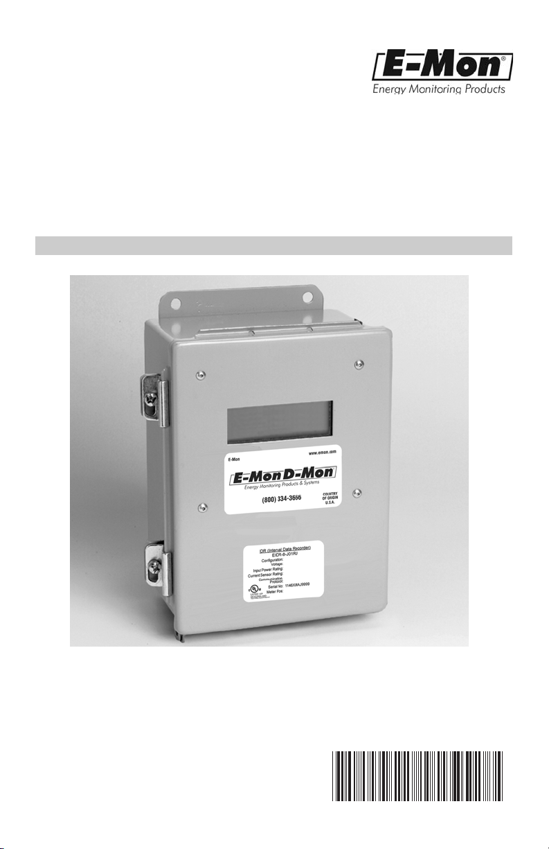
Interval Data
Recorder (IDR)
INSTALLATION INSTRUCTIONS
850 Town Center Drive
E-Mon
Langhorne, PA 19047
(800) 334-3666
www.emon.com
info@emon.com
Page 2

INTERVAL DATA RECORDER (IDR)
Dear Valued Customer,
We are pleased that you chose to buy one of our products, and want you to be just as
pleased with owning it. Before installing your new E-Mon product, please read the
information on the following pages carefully.
We believe that you will find the E-Mon D-Mon meters easy to install and to use for
monitoring and evaluating your electrical usage.
To be sure that you are 100% satisfied with your products, we provide toll-free
technical and sales support Monday through Friday, 8:00 am to 7:30 pm, EST:
(800) 334-3666. You may also reach us via email at info@emon.com.
If you have questions, we can handle them quickly and effectively with a telephone call.
Please let us try to help you BEFORE you remove your meter. And to help us help you,
we ask that you have all relevant information on hand when you call (model or part
numbers, nature of difficulty, etc.)
Be sure to forward this manual to the owner after installation is complete, so that they
may use it as a reference guide when reading the E-Mon D-Mon meter.
Thank you.
62-0394-03 2
Page 3

INTERVAL DATA RECORDER (IDR)
TABLE OF CONTENTS
Section 1.0 Pre-Installation Information 4
Section 2.0 Mechanical Installation 7
Section 3.0 Connecting Meters to the IDR 9
Section 4.0 AC Adapter 10
Section 5.0 IDR Display 13
Section 6.0 Serial Communications (EZ7) 16
Section 7.0 Ethernet Communications 17
Section 8.0 Protocol Definitions 28
Appendix A DIP Switch Settings 29
Appendix B Cable Configuration 30
Appendix C LED Indicator Locations 31
Appendix D IDR Circuit Board Components 32
Appendix E System Wiring Guides 33
Appendix F System Wiring Guides 34
Appendix G Modem System Configuration Diagrams 35
Appendix H Hard Wired System Configuration Diagrams 36
Appendix I Hard Wired System Configuration Diagrams 37
Appendix J IDR Technical Specifications 38
Appendix K Meter Limited Warranty 39
3 62-0394-03
Page 4

INTERVAL DATA RECORDER (IDR)
1.0 PRE-INSTALLATION INFORMATION
The Interval Data Recorder (IDR) is an energy data collection device. Installation must
be performed by qualified personnel only and must be in accordance with local and
national electrical codes. E-Mon and its representatives are not responsible for
damage or injury from improper installation.
The IDR is housed in a JIC Steel Enclosure, where ambient temperatures are between
+32 and +120 degrees Fahrenheit. It is available in 8 and 16 input configurations.
The IDR must be located in an area that is central to the meters connected to it.
IMPORTANT:
All meters can be located up to 500 feet from the IDR.
NOTE: The IDR Modular Jack Model is designed to operate with E-Mon D-Mon
The IDR must be installed in a location according to the following guidelines to ensure
continued safe, trouble-free operation.
• Do not install near sensitive radio communication equipment or receiving antenna
• Do not install near high-energy electrical fields such as those produced by welding
• Always install in an area that is dry, away from any potential liquid or chemical
meters only. Terminal input models can support the monitoring of third-party
metering equipment; contact E-Mon for further information.
systems.
equipment or by high-power electrical motors.
splash hazards. Never install electrical equipment in an area where flammable
chemicals or vapors are present.
62-0394-03 4
Page 5

INTERVAL DATA RECORDER (IDR)
The IDR enclosure door must be kept closed once installed. Exposing the internal
circuits to dust, dirt, fumes or high humidity can damage the IDR.
NOTE: All internal circuits are isolated from the AC line.
IDR-16’s are supplied with an ID letter for each group of 8 inputs to make them
compatible with E-Mon Energy™ software. The available choices are A-B, C-D, E-F, GH, I-J, K-L, M-N, O-P, Q-R, S-T, U-V, W-X and Y-Z. No other combinations are
available. When mixing 8-point and 16-point IDRs together, it may be necessary to
jump a letter in the system. As an example, if you have an 8-point IDR labeled “A”, “B”
and “C”, the 16-point IDR to choose would be the E-F unit.
FCC NOTICE:
This equipment has been tested and found to comply with the limits for a Class B
digital device, pursuant to part 15 of the FCC Rules. These limits are designed to
provide reasonable protection against harmful interference in a residential installation.
This equipment generates, uses and can radiate radio frequency energy and, if not
installed there is no guarantee that interference will not occur in a particular
installation. If this equipment does cause harmful interference to radio or television
reception, which can be determined by turning the equipment off and on, the user is
encouraged to try to correct the interference by one or more of the following measures:
- Reorient or relocate the receiving antenna.
- Increase the separation between the equipment and receiver.
- Connect the equipment into an outlet on a circuit different from that to which the
receiver is connected.
- Consult the dealer or an experienced radio/TV technician for help.
STANDARDS COMPLIANCE:
BACnet MS/TP and IP protocol is BTL listed.
LonWorks TP/FT-10 protocol is LonMark® certified.
5 62-0394-03
Page 6
INTERVAL DATA RECORDER (IDR)
1.0 PRE-INSTALLATION INFORMATION
(CONTINUED)
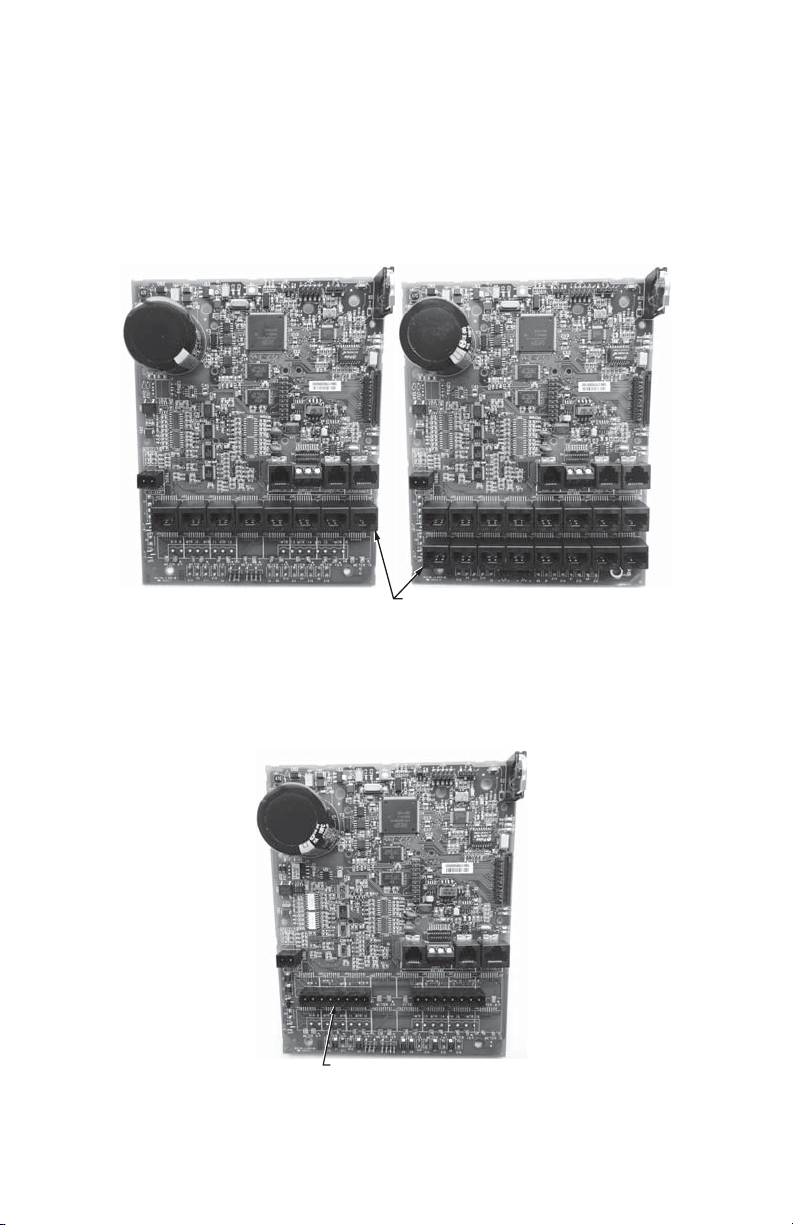
The IDR is available in two configurations.
1. Modular Jacks (IDR-8 and IDR-16): Supplied with all modular jacks for use only
with E-Mon D-Mon meters.
MODULAR JACKS
M33954
Fig. 1. Modular Jacks.
2. Plug-In Screw-Type Connectors (IDR-8): Supplied with all plug-in screw-type
connectors for use with third-party meters (electric, gas, water, etc.) that are provided with a dry contact pulse output.
SCREW-TYPE
CONNECTORS
M33955
Fig. 2. Plug-In Screw-Type Connectors.
62-0394-03 6
Page 7
INTERVAL DATA RECORDER (IDR)
2.0 MECHANICAL INSTALLATION
IMPORTANT:
The internal circuits of the IDR can be damaged by electrostatic discharge.
Before reaching inside the enclosure, discharge yourself by touching an
earth-grounded object.
Accidental discharge of static electricity onto the circuit board can result in:
- Loss of stored data
- A system lock-up
- Permanent damage to the IDR
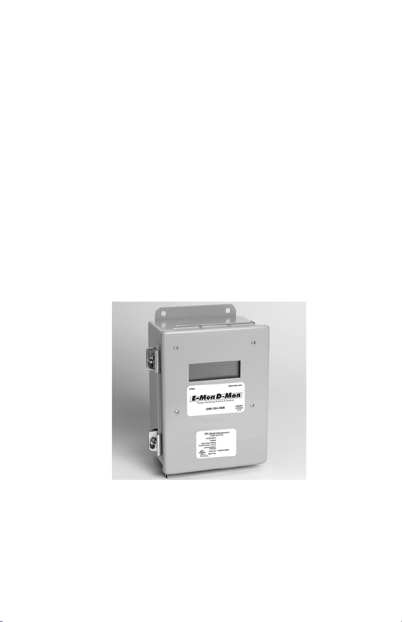
The IDR is available in two types of enclosure systems:
a. Stand-Alone IDR (Standard Configuration).
The stand-alone IDR configuration consists of a single IDR unit. The enclosure should be mounted using the mounting flanges located at the top and
bottom of the enclosure. The enclosure has three available knockouts for
cable entrance/ exit from the IDR.
NEVER ATTEMPT TO DRILL THROUGH THE STEEL ENCLOSURE.
DOING SO MAY PERMANENTLY DAMAGE THE ELECTRONIC CIRCUITRY AND WILL VOID ALL WARRANTIES.
Fig. 3. JIC Steel Enclosure.
b. MMU (Multiple Meter Unit) Configuration.
MMU units containing E-Mon D-Mon meters and IDRs have been pre-wired
by the factory prior to shipment. The meters have been connected to the
IDR. The installer needs to provide 120V power for the IDR unit in the MMU.
See Section 6.0 for communication connections.
7 62-0394-03
Page 8
INTERVAL DATA RECORDER (IDR)
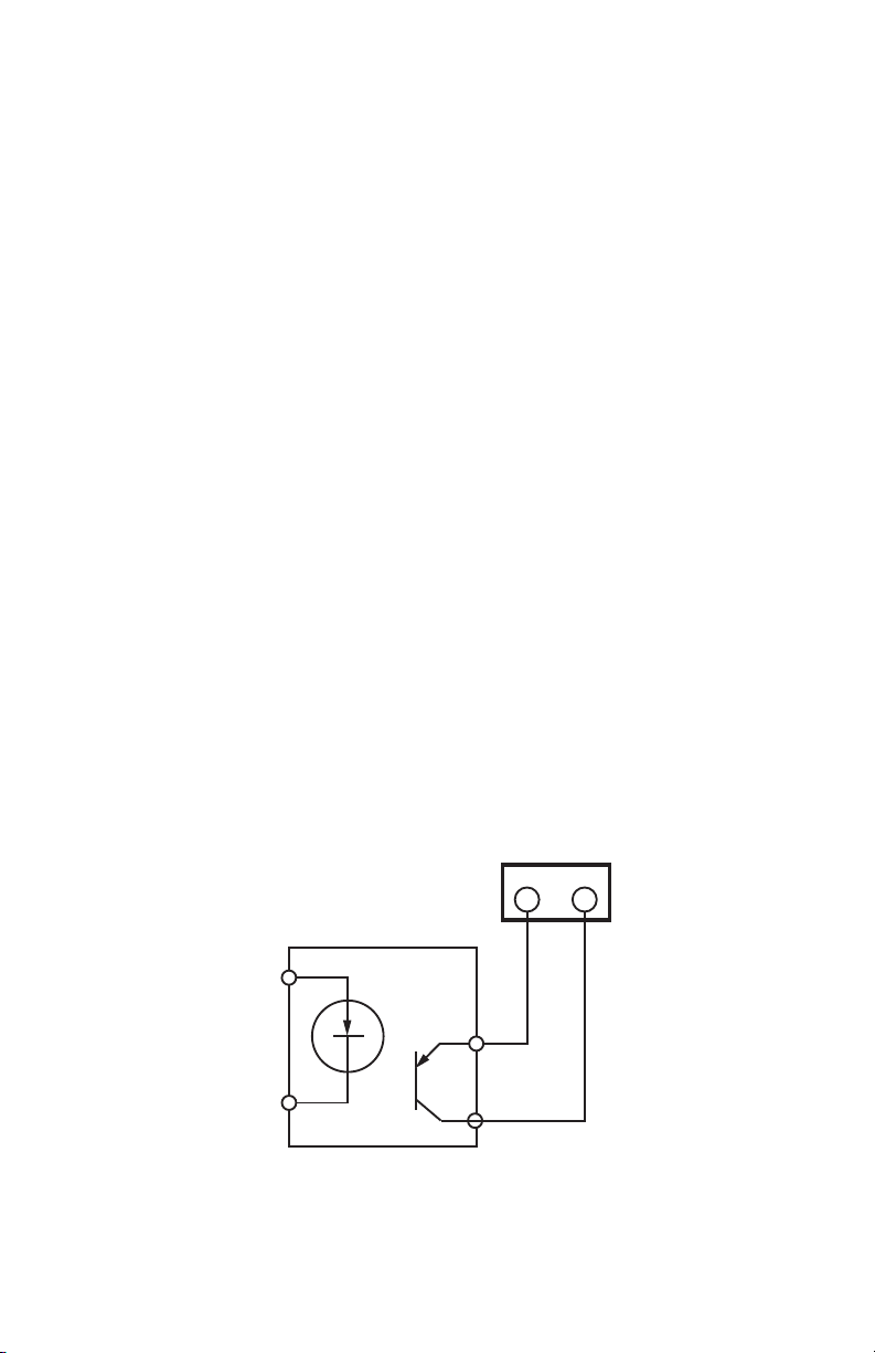
+
–
COM SIG
M33472A
IDR TERMINAL
SOLID
STATE
SWITCH
3.0 CONNECTING METERS TO THE IDR
E-Mon D-Mon Meter Connections
a. Each E-Mon D-Mon meter has two modular jacks located at the top of the
main circuit board. The jack on the left (RJ-45, 8-pin) is used to connect the
meter to the IDR.**
NEVER USE 6-PIN JACKS LABELED “PORT 0” OR “PORT 2” TO CONNECT A METER TO THE IDR.
b. * All E-Mon D-Mon meters must be connected to meter jacks #1-8 using 6-
conductor flat modular cable.**
c. *IDR-16 - If the IDR is an IDR-16, connect the additional meters to Jacks #9-
16 on the circuit board using 6-conductor flat modular cable.**
d. IDR-8s supplied with plug-in screw type connectors can be up to 500 feet
from all meters, and utilize a pair of wires for connecting to the meter pulse
output.**
* See Appendix D for item B&C above.**
** For more information on cable assembly, see Appendix B.**
Pulse Output Meters (IDR-ST Models Only):
a. Each meter is interfaced with the IDR through the plug-in screw type connec-
tors. Any of the connectors may be used with #22-14 AWG conductors.
b. When used with solid-state switches, correct polarity must be observed in
order for that contact to be recognized. The left terminal of the screw-terminal on the IDR must be connected to the plus (+) side of the switch.
c. The meter can be up to 500 feet away from the IDR.
62-0394-03 8
Fig. 4. Meter Connections.
Page 9
INTERVAL DATA RECORDER (IDR)
M33956
POWER INPUT
15-24 VAC
PULSE INPUT
TERMINALS
3.0 CONNECTING METERS TO THE IDR
(CONTINUED)
Third-Party Meter Connections
In order to connect “third-party” meters such as gas, water or utility-type meters, the
IDR must be ordered with the “two-screw” connectors (designated with the suffix ST at
the end of the model number) terminals instead of the modular jacks that are used with
E-Mon D-Mon meters.
The input pulses supplied to the IDR must be non-powered. Pulses can be either
physical (mechanical) contacts or electronic switches. When electronic switches are
used, the left terminal on the IDR is the “+” output and the right is the return from the
switch.
Fig. 5. IDR Terminal Connections.
9 62-0394-03
Page 10

INTERVAL DATA RECORDER (IDR)
4.0 AC ADAPTER
1. The AC adapter’s two-wire cord must be plugged into the IDR at TB20. (The
polarity of these wires does not matter.)
2. Plug the AC adapter into a 120 VAC outlet.
NOTE: The AC adapter is designed to be used with a 120 VAC outlet only.
3. The IDR should now be energized. Perform the visual checks.
Verify the status of the LED indicators on the IDR circuit board. (See Appendix B for
locations.)
1. Power Supply Indicators
- LCD backlite -> if the IDR is powered, the LCD backlite is on.
2. Meter LED Indicators
There are three groups of LEDs located on the main power board:
- Meter status - BEAT, STATUS and LOAD
- RS-485 communication – TX and RX
- Ethernet communication – ACT and LINK
LED CHART
Color Location Definition
BEAT Red D4 Heart beat
STATUS Yellow D5 Firmware status
TX Yellow D1 Transmit
RX Green D2 Receive
ACT
LINK
NOTE: The AC adapter provides an isolated 9 VAC/300 mA power source for the
IDR. Contact E-Mon at (800) 334-3666 if another power supply is to be used.
62-0394-03 10
Green D8 Ethernet communication activity
- blink
Yellow D9 Ethernet connection
- solid LED on
Page 11
INTERVAL DATA RECORDER (IDR)
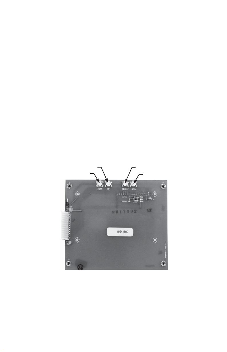
5.0 IDR DISPLAY
The IDR display allows you to manually enter information into the unit. Four push
buttons on the circuit board that is mounted to the door of the meter are utilized for this
function.
The push buttons provide access to entering the time and date, the device ID, and the
IP settings.
Pressing the MENU button allows access to the function menu, up and down buttons
are used to move the pointer.
The SELECT button allows entry to each of the functions. Repeated use of this button
allows the object selected to be modified.
The UP and DOWN buttons are used to modify the object that was selected. Once
changed, the SELECT button is used to move to the next object to be modified. When
completed, press the MENU button to save the setting and exit the function.
The display shows the accumulated meter readings and the load reading of each of
the input channels.
software
Load control is not presently available through the IDR
The input pulse value must be entered through E-Mon Energy
.
.
UP
DOWN
Fig. 6. IDR Display Board.
11 62-0394-03
SELECT
MENU
M33474
Page 12
INTERVAL DATA RECORDER (IDR)
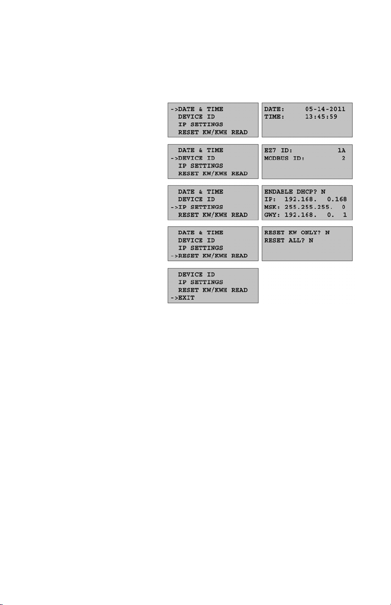
5.0 IDR DISPLAY (CONTINUED)
5.1 Program Mode
62-0394-03 12
Page 13

5.2 Normal Run Modes
1. Energy consumption (kWh)
2. Real-Time Load (kW)
INTERVAL DATA RECORDER (IDR)
13 62-0394-03
Page 14

INTERVAL DATA RECORDER (IDR)
6.0 SERIAL COMMUNICATIONS (EZ7)
a. Hardwired System using the USB Communication Key. (See the hardwired
system configuration diagrams in Appendix F.)
The USB communications key allows you to connect IDRs to a personal
computer that has E-Mon Energy software installed. The computer communicates with the IDRs through the USB key.
The USB key must be located within 15 feet of the host computer.
b. Connecting the USB key to the computer.
The USB key is supplied with:
a. (1) 3 FT USB A to USB B cable
b. (1) 7 FT 4 conductor modular cable with RJ11 4 pin plug
Connect the supplied USB A to USB B cable to the USB Key. Plug the opposite end of the cable into any USB Port of a personal computer or laptop.
Using the CD included with the USB Key, Install (2) drivers to the PC or laptop.
c. Connecting IDRs to the USB Key using the 7 FT modular cable provided with
the USB Key.
As many as 52 IDRs can be connected to the USB Key over a total cable
length of 4000 feet.
62-0394-03 14
Page 15

INTERVAL DATA RECORDER (IDR)
6.0 SERIAL COMMUNICATIONS (EZ7)
(CONTINUED)
Method 1: Modular Plug Method
This method requires using 4 stranded conductors inside a cable that is fitted with an
RJ-11 type plug for 4-conductor modular systems at each end of the cable.
* Do not use any pre-made telephone cables. See Appendix A for correct cable
configuration.
1. Plug the 4-wire RJ-11 cable/plug assembly into either PORT 1 or PORT 2 of the
IDR.
2. The unused RS-485 port is used to connect another cable to the next IDR. This
is called a “daisy-chain” connection. This can be done repeatedly to connect as
many as 52 individual IDRs. NOTE: The total combined cable length must be no
more than 4,000 feet.
3. Each IDR has two LEDs (yellow and green) located directly below the RS-485
jacks. If the system is properly wired, these two LEDs will normally be OFF.
These LEDs will flash when the computer and IDR are communicating.
Method 2: Terminal Block Method
IDRs may also be daisy-chained using a 3-conductor cable. Instead of using the
two modular jacks for the RS-485 daisy chain, you can use Port 1, between the
RJ11 jacks.
1. Daisy-chain the IDRs by connecting:
- All HI terminals together
- All LO terminals together
** This requires putting two wires into each of the 2 terminals.
15 62-0394-03
Page 16

INTERVAL DATA RECORDER (IDR)
6.0 SERIAL COMMUNICATIONS (EZ7)
(CONTINUED)
d. RS-232 Key with Built-In Modem (USBK)
The RS-232 key with built-in modem connects the entire RS-485 network of
IDRs to a telephone line.
** Refer to the previous section, “Connecting IDRs to the RS-232 key using
RS-485.” Connect the RS-485 network via Method 1 or Method 2.
On the back panel of the RS-232 Key/modem, the left jack (RS232) is not
used in most cases since there is no local host computer.
The two jacks at the top center of the rear panel on the RS-232 key/modem
are for connecting to the phone line. Connect one of these two jacks to the
telephone line.
IMPORTANT:
The telephone line should be dedicated exclusively to the automatic meter
reading system. Never connect to a phone line that has other modems or fax
machines connected. If there are telephones connected to this phone line,
the proprietor must be aware that all phones must be on “hook” in order for
the modem to work. A dedicated telephone line is recommended for system
reliability.
e. Baud Rate
The communication baud rate is 9600 baud (factory default).
When using the IDR with a modem, the rate of 9600 should always be
selected.
62-0394-03 16
Page 17

INTERVAL DATA RECORDER (IDR)
M34076
ETHERNET
MODBUS TCP/IP
NETWORK
7.0 ETHERNET COMMUNICATIONS
Ethernet/IP communications connections are provided through an RJ-45
connector(J8) in the lower right corner of the main board. This port can be connected
directly to a network port of a PC using a CAT 5e crossover cable or to an IP router,
hub, or switch using a standard CAT 5e cable.
Two LEDs are provided directly above the connector. The LINK LED is yellow and
when lit, indicates ethernet connectivity. The ACT led is green and when lit, indicates
communication activity.
Communication protocol for the Ethernet/IP port is selectable using the position 2
switch of S2. If position 2 is ON, EZ7 is selected. If position 2 is OFF, Modbus TCP/IP
is selected.
IDR 2500s can be tied into a local Ethernet network (Intranet) or used on the Internet
with a public IP Address. Each device that is connected directly to the ethernet network
requires a unique IP address. The IP address is entered through the pushbuttons
located on the display board. Section 5.0 describes the use of those buttons.
EMS OR CONTROL
UNIT WITH
MODBUS RTU
COMMUNICATION
M34075
Fig. 7. Ethernet Network and EMS or Control Unit.
17 62-0394-03
Page 18

INTERVAL DATA RECORDER (IDR)
8.0 IDR PROTOCOL DEFINITIONS
Modbus Customer Point Map: IDR8 and IDR16
Integer
Address
40001
40003
40005
40007
40009
40011
40013
40015
40017
40019
40021
40023
40025
40027
40029
40031
40065 41065 2 Demand Channel 1Demand Demand
40067 41067 2 Demand Channel 2Demand Demand
Float
Address Registers Description
1
1
1
1
1
1
1
1
1
1
1
1
1
1
1
1
41001
41003
41005
41007
41009
41011
41013
41015
41017
41019
41021
41023
41025
41027
41029
41031
1
1
1
1
1
1
1
1
1
1
1
1
1
1
1
1
2 Usage Channel 1 Pulse Pulse
2 Usage Channel 2 Pulse Pulse
2 Usage Channel 3 Pulse Pulse
2 Usage Channel 4 Pulse Pulse
2 Usage Channel 5 Pulse Pulse
2 Usage Channel 6 Pulse Pulse
2 Usage Channel 7 Pulse Pulse
2 Usage Channel 8 Pulse Pulse
2 Usage Channel 9 Pulse Pulse
2 Usage Channel 10 Pulse Pulse
2 Usage Channel 11 Pulse Pulse
2 Usage Channel 12 Pulse Pulse
2 Usage Channel 13 Pulse Pulse
2 Usage Channel 14 Pulse Pulse
2 Usage Channel 15 Pulse Pulse
2 Usage Channel 16 Pulse Pulse
Integer
Units Float Units IDR
* Pulse Value
* Pulse Value
* Pulse Value
* Pulse Value
* Pulse Value
* Pulse Value
* Pulse Value
* Pulse Value
* Pulse Value
* Pulse Value
* Pulse Value
* Pulse Value
* Pulse Value
* Pulse Value
* Pulse Value
* Pulse Value
* Pulse Value
* Pulse Value
R/W
R/W
R/W
R/W
R/W
R/W
R/W
R/W
R/W
R/W
R/W
R/W
R/W
R/W
R/W
R/W
R
R
62-0394-03 18
Page 19

INTERVAL DATA RECORDER (IDR)
Modbus Customer Point Map: IDR8 and IDR16
Integer
Address
Float
Address Registers Description
Integer
Units Float Units IDR
40069 41069 2 Demand Channel 3Demand Demand
* Pulse Value
40071 41071 2 Demand Channel 4Demand Demand
* Pulse Value
40073 41073 2 Demand Channel 5Demand Demand
* Pulse Value
40075 41075 2 Demand Channel 6Demand Demand
* Pulse Value
40077 41077 2 Demand Channel 7Demand Demand
* Pulse Value
40079 41079 2 Demand Channel 8Demand Demand
* Pulse Value
40081 41081 2 Demand Channel 9Demand Demand
* Pulse Value
40083 41083 2 Demand Channel 10Demand Demand
* Pulse Value
40085 41085 2 Demand Channel 11Demand Demand
* Pulse Value
40087 41087 2 Demand Channel 12Demand Demand
* Pulse Value
40089 41089 2 Demand Channel 13Demand Demand
* Pulse Value
40091 41091 2 Demand Channel 14Demand Demand
* Pulse Value
40093 41093 2 Demand Channel 15Demand Demand
* Pulse Value
40095 41095 2 Demand Channel 16Demand Demand
* Pulse Value
R
R
R
R
R
R
R
R
R
R
R
R
R
R
Modbus Customer Point Map: IDR8 and IDR16
Address Registers Format Description IDR
1
44001
44007
45501
46025
6 Custom Interval Day Block R/W
2
1 per interval Integer Interval Data R
3
2 per day Custom Interval Data Headers R
4
8 Custom RTC Date/Time R/W
19 62-0394-03
Page 20

INTERVAL DATA RECORDER (IDR)
5
46049
8 Custom EZ7 ID, Modbus ID, Serial Number R/W
46057 8 Custom Recorder Info., Demand Interval R/W
46513 8 Custom Flags L1: Power Failure, Battery R
46521 8 Custom Flags L2: Power Failure Date R
1. To set the interval data day block, set multiple points at 44001 for 6 points with data
set to 0C0I 0000 MMDD YYYY 0000 0000. 0C = Channel, 0I = Interval (0F = 15
minute intervals, 05 = 5 minute intervals)
2. Each register represents a 15 or 5 minute pulse value based on the interval day
block. 96 registers max with 15 minute intervals. 288 registers max with 5 minute
intervals. The first interval data register 44007 represents the pulse count for the first
15 or 5 minute interval beginning at midnight.
3. The interval data headers represent days with available interval data. Each day
represents 2 registers. Format: MMDD YYYY.
4. To set the date and time, set multiple points at 46025 for 4 points with data set to
HHMM SSDW MMDD YYYY (DW=day of week)
5. To change the Modbus ID, set single point at 46050 with data set to new Modbus ID
(e.g. 1 to 247). Jumper J6 must be closed.
With an IDR16 each channel 1 through 16 represents the IDR16 meter jack inputs 1
through 16.
With an IDR8 each channel 1 through 8 represents the IDR8 meter jack inputs 1
through 8.
BACnet Object Descriptors Customer: IDR8 and IDR16
Instance
ID BACnet Object
1
1
1
2
1
3
1
4
1
5
1
6
1
7
Analog Input Usage Channel 1 Pulse * Pulse Value Present
Analog Input Usage Channel 2 Pulse * Pulse Value Present
Analog Input Usage Channel 3 Pulse * Pulse Value Present
Analog Input Usage Channel 4 Pulse * Pulse Value Present
Analog Input Usage Channel 5 Pulse * Pulse Value Present
Analog Input Usage Channel 6 Pulse * Pulse Value Present
Analog Input Usage Channel 7 Pulse * Pulse Value Present
Description
Units
BACnet
Property IDR
R
Val ue
R
Val ue
R
Val ue
R
Val ue
R
Val ue
R
Val ue
R
Val ue
62-0394-03 20
Page 21

INTERVAL DATA RECORDER (IDR)
BACnet Object Descriptors Customer: IDR8 and IDR16
Instance
Description
ID BACnet Object
8
9
10
11
12
13
14
15
16
1
1
1
1
1
1
1
1
1
Analog Input Usage Channel 8 Pulse * Pulse Value Present
Analog Input Usage Channel 9 Pulse * Pulse Value Present
Analog Input Usage Channel 10 Pulse * Pulse Value Present
Analog Input Usage Channel 11 Pulse * Pulse Value Present
Analog Input Usage Channel 12 Pulse * Pulse Value Present
Analog Input Usage Channel 13 Pulse * Pulse Value Present
Analog Input Usage Channel 14 Pulse * Pulse Value Present
Analog Input Usage Channel 15 Pulse * Pulse Value Present
Analog Input Usage Channel 16 Pulse * Pulse Value Present
17 Analog Input Demand Channel 1 Demand
* Pulse Value
18 Analog Input Demand Channel 2 Demand
* Pulse Value
19 Analog Input Demand Channel 3 Demand
* Pulse Value
20 Analog Input Demand Channel 4 Demand
* Pulse Value
21 Analog Input Demand Channel 5 Demand
* Pulse Value
22 Analog Input Demand Channel 6 Demand
* Pulse Value
23 Analog Input Demand Channel 7 Demand
* Pulse Value
24 Analog Input Demand Channel 8 Demand
* Pulse Value
25 Analog Input Demand Channel 9 Demand
* Pulse Value
26 Analog Input Demand Channel 10Demand
* Pulse Value
Units
BACnet
Property IDR
R
Val ue
R
Val ue
R
Val ue
R
Val ue
R
Val ue
R
Val ue
R
Val ue
R
Val ue
R
Val ue
Present
R
Val ue
Present
R
Val ue
Present
R
Val ue
Present
R
Val ue
Present
R
Val ue
Present
R
Val ue
Present
R
Val ue
Present
R
Val ue
Present
R
Val ue
Present
R
Val ue
21 62-0394-03
Page 22

INTERVAL DATA RECORDER (IDR)
BACnet Object Descriptors Customer: IDR8 and IDR16
Instance
ID BACnet Object
27 Analog Input Demand Channel 11Demand
28 Analog Input Demand Channel 12Demand
29 Analog Input Demand Channel 13Demand
30 Analog Input Demand Channel 14Demand
31 Analog Input Demand Channel 15Demand
32 Analog Input Demand Channel 16Demand
Description
Units
* Pulse Value
* Pulse Value
* Pulse Value
* Pulse Value
* Pulse Value
* Pulse Value
BACnet
Property IDR
Present
Val ue
Present
Val ue
Present
Val ue
Present
Val ue
Present
Val ue
Present
Val ue
BACnet
Instance ID
Object BACnet Property IDR
BACnet Device ID Device Object identifier R
BACnet Device ID Device Object name R
BACnet Device ID Device Object type R
BACnet Device ID Device System status R/W
BACnet Device ID Device Vendor name R
BACnet Device ID Device Vendor Identifier R
BACnet Device ID Device Model name R
BACnet Device ID Device Firmware revision R
BACnet Device ID Device Application software version R
BACnet Device ID Device Location R/W
BACnet Device ID Device Description R/W
BACnet Device ID Device Protocol version R
BACnet Device ID Device Protocol services supported R
BACnet Device ID Device Protocol object types supported R
BACnet Device ID Device Protocol revision R
BACnet Device ID Device Object list R
BACnet Device ID Device Max APDU length supported R
BACnet Device ID Device Segmentation supported R
BACnet Device ID Device Local time R
BACnet Device ID Device Local date R
R
R
R
R
R
R
62-0394-03 22
Page 23

INTERVAL DATA RECORDER (IDR)
BACnet
Instance ID
Object BACnet Property IDR
BACnet Device ID Device APDU time-out R/W
BACnet Device ID Device Number of APDU retries R/W
With an IDR16 each channel 1 through 16 represents the IDR16 meter jack inputs 1
through 16.
With an IDR8 each channel 1 through 8 represents the IDR8 meter jack inputs 1
through 8.
23 62-0394-03
Page 24

INTERVAL DATA RECORDER (IDR)
PIC STATEMENT
BACNET PROTOCOL IMPLEMENTATION CONFORMANCE STATEMENT
Date October 2013
Vendor Name: E-Mon
Vendor ID: 482
Product Name: CL3200, CL3400, CL5000, IDR and Din-Mon™ Meters
Product Model
Numbers:
Product
Description
BACnet Standardized Device Profile (Annex L):
X BACnet Smart Sensor (B-SS)
BACnet Interoperability Building Blocks Supported (Annex K):
X K.1.2 BIBB - Data Sharing - ReadProperty-B (DS-RP-B)
X K.1.4 BIBB - Data Sharing - ReadPropertyMultiple-B (DS-RPM-B)
X K.5.2 BIBB - Device Management - Dynamic Device Binding-B (DM-DDB-B)
X K.5.4 BIBB - Device Management - Dynamic Object Binding-B (DM-DOB-B)
X K.5.12 BIBB - Device Management - TimeSynchronization-B (DM-TS-B)
Segmentation Capability:
None
E32-208100-RBACKIT, E34-480200-R05KIT,
E50-480200-R03KIT, EIDR-8-R05RJ
This product will provide bi-directional communication between E-Mon
BACnet MS/TP meters, BACnet IP meters, and a BACnet system.
Standard Object Types Supported
X Device Object
X Analog Input
For all these properties, the following apply:
1. Does not support BACnet CreateObject
2. Does not support BACnet DeleteObject
3. No additional writable properties exist
4. No proprietary properties exist
5. No range restrictions exist
Data Link Layer Options:
X MS/TP master (Clause 9), baud rate(s): 9.6k, 19.2k, 38.4k, 76.8k bps
X BACnet IP, (Annex J): Din-Mon™ CL3200 does not support BACnet IP
Device Address Binding:
Not supported
Character Sets Supported:
X ANSI X3.4
62-0394-03 24
Page 25

Network Variable
Name
nvoUsageCh01
nvoUsageCh02
nvoUsageCh03
nvoUsageCh04
nvoUsageCh05
nvoUsageCh06
nvoUsageCh07
nvoUsageCh08
nvoUsageCh09
nvoUsageCh10
nvoUsageCh11
nvoUsageCh12
nvoUsageCh13
nvoUsageCh14
nvoUsageCh15
nvoUsageCh16
nvoUsageCh17
nvoUsageCh18
INTERVAL DATA RECORDER (IDR)
E-Mon D-Mon LonWorks Point Map: IDR8 and IDR16
Func-
tion
Block
Index SNVT Type Description Units IDR
1
1 SNVT_count_f Usage
1
2 SNVT_count_f Usage
1
3 SNVT_count_f Usage
1
4 SNVT_count_f Usage
1
5 SNVT_count_f Usage
1
6 SNVT_count_f Usage
1
7 SNVT_count_f Usage
1
8 SNVT_count_f Usage
1
9 SNVT_count_f Usage
1
10 SNVT_count_f Usage
1
11 SNVT_count_f Usage
1
12 SNVT_count_f Usage
1
13 SNVT_count_f Usage
1
14 SNVT_count_f Usage
1
15 SNVT_count_f Usage
1
16 SNVT_count_f Usage
1
17 SNVT_count_f Usage
1
18 SNVT_count_f Usage
Channel 1
Channel 2
Channel 3
Channel 4
Channel 5
Channel 6
Channel 7
Channel 8
Channel 9
Channel 10
Channel 11
Channel 12
Channel 13
Channel 14
Channel 15
Channel 16
Channel 17
Channel 18
Pulse *
Pulse Value
Pulse *
Pulse Value
Pulse *
Pulse Value
Pulse *
Pulse Value
Pulse *
Pulse Value
Pulse *
Pulse Value
Pulse *
Pulse Value
Pulse *
Pulse Value
Pulse *
Pulse Value
Pulse *
Pulse Value
Pulse *
Pulse Value
Pulse *
Pulse Value
Pulse *
Pulse Value
Pulse *
Pulse Value
Pulse *
Pulse Value
Pulse *
Pulse Value
Pulse *
Pulse Value
Pulse *
Pulse Value
R
R
R
R
R
R
R
R
R
R
R
R
R
R
R
R
R
R
25 62-0394-03
Page 26

INTERVAL DATA RECORDER (IDR)
E-Mon D-Mon LonWorks Point Map: IDR8 and IDR16
Func-
tion
Network Variable
Name
nvoUsageCh19
nvoUsageCh20
nvoUsageCh21
nvoUsageCh22
nvoUsageCh23
nvoUsageCh24
nvoUsageCh25
nvoUsageCh26
nvoUsageCh27
nvoUsageCh28
nvoUsageCh29
nvoUsageCh30
nvoUsageCh31
nvoUsageCh32
Block
Index SNVT Type Description Units IDR
1
19 SNVT_count_f Usage
Channel 19
1
20 SNVT_count_f Usage
Channel 20
1
21 SNVT_count_f Usage
Channel 21
1
22 SNVT_count_f Usage
Channel 22
1
23 SNVT_count_f Usage
Channel 23
1
24 SNVT_count_f Usage
Channel 24
1
25 SNVT_count_f Usage
Channel 25
1
26 SNVT_count_f Usage
Channel 26
1
27 SNVT_count_f Usage
Channel 27
1
28 SNVT_count_f Usage
Channel 28
1
29 SNVT_count_f Usage
Channel 29
1
30 SNVT_count_f Usage
Channel 30
1
31 SNVT_count_f Usage
Channel 31
1
32 SNVT_count_f Usage
Channel 32
nvoDemandCh01 33 SNVT_count_f Demand
Channel 1
nvoDemandCh02 34 SNVT_count_f Demand
Channel 2
nvoDemandCh03 35 SNVT_count_f Demand
Channel 3
nvoDemandCh04 36 SNVT_count_f Demand
Channel 4
Pulse *
Pulse Value
Pulse *
Pulse Value
Pulse *
Pulse Value
Pulse *
Pulse Value
Pulse *
Pulse Value
Pulse *
Pulse Value
Pulse *
Pulse Value
Pulse *
Pulse Value
Pulse *
Pulse Value
Pulse *
Pulse Value
Pulse *
Pulse Value
Pulse *
Pulse Value
Pulse *
Pulse Value
Pulse *
Pulse Value
Demand *
Pulse Value
Demand *
Pulse Value
Demand *
Pulse Value
Demand *
Pulse Value
R
R
R
R
R
R
R
R
R
R
R
R
R
R
R
R
R
R
62-0394-03 26
Page 27

INTERVAL DATA RECORDER (IDR)
E-Mon D-Mon LonWorks Point Map: IDR8 and IDR16
Func-
tion
Network Variable
Name
Block
Index SNVT Type Description Units IDR
nvoDemandCh05 37 SNVT_count_f Demand
Channel 5
nvoDemandCh06 38 SNVT_count_f Demand
Channel 6
nvoDemandCh07 39 SNVT_count_f Demand
Channel 7
nvoDemandCh08 40 SNVT_count_f Demand
Channel 8
nvoDemandCh09 41 SNVT_count_f Demand
Channel 9
nvoDemandCh10 42 SNVT_count_f Demand
Channel 10
nvoDemandCh11 43 SNVT_count_f Demand
Channel 11
nvoDemandCh12 44 SNVT_count_f Demand
Channel 12
nvoDemandCh13 45 SNVT_count_f Demand
Channel 13
nvoDemandCh14 46 SNVT_count_f Demand
Channel 14
nvoDemandCh15 47 SNVT_count_f Demand
Channel 15
nvoDemandCh16 48 SNVT_count_f Demand
Channel 16
nvoDemandCh17 49 SNVT_count_f Demand
Channel 17
nvoDemandCh18 50 SNVT_count_f Demand
Channel 18
nvoDemandCh19 51 SNVT_count_f Demand
Channel 19
nvoDemandCh20 52 SNVT_count_f Demand
Channel 20
nvoDemandCh21 53 SNVT_count_f Demand
Channel 21
nvoDemandCh22 54 SNVT_count_f Demand
Channel 22
Demand *
Pulse Value
Demand *
Pulse Value
Demand *
Pulse Value
Demand *
Pulse Value
Demand *
Pulse Value
Demand *
Pulse Value
Demand *
Pulse Value
Demand *
Pulse Value
Demand *
Pulse Value
Demand *
Pulse Value
Demand *
Pulse Value
Demand *
Pulse Value
Demand *
Pulse Value
Demand *
Pulse Value
Demand *
Pulse Value
Demand *
Pulse Value
Demand *
Pulse Value
Demand *
Pulse Value
R
R
R
R
R
R
R
R
R
R
R
R
R
R
R
R
R
R
27 62-0394-03
Page 28

INTERVAL DATA RECORDER (IDR)
E-Mon D-Mon LonWorks Point Map: IDR8 and IDR16
Func-
tion
Network Variable
Name
Block
Index SNVT Type Description Units IDR
nvoDemandCh23 55 SNVT_count_f Demand
Channel 23
nvoDemandCh24 56 SNVT_count_f Demand
Channel 24
nvoDemandCh25 57 SNVT_count_f Demand
Channel 25
nvoDemandCh26 58 SNVT_count_f Demand
Channel 26
nvoDemandCh27 59 SNVT_count_f Demand
Channel 27
nvoDemandCh28 60 SNVT_count_f Demand
Channel 28
nvoDemandCh29 61 SNVT_count_f Demand
Channel 29
nvoDemandCh30 62 SNVT_count_f Demand
Channel 30
nvoDemandCh31 63 SNVT_count_f Demand
Channel 31
nvoDemandCh32 64 SNVT_count_f Demand
Channel 32
1
nviResetUsageCh
65 SNVT_count Reset
Usage
Channel
nvoRTC_DateTime 66 SNVT_time_stamp RTC Date,
Time Read
2
nviRTC_DateTime
nvoIntervalData
66 SNVT_time_stamp RTC Date,
3
67 SNVT_reg_val_ts Interval
Time Set
Data Pulse
Read
3
nviIntDataTime
67 SNVT_time_stamp Interval
Date, Time
Set
3
nviIntDataChan
67 SNVT_count Interval
Data
Channel Set
Demand *
R
Pulse Value
Demand *
R
Pulse Value
Demand *
R
Pulse Value
Demand *
R
Pulse Value
Demand *
R
Pulse Value
Demand *
R
Pulse Value
Demand *
R
Pulse Value
Demand *
R
Pulse Value
Demand *
R
Pulse Value
Demand *
R
Pulse Value
Integer
R/W
Channel
Date, Time R
Date, Time R/W
Integer
R
Pulses, Date,
Time
Date, Time R/W
Integer
R/W
Channel
62-0394-03 28
Page 29

INTERVAL DATA RECORDER (IDR)
E-Mon D-Mon LonWorks Point Map: IDR8 and IDR16
Func-
tion
Network Variable
Name
nviIntDataPeriod
Block
Index SNVT Type Description Units IDR
3
67 SNVT_count Interval
Minutes R/W
Data
Window Set
nvoStatus
nviRequest
4
4
0 SNVT_obj_status Function
Block Status
0 SNVT_obj_request Function
Block
Request
Function
Block Status
Function
Block
Enable/
R
R/W
Disable
nvoFileDirectory 0 SNVT_address File
Directory
Config File
Directory
R
1. To clear all usage channels, select reset kW/kWh on the display menu of the IDR.
Jumper J6 must be closed. To clear individual channels, set nviResetUsageCh to the
desired channel. For example, set nviResetUsageCh to 1 to reset nvoUsageCh01.
2. To set the real time clock, set nviRTC_DateTime to the desired date and time.
3. NvoIntervalData will display the number of pulses for the selected interval period
and channel. For example, set nviIntDataTime to 6/1/2012 13:15:00 to read the
number of pulses from 13:15:00 to 13:29:59. The second status bit value will be 0 if
no error has occurred. The interval data period window can be set to read 15 or 5
minutes using the nviIntDataPeriod. This value will not change the default interval
data period value of 15 minutes. NviIntDataChan will select the usage channel. For
example, set nviIntDataChan to 1 to read the interval data for nvoUsageCh01.
4. NviRequest commands can disable or enable functional blocks. Any changes will
be saved even after powered down. Set nviRequest to 0,RQ_DISABLE to disable all
functional blocks. Set nviRequest to 0,RQ_ENABLE to enable all function blocks. Set
nviRequest to 1,RQ_DISABLE to disable only functional block 1. The first value of
nvoStatus is the functional block, and the 3
rd
bit in the bit array is 1 when disabled.
With an IDR16 each channel 1 through 16 represents the IDR16 meter jack inputs 1
through 16.
With an IDR8 each channel 1 through 8 represents the IDR8 meter jack inputs 1
through 8.
29 62-0394-03
Page 30

INTERVAL DATA RECORDER (IDR)
M33277A
3 4 BAUD RATE
ON ON 9600
OFF ON 19200
ON OFF 38400
OFF OFF 76800
Appendix A - DIP Switch Settings
The 10-position DIP Switch is used to configure:
• RS-485 Communication protocol (pos 1)
• Ethernet Communication protocol (pos 2)
• RS-485 Baud rate (pos 3 & 4)
• Single channel input mode for RJ45 style connector and ST (screw terminal); dualchannel only available on RJ45. (pos 5)
• Spare Pos 7 & 8
• RS-485 Bias (pos 9 & 10); only one device on the network needs to have biasing.
The communication baud rate is selected by means of a DIP Switch on the circuit
board. There are four (4) selections: 9600 (factory default), 19.2k, 38.4k, and 76.8k
bps; higher baud rate would reduce cabling length. When connecting the device to an
RS-485 network needing the use of biasing the RS-485 line, turn on DIP Switch pos 9
and pos 10. After changing the DIP switch selections (1.8), restart the device for the
new settings to take effect (9&10 for BIAS doesn’t require CPU restart).
Fig. 8. DIP Switch Baud Rates.
62-0394-03 30
Page 31

INTERVAL DATA RECORDER (IDR)
M33476
BLACK
RED
GREEN
YELLOW
BLACK
RED
GREEN
YELLOW
Appendix B - Cable Configurations
1. Four-Conductor Cables (IDR RS-485 Communication)
2. Six-Conductor Cables (Meters #1-#8, optional #9-#16)
WHITE
BLACK
RED
GREEN
BLUE
YELLOW
Fig. 9. Cable Configurations
31 62-0394-03
RED
GREEN
YELLOW
M33477
BLUE
WHITE
BLACK
Page 32

INTERVAL DATA RECORDER (IDR)
Appendix C - LED Indicator Locations
CPU
INDICATOR
LEDS
COMMUNICATION
INDICATOR
LEDS
FOR ETHERNET
COMMUNICATIONS
M34077
Fig. 10. LED Indicator Locations
62-0394-03 32
Page 33

INTERVAL DATA RECORDER (IDR)
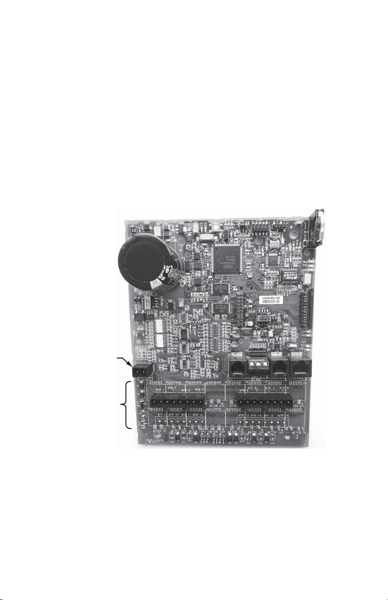
M33958
BATTERY
FOR RTC
COMMUNICATION
PORTS
CPU RESET
METER INPUTS
EXTERNAL
POWER IN
Appendix D - IDR Circuit Board Components
Fig. 11. IDR Modular Jack.
33 62-0394-03
Page 34

INTERVAL DATA RECORDER (IDR)
Appendix E - System Wiring Guides
PC
CONNECTS VIA
USB PORT ON PC
3 FT USB A TO USB B CABLE
USB
KEY*
FLAT MODULAR CABLE
UP TO 4000 FEET TOTAL
RJ-11
4-CONDUCTOR
DAISY-CHAIN
IDR A
6-COND.
RJ-45
AC ADAPTER
RJ-11
~
UP TO 52 IDRS
AC ADAPTER
NOTE: METERS 1-8 MUST BE INSTALLED WITHIN 500 FEET OF IDR.
CONNECTION CABLE TYPE CONNECTOR
IDR TO E-MON D-MON METERS 1-8 6-COND. 22-26 AWG RJ-45
(PINS 1 & 8 NOT USED)
IDR TO IDR 4-COND. 26 AWG RJ-11
IDR TO USB KEY 4-COND. 26 AWG RJ-11
USB KEY TO COMPUTER** 3 FT USB A to USB B Cable RJ-45/DTE
IDR TO PULSE METER 2-COND. 14-22 AWG
** SUPPLIED BY E-MON
NOTE: INTERIOR INTERCONNECTING COMMUNICATIONS ARE SUPPLIED WITH THE
PRE-WIRED MMU-TYPE METERING CABINETS.
NOTE: WHEN CONSTRUCTING FIELD-INSTALLED CABLES, MODULAR CABLES MUST BE
MADE SO THAT THE INDIVIDUAL WIRES GO THROUGH ON THE SAME PIN NUMBER.
* CONTACT E-MON FOR USB-ONLY CONNECTION.
IDR Z
~
6-COND.
RJ-45
6-COND.
RJ-45
(UP TO 8
METERS)
(UP TO 8
METERS)
M34078B
62-0394-03 34
Page 35

INTERVAL DATA RECORDER (IDR)
NOTE: METERS 1-8 MUST BE INSTALLED WITHIN 500 FEET OF IDR.
(UP TO 16 METERS)
(UP TO
16 METERS)
~
~
4-CONDUCTOR
FLAT MODULAR CABLE
UP TO 4000 FEET TOTAL
DAISY-CHAIN
UP TO 26 IDR-16S PER
CHANNEL
USB
KEY*
CONNECTS VIA
USB PORT ON PC
RJ-11
6-COND.
RJ-45
RJ-11
6-COND.
RJ-45
6-COND.
RJ-45
IDR A-B
IDR Y-Z
CONNECTION CABLE TYPE CONNECTOR
IDR TO E-MON D-MON METERS 1- 16 6-COND. 22-26 AWG RJ-45
(PINS 1 & 8 NOT USED)
IDR TO USB KEY 4-COND. 26 AWG RJ-11
IDR TO RS-232 KEY 2000 4-COND. 26 AWG RJ-11
RS-232 KEY 2000 TO COMPUTER** 8-COND. 22-26 AWG RJ-45/DTE
FLAT MODULAR CABLE
IDR TO PULSE METER 2-COND. 14-22 AWG
** SUPPLIED BY E-MON
NOTE: INTERIOR INTERCONNECTING COMMUNICATIONS ARE SUPPLIED
WITH THE PRE-WIRED MMU-TYPE METERING CABINETS.
NOTE: WHEN CONSTRUCTING FIELD-INSTALLED CABLES, MODULAR CABLES
MUST BE MADE SO THAT THE INDIVIDUAL WIRES GO THROUGH ON
THE SAME PIN NUMBER.
* CONTACT E-MON FOR USB-ONLY CONNECTION.
3RD
PARTY
METER
3RD
PARTY
METER
3RD
PARTY
METER
PAIR OF WIRES
(#22-#14 AWG)
PC
AC ADAPTER
AC ADAPTER
M34079A
Appendix F - System Wiring Guides
35 62-0394-03
Page 36

INTERVAL DATA RECORDER (IDR)
NOTES: METERS 1-8 (OR 1-16) MUST BE INSTALLED WITHIN 500 FEET OF IDR.
METERS 1-8 (OR 1-16) USE 6-CONDUCTOR CABLE.
RS-232 SERIAL PORT
COM1 THROUGH
COM4 MAX. 15'
LOCAL
MODEM
TELEPHONE
LINK
UP TO 26
IDR-16S
PER CHANNEL
IDR A-B
IDR Y-Z
IDR A-B
IDR Y-Z
UP TO 16 METERS
UP TO 16 METERS
UP TO 16 METERS
IDR-16, USING E-MON D-MON METERS:
CHANNEL 2
~
~
~
~
CHANNEL 1
AC ADAPTER
E-MON
EKM-T
UP TO 16 METERS
CHANNEL 3
~
~
RS-232 SERIAL PORT
COM1 THROUGH
COM4 MAX. 15'
LOCAL
MODEM
TELEPHONE
LINK
UP TO 52
IDRS PER
CHANNEL
UP TO 52
IDRS PER
CHANNEL
IDR A
IDR A
IDR Z
UP TO 8 METERS
UP TO 8 METERS
UP TO 8 METERS
IDR-8, USING E-MON D-MON
®
METERS:
CHANNEL 2
~
~
~
~
CHANNEL 1
UP TO 4000
FEET TOTAL
AC ADAPTER
UP TO 8 METERS
CHANNEL 3
~
~
E-MON
EKM-T
UP TO 4000
FEET TOTAL
UP TO 4000
FEET TOTAL
UP TO 4000
FEET TOTAL
UP TO 26
IDR-16S
PER CHANNEL
PC
PC
IDR Z
AC ADAPTER
AC ADAPTER
AC ADAPTER
AC ADAPTER
AC ADAPTER
AC ADAPTER
AC ADAPTER
AC ADAPTER
M33740A
Appendix G - Modem System Configuration Diagrams
62-0394-03 36
Page 37

INTERVAL DATA RECORDER (IDR)
Appendix H - Hard Wired System Configuration
Diagrams
IDR-8, USING E-MON D-MON® METERS:
AC ADAPTER
UP TO 4000
FEET TOTAL
PC
CABLE
SUPPLIED
BY E-MON
15 FEET MAX.
NOTES: METERS 1-16 MUST BE INSTALLED WITHIN 500 FEET OF IDR.
METERS 1-16 USE 6-CONDUCTOR CABLE
RS-232
SERIAL PORT
COM1-COM4
AC ADAPTER
CHANNEL 1
RS-232
KEY*
CHANNEL 3
UP TO
52 IDRS
AC
ADAPTER
AC ADAPTER
UP TO 4000
FEET TOTAL
UP TO
52 IDRS
AC ADAPTER
IDR
~
~
IDR
IDR
~
~
~
~
IDR
UP TO 8 METERS
UP TO 8 METERS
CHANNEL 2
UP TO 8 METERS
UP TO 8 METERS
M33741A
37 62-0394-03
Page 38

INTERVAL DATA RECORDER (IDR)
IDR-16, USING OTHER UTILITY-TYPE METERS
(GAS, WATER, ETC.)
UP TO 16 METERS
UP TO 16 METERS
CHANNEL 2
~
~
~
~
CHANNEL 1
CHANNEL 3
AC ADAPTER
UP TO 16 METERS
UP TO 16 METERS
IDR-16, USING E-MON D-MON
®
METERS
UP TO 16 METERS
UP TO 16 METERS
CHANNEL 2
~
~
CHANNEL 1
CHANNEL 3
UP TO 26
IDR-16S
NOTES: METERS 1-16 MUST BE INSTALLED WITHIN 500 FEET OF IDR.
METERS 1-16 USE 6-CONDUCTOR CABLE.
AC ADAPTER
RS-232
KEY*
6 FOOT CABLE
PROVIDED BY
E-MON (15
FEET MAX)
RS-232
SERIAL PORT
COM1-COM4
UP TO 16 METERS
UP TO 16 METERS
AC ADAPTER
IDR
IDR
IDR
IDR
IDR
IDR
IDR
IDR
M33742
PC
UP TO 4000
FEET TOTAL
UP TO 4000
FEET TOTAL
UP TO 26
IDR-16S
PC
6 FOOT CABLE
PROVIDED BY
E-MON (15
FEET MAX)
RS-232
SERIAL PORT
COM1-COM4
RS-232
KEY*
UP TO 4000
FEET TOTAL
UP TO 4000
FEET TOTAL
AC ADAPTER
AC ADAPTER
UP TO 26
IDR-16S
UP TO 26
IDR-16S
AC ADAPTER
AC ADAPTER
NOTES: METERS MUST BE INSTALLED WITHIN 500 FEET OF IDR.
METER CONNECTED WITH A PAIR OF #22-#14 AWG CONDUCTORS.
AC ADAPTER
AC ADAPTER
AC ADAPTER
~
~
Appendix I - Hard Wired System Configuration
Diagrams (Continued)
62-0394-03 38
Page 39

INTERVAL DATA RECORDER (IDR)
Appendix J - IDR Technical Specifications
Enclosure: Lockable steel JIC box NEMA 12
Dimensions: 9.5” H x 6.75” W x 3.875” D
Knockouts: Three (3) on bottom of enclosure (3/4” Cond.)
Power Supply: Powered by 120 VAC adapter
Back Up: Lithium Power Cell CR2032 (10 year lifetime)
LED Indicators BEAT, STATUS, TX, RX, ACT, LINK
Inputs: IDR-8: Eight (8) eight-pin modular ports
or Eight (8) 2-screw plug-in terminals
IDR-16: Sixteen (16) eight-pin modular ports
Max Pulse Input: <600 pulses per minute (50% duty cycle)
Data Storage: 36 days @ 5-minute sampling intervals 72 days @ 15-
minute sampling intervals
Interface with: E-Mon D-Mon submeters, electric utility meters, third-
party submeters, gas meters, water meters, BTU meters,
and any meter equipped with a contact pulse output
(using available 2-screw terminals.)
Power Consumption: 2 watts maximum, 1.2 watts typical
Processor: 32-bit;12 MHz main clock, 60 MHz internal
Real-Time Clock: 100-year clock/calendar automatically makes changes to
standard/daylight savings time
Communications: Serial, RS-485, 2-wire, half duplex. Optically isolated from
all other circuits. 9600 bps standard.
39 62-0394-03
Page 40

INTERVAL DATA RECORDER (IDR)
Appendix K - Meter Limited Warranty
Subject to the exclusions listed below, E-Mon will either repair or replace (at its option)
any product that it manufactures and which contains a defect in material or
workmanship.
The following exclusions apply:
1. This Limited Warranty is only effective for a period of (5) five years following the
date of manufacture when installed in accordance with manufacturer’s instructions by qualified personnel.
2. E-Mon must be notified of the defect within ninety (90) days after the defect
becomes apparent or known.
3. Buyer’s remedies shall be limited to repair or replacement of the product or component which failed to conform to E-mon’s express warranty set forth above.
4. Buyer shall be responsible for all freight costs and shall bear all risk of loss or
damage to returned goods while in transit.
5. This Limited Warranty does not cover installation, removal, reinstallation, or labor
costs, and excludes normal wear and tear. Buyer shall provide labor for the
removal of the defective component or item and installation of its replacement at
no charge to E-Mon.
6. This Limited Warranty does not cover any product if: (i) a product is altered or
modified from its original manufactured condition, (ii) any repairs, alterations or
other work has been performed by Buyer or others on such item, other than work
performed with E-Mon’s authorization and according to its approved procedures;
(iii) the alleged defect is a result of abuse, misuse, improper maintenance,
improper installation, accident or the negligence of any party; (iv) damaged as a
result of events beyond E-Mon’s control or other force majeure events or (v) used
in conjunction with equipment, components, accessories, parts or materials not
supplied or approved by E-Mon.
7. This Limited Warranty is limited to the obligation to repair or replace the manu-
factured product.
WARRANTY. IN NO EVENT SHALL E-MON BE LIABLE FOR ANY INDIRECT, INCIDENTAL,
SPECIAL, CONSEQUENTIAL OR PUNITIVE DAMAGES (INCLUDING ANY DAMAGE FOR
LOST PROFITS) ARISING OUT OF OR IN CONNECTION WITH THE FURNISHING OF
PRODUCTS, PARTS OR SERVICES, OR THE PERFORMANCE, USE OF, OR INABILITY TO
USE ANY PRODUCTS, PARTS OR SERVICES, SALE OF OR OTHERWISE, WHETHER
BASED IN CONTRACT, WARRANTY, TORT, INCLUDING WITHOUT LIMITATION, NEGLIGENCE, OR ANY OTHER LEGAL OR EQUITABLE THEORY.
8. EXCEPT AS EXPRESSLY PROVIDED HEREIN, E-MON MAKES NO WARRANTY OF ANY
KIND, EXPRESS OR IMPLIED WITH RESPECT TO ANY PRODUCTS, PARTS OR SERVICES
PROVIDED BY E-MON INCLUDING, BUT NOT LIMITED TO, THE IMPLIED WARRANTIES OF
MERCHANTABILITY AND FITNESS FOR A PARTICULAR PURPOSE. PRODUCTS OR COMPONENTS DISTRIBUTED, BUT NOT MANUFACTURED, BY E-MON ARE NOT WARRANTED
BY E-MON AND BUYER MUST INSTEAD RELY ON THE REPRESENTATIONS AND WARRANTIES, IF ANY, PROVIDED DIRECTLY TO THE BUYER BY THE MANUFACTURER OF
SUCH PRODUCT OR COMPONENT.
THIS IS THE SOLE AND EXCLUSIVE REMEDY FOR ANY BREACH OF
E-Mon
850 Town Center Drive
Langhorne, PA 19047
www.emon.com
info@emon.com
® U.S. Registered Trademark
© 2014 E-Mon
62-0394-03 JPG 01-14
Printed in United States
 Loading...