

Page 1
Energy Monitoring Products
®
www.emon.com
info@emon.com
E-Mon D-Mon
®
Installation Manual
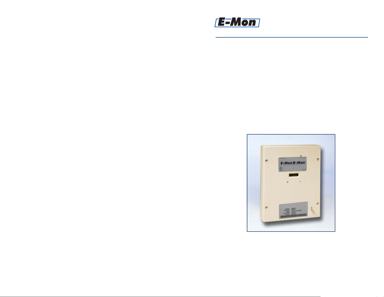
Class 4000 Single-Phase, Single-Point KWh Meter
Class 4100 Single Phase KWh Meter
with Built-In Wireless Communications
E-Mon, LLC
850 Town Center Drive
Langhorne, PA 19047
(800) 334-3666
www.emon.com - info@emon.com
11/08
E-Mon, LLC, 850 Town Center Drive, Langhorne, PA 19047
Page 2

Energy Monitoring Products
®
www.emon.com
info@emon.com
9.0 Meter Limited Warranty
Subject to the exclusions listed below, E-Mon will either repair or replace (at its
option) any product that it manufactures and which contains a defect in material
or workmanship.
The following exclusions apply:
Dear Valued Customer,
We are pleased that you chose to buy one of our products, and want you
to be just as pleased with owning it. Before installing your new E-Mon
product, please read the information on the following pages carefully.
We believe that you will fi nd the E-Mon D-Mon meters easy to install and
to use for monitoring and evaluating your electrical usage.
To be sure that you are 100% satisfi ed with your products, we provide
toll-free technical and sales support Monday through Friday, 8:00 am
to 7:30 pm, EST: (800) 334-3666. You may also reach us via email at
info@emon.com.
If you have questions, we can handle them quickly and effectively with
a telephone call. Please let us try to help you BEFORE you remove
your meter. And to help us help you, we ask that you have all relevant
information on hand when you call (model or part numbers, nature of
diffi culty, etc.)
Be sure to forward this manual to the owner after installation is complete,
so that they may use it as a reference guide when reading the E-Mon
D-Mon meter.
Thank you.
®
Energy Monitoring Products
1. This Limited Warranty is only effective for a period of (5) fi ve years following the date
of manufacture when installed in accordance with manufacturer’s instructions by qualifi ed
personnel.
2. E-Mon must be notifi ed of the defect within ninety (90) days after the defect becomes
apparent or known.
3. Buyer’s remedies shall be limited to repair or replacement of the product or component which failed to conform to E-mon’s express warranty set forth above.
4. Buyer shall be responsible for all freight costs and shall bear all risk of loss or damage
to returned goods while in transit.
5. This Limited Warranty does not cover installation, removal, reinstallation, or labor
costs, and excludes normal wear and tear. Buyer shall provide labor for the removal of the
defective component or item and installation of its replacement at no charge to E-Mon.
6. This Limited Warranty does not cover any product if: (i) a product is altered or modifi ed from its original manufactured condition, (ii) any repairs, alterations or other work has
been performed by Buyer or others on such item, other than work performed with E-Mon’s
authorization and according to its approved procedures; (iii) the alleged defect is a result
of abuse, misuse, improper maintenance, improper installation, accident or the negligence
of any party; (iv) damaged as a result of events beyond E-Mon’s control or other force
majeure events or (v) used in conjunction with equipment, components, accessories, parts
or materials not supplied or approved by E-Mon.
7. This Limited Warranty is limited to the obligation to repair or replace the manufactured
product. This is the sole and exclusive remedy for any breach of warranty. IN NO EVENT
SHALL E-MON BE LIABLE FOR ANY INDIRECT, INCIDENTAL, SPECIAL, CONSEQUENTIAL OR PUNITIVE DAMAGES (INCLUDING ANY DAMAGE FOR LOST PROFITS)
ARISING OUT OF OR IN CONNECTION WITH THE FURNISHING OF PRODUCTS,
PARTS OR SERVICES, OR THE PERFORMANCE, USE OF, OR INABILITY TO USE ANY
PRODUCTS, PARTS OR SERVICES, SALE OF OR OTHERWISE, WHETHER BASED IN
CONTRACT, WARRANTY, TORT, INCLUDING WITHOUT LIMITATION, NEGLIGENCE,
OR ANY OTHER LEGAL OR EQUITABLE THEORY.
8. EXCEPT AS EXPRESSLY PROVIDED HEREIN, E-MON MAKES NO WARRANTY OF
ANY KIND, EXPRESS OR IMPLIED WITH RESPECT TO ANY PRODUCTS, PARTS OR
SERVICES PROVIDED BY E-MON INCLUDING, BUT NOT LIMITED TO, THE IMPLIED
WARRANTIES OF MERCHANTABILITY AND FITNESS FOR A PARTICULAR PURPOSE.
PRODUCTS OR COMPONENTS DISTRIBUTED, BUT NOT MANUFACTURED, BY
E-MON ARE NOT WARRANTED BY E-MON AND BUYER MUST INSTEAD RELY ON
THE REPRESENTATIONS AND WARRANTIES, IF ANY, PROVIDED DIRECTLY TO THE
BUYER BY THE MANUFACTURER OF SUCH PRODUCT OR COMPONENT.
Page 12
Page 3

8.0 Important Information For The Owner
To better assist the building owner/manager, the installer should complete the following
information and forward the installation manual to the building owner/manager for future
reference.
Table Of Contents
Section 1.0 Introduction Page 1
Product Information
Item Installed: ______________________________________________
Model Number: ______________________________________________
Serial Number: ______________________________________________
Date of Installation: ______________________________________________
Installer Information
Installed By: Company: ______________________________________
Name: _________________________________________
Phone: _________________________________________
Application Information
Purpose Of Installation: _______________________________________________
_______________________________________________
_______________________________________________
Notes/Comments: _______________________________________________
_______________________________________________
_______________________________________________
Section 1.1 Internal Electronic Assemblies Page 2-3
Section 2.0 Meter Technical Specifi cations Page 4
Section 3.0 Safety Label Defi nitions Page 5
Section 4.0 Precautionary and Safety Information Page 5
Section 5.0 Meter Installation Page 6
Section 5.1 Mounting the Meter Page 6
Section 5.2 Main Power Board Connections Page 6-7
Section 5.3 Current Sensor Installation and Wiring Page 7-9
Section 5.4 Main Power Page 9
Section 6.0 Features & Operating Guide Page 9
Section 6.1 Class 4100 Wireless Option Page 9
Section 7.0 Troubleshooting Guide Page 10
Section 8.0 Information For The Owner/Manager Page 11
Section 9.0 Meter Limited Warranty Page 12
_______________________________________________
Page 11
Page 4

1.0 Introduction
7.0 Troubleshooting Guide
The E-Mon D-Mon Class 4000/4100 meter is a 1 or 2-element meter with
optional RF wireless communications (Class 4100). The device is used to monitor electric power usage of individual loads after the utility meter and display kWh
consumption on a direct reading digital display. With the Class 4100 wireless RF
option, it will provide kWh and kW data for automatic meter reading. Installation
must only be performed by qualifi ed personnel and in accordance with these
instructions and all applicable local and national electrical codes. E-Mon
and its representatives assume no responsibility for damages or injury resulting
from the improper installation of this meter.
Verify the input voltage rating and confi guration on the unit panel label to ensure
that it is suitable for the intended electrical service. Class 4000/4100 meters
labeled for 120/208V service MUST NOT be installed on service feeds of
277/480 volts.
Verify that the Class 4000/4100 meter’s current sensors are sized suitably for the
load to be monitored. Compare the color of the arrows on the current sensors to
the chart below to confi rm the correct sensor is being used.
Sensor Arrow Color code Sensor Rating (Amps)
Brown 100 A
Red 200 A
Table 1.0.1. Sensor arrow color codes.
CAUTION: Internal circuit components are extremely sensitive to
electrostatic discharge. Prior to handling or touching
internal circuitry, discharge any static buildup on your
person. To discharge yourself, touch a grounded metal
object such as conduit or an earth-grounded metal
enclosure.
WARNING: Use of this instrument, the E-Mon D-Mon Class 4000/4100
meter, in a manner inconsistent with this manual or not
specifi ed by the manufacturer in writing, can cause
permanent damage to the unit and/or serious injury to the
operator. The protection and safety features provided by
this equipment may become impaired or otherwise
compromised.
The Class 4000/4100 electronic kilowatt-hour meter is calibrated and tested
at the factory before being packaged and shipped. If installed properly and in
accordance with these installation instructions, the Class 4000/4100 meter will
provide years of trouble-free service. If the meter should not function, the following guide will assist in troubleshooting the installation. If, after following the
procedures below, the meter still does not function, please call E-Mon’s technical
department at (800) 334-3666 BEFORE removing the meter.
Problem Procedure to follow
1. Display reads all ZEROs, A. Determine if the load is suffi cient
or is not incrementing. to update the display (A load of
less than 1% of the meter rating
may require 24 hours to change
the display reading.
B. Check the current sensor
installation.
C. Be sure that the current &
voltage inputs have proper
phase relationship.
D. Check wiring to voltage
terminals.
E. Check circuit breaker or fuses.
F. Test source for correct voltage.
2. Display reads only a fraction A. Check the supply voltage to be
of the power consumed. sure that it is on 24 hours a day.
B. Check the current sensors for
installation and polarity.
C. Check the current sensor to
verify that it is the correct amp
rating.
D. Check the sensor wiring to the
terminal block in the meter
(verify color coding white-to white and black-to-black.)
Note: If any troubles arise during the installation or functional
verifi cation operations, do not immediately remove the unit.
Before removing the unit, contact E-Mon’s technical support
and/or engineering department at (800) 334-3666. E-Mon’s
technical department will assist you in detailed troubleshooting
of the Class 4000/4100 meter installation and assist you in
getting the unit operating correctly.
Page 1
Page 10
Page 5

5.3.2 Current Sensor Wiring (continued)
1.1 Internal Electronic Assemblies
NOTE: When the E-Mon D-Mon® Class 4000/4100 meter is installed where the
tenant has access to the electrical panel powering the meter, it is suggested that
a dedicated breaker NOT be used to power the meter, as a dedicated breaker
can be shut off and stop the meter from recording. If a dedicated breaker must
be used, it should be a lockable style.
5.4 Main Power
After the meter circuit wiring has been examined for correctness, power may be
applied to the circuit board. If the monitored circuit is under load, the LED in the
meter’s upper right hand corner will actively blink - indicating the amount of load
by the frequency of its pulse. A heavy load will blink faster than a light load. Very
light loads will result in an extended blink time.
6.0 Features & Operating Guide
The 6-digit display shows the
kilowatt-hours consumed by
Load Indicating
LED
the metered load.
The blinking LED indicator
provides a visual pulse signal
of the meter’s load. A heavier
6-Digit Display
kWh Reading
load will increase the blink
frequency.
Sealing T ab
* The sealing tab provides the
(Optional)
meter with a location to install
a utility type security seal.
NOTE: Depending on the amount of power being used, a period of time will
elapse before the meter registers. In the case of light loading, this could be as
much as several hours.
6.1 RF Wireless Metering Option (Class 4100)
The unit is comprised of one or two subassembly boards, the meter board and
the optional RF board (Class 4100). Both circuit cards are mounted inside the
non-metallic enclosure.
Note: Units are suitable for indoor applications only.
RF Board
(Class 4100)
Meter
Board
Figure 1.1 Internal electronic assemblies.
1.1.1 Meter Board
Connections to this board include the MAINS input voltage and current
sensors. The MAINS input terminals (TB1) are covered with a protective clear
shield for safety purposes. The current sensor assemblies interface to two
header connections, TB2, and TB3. Each header connector input corresponds
to an input voltage phase; care must be exercised to ensure that each current
sensor is connected to the correct input header.
Figure 1.1.1 Meter board connections.
When the meter is ordered with the RF option (Class 4100), it will be provided
with a factory installed 900 mHz RF module for AMR (Automatic Meter
Reading.) This module is pre-wired to the meter and will be active when the
meter is powered.
This module is designed to be used with E-Mon Energy™ software and an
available RF Wireless Gateway for either on-site reading or through an internet
connection. The system requires factory start-up services. Contact E-Mon for
additional details.
Page 9
TB1
TB2 & TB3
Page 2
Page 6

1.1.1 Meter Board (continued)
5.3.1 Installing the Split-Core Current Sensor Assembly (continued)
The Class 4000/4100 meter displays electrical consumption (kWh) on its 6-digit,
electro-mechanical display, and is read directly - without multipliers. An LED on
the board pulses in response to the load, with the speed of the pulse indicating
the amount of load (a heavier load will blink more rapidly).
1.1.2 RF Board (Class 4100)
The optional RF board (Class 4100) connects to the meter board via two pair of
conductors. One pair supplies power (5 VDC) to the RF board and the other pair
supplies a pulse signal that is stored as interval data. The accumulated data is
normally transmitted on a daily basis through its on-board antenna. This data is
transmitted pier-to-pier, then utilized for AMR (Automatic Meter Reading). The
RF board operates in the 900 MHz range with a maximum transmitting power of
100 mw.
5 VDC In
Figure 1.1.2 RF Board (Class 4100)
Pulse In
Antenna
2. Reassemble the current sensor assembly around the conductor(s) to be
monitored. Ensure the current sensor halves marked “Load” are both
facing the load side of the conductor. The colored arrow will be on the
source side of the conductor being monitored and MUST be pointed in a
clockwise direction around the conductor being monitored. Tighten the
nylon clamp to complete the assembly.
IMPORTANT: When looking from the source side of the conductor(s)
being monitored, you should see the arrow on the current
sensor assembly. The arrow should be pointing in a
clockwise direction around the conductor(s) being
monitored. If the arrow is not positioned on the source
side, inaccurate readings will result.
5.3.2 Current Sensor Wiring
Once the current sensors are installed onto their appropriate phase conductors,
you can begin terminating the current sensors onto the Class 4000/4100 meter
board using the two-screw removable terminal plug. The current sensor leads
can be extended up to 2,000 feet from the meter. To extend the length of the
wires, use #22 AWG twisted-pair wire with one white and one black wire.
Page 3
The current sensor connected to TB2 must be on the same phase as the MAINS
voltage terminal A and the current sensor connected to TB3 must be on the same
phase as the MAINS voltage terminal B. Failure to do so may result in inaccurate
readings.
1-Phase, 2-Wire Connection
120-Volt or 277-Volt Single-Phase
Line Voltage Current Sensors
C
AB
LOAD SOURCE
A
W B N
B
W B
A
N
Single-Phase, 3-Wire Connection
120/240-Volt Single-Phase
Line Voltage
AB
**
LOAD SOURCE
C
Current Sensors
A
W B W B N
B
A
B
N
Page 8
Page 7

5.2 Meter Board Connections (continued)
2.0 Meter Technical Specifi cations
3. External Switch Mechanism/In-Line Fuse Installation
To ensure a safe installation, the Class 4000/4100 requires an external
switch mechanism, such as a circuit breaker (max. 15 amps), be
installed to the Class 4000/4100 MAINS input wiring. The switch
mechanism must be installed in close proximity to the Class 4000/4100
and easily reachable for the operator. This device must also be marked
as the disconnecting device for the Class 4000/4100. Install 1/10 amp
Slow Activation inline fuses with the suitable voltage rating for
each conductor Phase at the MAINS input to the meter. The fuses must
be labeled to indicate voltage and current rating as well as element
characteristics. The fuse element must be slow activating type.
5.3 Current Sensor Installation & Wiring
The meter board contains two plug-in connectors located at the bottom center
of the board, TB2 and TB3. (See Figure 1.1.1) Connector TB2 is the input for
Phase A, and TB3 is the input for Phase B.
The Class 4000/4100 meter can be used with two types of current sensors:
1. Split-core current sensor. This sensor opens so that it can be attached
around the circuit being monitored without interrupting power. Unless
otherwise specifi ed, all Class 4000/4100 meters are supplied with this
sensor type.
2. Solid-core current sensor. This sensor does not open and requires the
monitored conductor to be removed from the circuit to install the current
sensor. This type is only supplied when specifi ed at time of order.
5.3.1 Installing the Split-Core Current Sensor Assembly
1. Each phase being monitored will require one two-piece current sensor
assembly. Open the two-piece current sensor assembly by releasing
the nylon clamp using a fl athead screwdriver.
Ordering Information: Defi ne input voltage, current sensor rating and the RF
option, in the format C-xxx-yyyy-zz, where
xxx=input voltage (120 or 208 [120/208/240])
yyy=current sensor rating (100, 200)
zz=designated option (W=none [Class 4000], WT (RF transceiver [Class 4100])
Example: 3 208 200 W
Number of conductors (3)
Input Voltage (208)
Current Sensor (200A)
RF Transceiver (none)
C = number of conductors (2 or 3)
Input Voltage Confi guration 2-wire 120-volt, 3-wire 120/240-volt, 3-wire 120/208 volt
MAINS Voltage Input Up to 240 VAC
Input Power 6 VA maximum rating
Current Sensor Rating Up to 200 amps RMS AC available
Power Factor 0.5 leading or lagging
Line Frequency 50-60 Hz
Metering Accuracy Certifi ed to ANSI C12.16 (+/-1% from 1-100% of rated load)
Voltage Operating Range +/-10% of rated load
Temperature Range -20 degrees C to +50 degrees C
Relative Humidity Range 0-95% non-condensing
Altitude 2000 meters maximum
Voltage Overload +25% continuously; +100% for 20 cycles
Current Sensor Overload 100% for 1 minute without damaging meter
Pollution Degree Degree 2 in accordance with IEC 664
Installation (Overvoltage) Category Category III
Measurement Category Category III
Enclosure Material ABS 94VO
Display Readout 6-digit electro-mechanical
Standard Ranges (2-wire) 120 VAC, 100, 200 Amp
(3-wire) 120/208/240 VAC, 100, 200 Amp
Modem Interface None
RS-485 Serial Communications None
Load Control None
Recommended In-Line Fuse Manufacturer: Littlefuse
Mfg Part No.: 313.100
Rating: 100mA, Slo-Blo, 250 VAC cartridge fuse
Page 7
Table 2.0.1 Class 4000/4100 meter technical specifi cations.
Page 4
Page 8

3.0 Safety Label Defi nitions and Information
5.0 Meter Installation
The Class 4000/4100 meter may contain one or more of the following labels.
Operator(s) should familiarize themselves with the meaning of each label to
minimize risk.
The presence of this label is a cautionary indicator
identifying a danger risk. The manual should be
consulted prior to proceeding.
The presence of this label indicates an electrical
shock hazard exists in the location or area where
the label is placed. Prior to proceeding, the MAINS
power must be disconnected and the manual
consulted for safety information.
4.0 Precautionary/Safety Information
5.1 Mounting the Class 4000/4100 Meter
Use appropriately sized mounting hardware to fasten the Class 4000/4100
enclosure to the selected mounting surface. The four mounting holes are located
inside the enclosure and are accessed by removing the cover. The mounting
holes are centered 6 13/16” H x 4 13/16” W.
NOTE: Units must only be installed in indoor environments, where they will not
be affected by the elements.
5.2 Meter Board Connections
1. Wire Entry:
Two 1/2” conduit openings are located on the back of the unit enclosure.
These openings are used for bringing in MAINS power and for current
sensor wiring. Route the appropriate cabling to and through the
respective enclosure opening.
After installing the conduit fi tting and conduit, verify that each conduit
slip nut is securely tightened to its respective conduit fi tting.
2. Unit MAINS wiring:
The 4-position terminal block TB1, located at the bottom left corner of
the meter board, is clearly labeled A, B, C, N (neutral). AWG 14 or 12
gauge (stranded) conductors are typically utilized for this connection.
WARNING: High voltages present on main PCB terminal block TB1.
Risk of serious injury and/or electrical shock exists. Prior
to performing any wiring operations, review all contents of
the user manual and de-energize the MAINS power switch.
Only qualifi ed personnel should perform installation
wiring. Installation wiring must comply with all local and
national electrical codes.
WARNING: NEVER open front panel of unit while unit has MAINS
power applied. Failure to comply can increase the risk of
serious injury and/or electrical shock.
Page 5
Figure 5.2.1.
Terminal block TB1.
A. Connect the NEUTRAL wire to the appropriate terminal block position.
B. On 2-wire, 120 VAC installations, connect the AC main power wire to the
Phase A position as labeled on terminal block TB1. On 3-wire 120/208
VAC installations connect the AC main power wires to Phase A and
Phase B positions on terminal block TB1. After all conductors are
connected to their respective terminal block positions and tightened
down, verify that each terminal block screw is securely fastened by
gently tugging on each conductor. Verify that no conductor wires
are frayed or shorting to adjacent terminal block positions.
Page 6
 Loading...