

Page 1
Preliminary
DATASHEET Ɩ EMBP00
Copyright 2019, EM Microelectronic-Marin SA
EMBP00-DS, Version 0.1, 3-Apr-19
1
www.emmicroelectronic.com
EM MICROELECTRONIC - MARIN SA
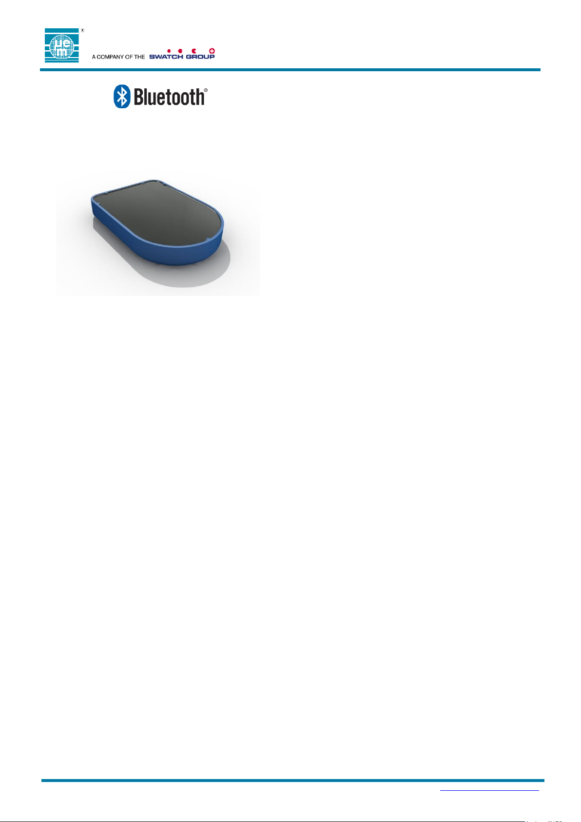
Low-Energy Proximity Beacon
With Accelerometer
FEATURES
Ɩ Small, rugged and encapsulated in polymer resin
Ɩ Low-cost and easy to use
Ɩ Supports popular beacon formats such as iBeacon™,
Eddystone™, AltBeacon™, and proprietary such as
Quuppa Intelligent Locating System™
Ɩ Unique and scannable QR-code come standard
Ɩ Accelerometer can be used to activate beaconing on
actions such as movement or gestures
Ɩ Secure over-the-air updates possible with all major
mobile platforms in the field
Ɩ Multiple interleaved packet types with customizable
parameters:
Ɩ Packet types, including custom packet types
Ɩ Device name, address, manufacturer name, model
number, HW/SW revision
Ɩ UUID, Major/Minor ID, UID or URL
Ɩ Beacon interval, Transmitter power
Ɩ Accelerometer function and sensitivity
Ɩ A key benefit of EMBP00 is the extremely rich set of
parameters configurable Over the Air which allows it
address a very large range of applications without
modifying firmware.
Ɩ Up to 10 years of battery life, depending on
advertisement configuration
Ɩ Battery lifetime calculator available
Ɩ Up to 50m range line-of-sight (LOS) at maximum output
power
Ɩ Weatherproof Enclosure
Ɩ Temperature range from -20C to +60C
Ɩ Modular Bluetooth V5.0, FCC, IC, and CE certified,
RoHS and REACH compliant
Ɩ Made with Swatch Electronics Group technologies:
Ɩ EM Microelectronic EM9304 Bluetooth V5.0 SOC
Ɩ Renata CR2032 coin-cell battery
DESCRIPTION
The EMBP00 is a high-performance, customizable
Bluetooth V5.0 low energy proximity beacon with an
accelerometer for advanced functionality. The small and
rugged EMBP00 comes fully encapsulated with a resin
based polymer for protection against dust and liquids and
reliable use in harsh environmental conditions. The beacon
has been optimized for low-cost and ease of use.
The EMBP00 is compatible with major beacon formats
including iBeacon™, Eddystone™, AltBeacon™, and
trackable with proprietary systems such as the Quuppa
Intelligent Locating System™. The beacon is fully
customizable over the air or in manufacturing. For example,
the following parameters can be easily modified:
Packet types, including custom packet type
Device name, address, manufacturer name, model
number, HW/SW revision
UUID, Major/Minor ID, UID or URL
Beacon interval
Transmitter output power
Accelerometer function and sensitivity
The EMBP00 accelerometer can be used to implement
efficient and low-energy algorithms for various applications.
The accelerometer can be used to activate beaconing on
movement, or gestures, for example. When not active, the
beacon consumes minimal energy.
The EMBP00 can be stored in Warehouse Mode without
significantly degradation the battery lifetime and up to 10
years of battery life depending on usage conditions.
The EMBP00 can be delivered in any quantity with
guaranteed unique ID. A 2D unique serial number is printed
on the beacon for optical scanning.
The EMBP00 comes is weather resistant and operates over
a -20C to +60C temperature range. The EMBP00 is
Bluetooth V5.0, FCC, IC, and CE certified, RoHS and
REACH compliant.
Page 2
Preliminary
DATASHEET Ɩ EMBP00
Copyright 2019, EM Microelectronic-Marin SA
EMBP00-DS, Version 0.1, 3-Apr-19
2
www.emmicroelectronic.com
TABLE OF CONTENTS
1. GENERAL DESCRIPTION ................................................................................................................................ 3
2. ENVIRONMENTAL AND STORAGE CONDITIONS ......................................................................................... 4
3. PRODUCT OUTLINE DIMENSIONS ................................................................................................................. 4
FINISHED PRODUCT .................................................................................................................................... 4
4. MODELS IN PRODUCT FAMILY ...................................................................................................................... 4
5. MECHANICAL ................................................................................................................................................... 5
MATERIALS................................................................................................................................................. 5
ACCELEROMETER ....................................................................................................................................... 5
6. ELECTRICAL ..................................................................................................................................................... 5
HANDLING PROCEDURES AND ABSOLUTE MAXIMUM RATINGS ....................................................................... 5
GENERAL OPERATING CONDITIONS ............................................................................................................. 6
ELECTRICAL CHARACTERISTICS .................................................................................................................. 6
REGULATORY ............................................................................................................................................. 6
6.4.1. Regulatory Information CE ....................................................................................................... 6
6.4.2. Regulatory Information USA ..................................................................................................... 7
6.4.3. Regulatory Information Canada ................................................................................................ 7
7. FIRMWARE ........................................................................................................................................................ 8
STATE MACHINE OPERATION....................................................................................................................... 8
7.1.1. State Machine Configuration Options ....................................................................................... 9
7.1.2. Hardware Features ................................................................................................................... 9
7.1.3. Operating Modes ...................................................................................................................... 9
7.1.4. Mode Transitions .................................................................................................................... 13
7.1.5. Accelerometer Configuration .................................................................................................. 14
ADVERTISEMENTS..................................................................................................................................... 15
7.2.1. Device Address ....................................................................................................................... 15
7.2.2. Advertising Channels .............................................................................................................. 15
7.2.3. RSSI Table .............................................................................................................................. 16
7.2.4. Connectable Advertisement .................................................................................................... 16
7.2.5. Non Connectable Advertisements .......................................................................................... 16
SUPPORTED BLE SERVICES ..................................................................................................................... 17
7.3.1. Firmware Over The Air (FOTA) Service ................................................................................. 17
7.3.2. Beacon Information Service .................................................................................................... 17
7.3.3. Device Information Service ..................................................................................................... 18
8. TYPICAL FIELD ACTIVATION ........................................................................................................................ 19
9. UNIT LABEL .................................................................................................................................................... 19
SERIAL NUMBER ....................................................................................................................................... 20
10. PACKING AND LABELING ............................................................................................................................. 20
FINISHED PRODUCT .................................................................................................................................. 20
10.1.1. Inner Packing .......................................................................................................................... 20
10.1.2. External Packing ..................................................................................................................... 20
11. ENVIRONMENTAL SAFETY ........................................................................................................................... 21
RESTRICTION OF HAZARDOUS SUBSTANCES (ROHS) ................................................................................. 21
"HALOGEN FREE" - IEC 61249-2-21:2003. ............................................................................................... 21
REACH AND SVHC LIST .......................................................................................................................... 21
PRODUCT HARDWARE RECYCLING (WEEE) .............................................................................................. 21
12. ORDERING INFORMATION ............................................................................................................................ 23
13. CONTACT INFORMATION .............................................................................................................................. 23
14. REFERENCE DOCUMENTS ........................................................................................................................... 23
Page 3

Preliminary
DATASHEET Ɩ EMBP00
Copyright 2019, EM Microelectronic-Marin SA
EMBP00-DS, Version 0.1, 3-Apr-19
3
www.emmicroelectronic.com
1. GENERAL DESCRIPTION
The EMBP00 is a 2.4 GHz RF electronic beacon with proximity capability, compatible with most common beacon standards
with a low cost design for mass production, and includes a low-power accelerometer for activation features.
Over-the-air configurable:
Up to 10 advertisements running parallel and uniquely defined
o Multiple Industry Standard Packet Types
iBeacon™
altBeacon™
Eddystone™ UID, URL and TLM
User Defined fixed payload
o Wide range advertisement interval
From 30ms to 18hrs
o 17 Output Power Steps
From +6dBm to -34dBm
o Activity Gated Advertising Options
Continuous Advertising
Advertising On Activity
Advertising When Not Active
Simple state machine
o Optional factory enabled event to enter Configuration Mode using a flip motion
o Optional user enabled event to transition between Warehouse and Beaconing Mode using a flip motion
o User configurable timeouts from the Configuration and Active Modes
From 100ms to 1.8hrs
o User defined events to activate Activity Mode
Motion, tap, double tap, freefall or flip
Flexible accelerometer settings
o Control of sensitivity, sampling rates, duration, etc. settings
Long Range:
30m LOS at 0dBm
50m LOS at max output power
Long Battery Life:
225mAh CR2032 Li 3V battery
Up to 10 years storage life
Normal Operating Conditions:
-20 to +60 C
Weather proof
Small and Lightweight:
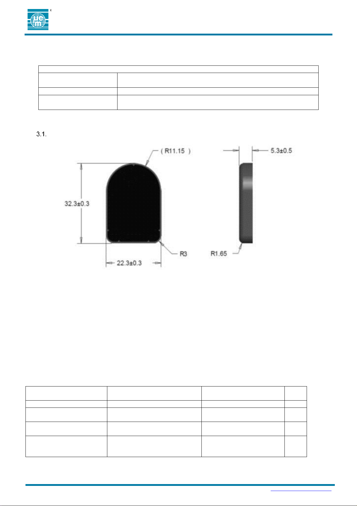
32.3 x 22.3 x 5.3 mm outer dimensions
7 grams
Certifications:
Environmental: RoHS, REACH, Halogen Free
RF: FCC, IC, CE
Compatible With:
Bluetooth Smart Ready Devices
Most Common Beacon Standards
EMBC Configuration Tool
A free smart phone and tablet application for
Android to update the operating parameters
Included Hardware:
A blue plastic enclosure filled with black
polymer resin
A permanent label with a unique serial
number and QR Code
Battery Size:
Standard in EMBP00 housing is
CR2032/225mAh battery
Fully Customizable:
Rich set of modifiable parameters over-the-
air.
Page 4
Preliminary
DATASHEET Ɩ EMBP00
Copyright 2019, EM Microelectronic-Marin SA
EMBP00-DS, Version 0.1, 3-Apr-19
4
www.emmicroelectronic.com
Table 1: Environmental and storage conditions
Module operating temperature
and humidity range
-20°C to 60°C and 0 to 85% RH
Weatherproof
Module can be used in outdoor conditions.
Module storage temperature
and humidity range
Modules must be stored in original EM packing at Temp=25°C±5°C / RH 30-45%.
PRODUCT MODEL NAME
PCB Variant
BOM Variant
Cup
Color
EMBP00
RevA
Full BOM
Teal
EMBP01
RevD
Solder mask change from RevC
DNP 1 sensor + 2 passives
Blue
EMBP02
RevC
Solder mask change from RevB
DNP 1 sensor + 2 passives
+ LFXTAL
Red
EMBP03
RevB
Minor copper change from RevA
in digital section only
Full BOM
Teal
2. ENVIRONMENTAL AND STORAGE CONDITIONS
The operating and storage conditions are listed in Table 1.
3. PRODUCT OUTLINE DIMENSIONS
FINISHED PRODUCT
The finished product outline dimensions are shown in Figure 1.
Figure 1: EMBP00 finished product outline dimensions
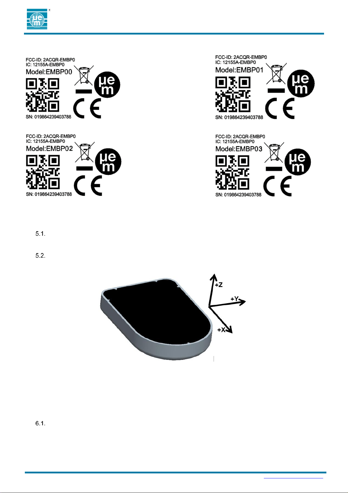
4. MODELS IN PRODUCT FAMILY
FCC-ID: 2ACQR-EMBP0
IC: 12155A-EMBP0
The FCC and IC identifications above apply to a base product with the model number EMBP01. In this product
family we also have EMBP00, EMBP02, and EMBP03. This documents shows the differences between the
products and shows the label relevant to each product in the family.
PRODUCT MODELS IN THE FAMILY
Page 5
Preliminary
DATASHEET Ɩ EMBP00
Copyright 2019, EM Microelectronic-Marin SA
EMBP00-DS, Version 0.1, 3-Apr-19
5
www.emmicroelectronic.com
LABELS FOR EACH MODEL IN THE FAMILY (EMBP00 , EMBP01 , EMBP02 , EMBP03)
5. MECHANICAL
MATERIALS
PA66 Zytel 101E NC010 Blue casing filled with WEVOPUR 552FL with WEVONAT 300.
ACCELEROMETER
The accelerometer is an LIS2DWL MEMS digital output motion sensor for measuring high-performance ultra-lowpower 3-axis "femto" acceleration. The X-Y-Z orientation of the accelerometer are as shown in Figure 2.
Figure 2: EMBP00 XYZ orientation of the accelerometer in final product
6. ELECTRICAL
Typical values are stated at room temperature (T=25oC) with a supply voltage of VCC=3.0V.
HANDLING PROCEDURES AND ABSOLUTE MAXIMUM RATINGS
The finished product is compliant with EN 61000-4-2 (Electrostatic Discharge) level 2: 4kV contact discharge and 8kV
air discharge.
Stresses above these listed maximum ratings may cause permanent damage to the device. Exposure beyond
specified operating conditions may affect device reliability or cause malfunction
Page 6

Preliminary
DATASHEET Ɩ EMBP00
Copyright 2019, EM Microelectronic-Marin SA
EMBP00-DS, Version 0.1, 3-Apr-19
6
www.emmicroelectronic.com
Table 2: General Operating Conditions
Parameter
Min
Typ
Max
Unit
Supply Voltage (VCC)
2.0
3.0
3.6
V
Temperature Range
-20
25
+60
°C
Humidity Range
0
25
85
RH
Table 3: Battery Life-Time and Range Use Case Example
Operating Mode
Specification
Typical
Value
Unit
Use Case
Operating
Parameters
Warehouse Mode
Storage Time
1
years
Average Current
3.8
µA
Beaconing Mode
Beacon Interval In Active Mode
1000
msec
Output Power In Active Mode
0
dBm
Average Current In Active Mode
15
µA
Average Current in Inactive Mode
2.5
µA
Line-of-Sight(LOS) Range
30
m
Use Case
Battery Life
Based on
Activity Level
Example 1:
10% Activity
Percentage of Life in Active Mode
10
%
Percentage of Life in Inactive Mode
90
%
Lifetime Average Current
5.0
µA
Battery Lifetime (CR2032)
52
months
Example 2:
50% Activity
Percentage of Life in Active Mode
50
%
Percentage of Life in Inactive Mode
50
%
Lifetime Average Current
10
µA
Battery Lifetime (CR2032)
26
months
Example 3:
90% Activity
Percentage of Life in Active Mode
90
%
Percentage of Life in Inactive Mode
10
%
Lifetime Average Current
15.1
µA
Battery Lifetime (CR2032)
17
months
GENERAL OPERATING CONDITIONS
The general operating conditions are listed in Table 2.
ELECTRICAL CHARACTERISTICS
The electrical characteristics are given in Table 3 for a typical use case. A battery lifetime calculator is available to
estimate battery the battery lifetime with alternate configurations.
Unless otherwise specified: VCC=3.0V, T=25°C.
Note 1: Battery Lifetime is calculated based on the average current using a Renata CR2032 battery with 225mAh of
battery life under typical conditions.
Note 2: Beacon interval is the Bluetooth advertising interval (advInterval) as defined in the Bluetooth Specification
V5.0, Volume 6, Part B, Section 4.4.2.2.
Note 3: Range is measured outdoors, line-of-sight, with an iPhoneTM. 4S
REGULATORY
EMBP00 is certified and complies with the following regulatory requirements:
6.4.1. Regulatory Information CE
EM Microelectronic, as the responsible party for regulatory compliance, declares under our sole responsibility
that as delivered the described product is in conformity with the RED Radio Equipment Directive 2014/53/EU,
following the provisions of ERP Directive 2009/125/EC, EU RoHS Directive 2011/65/EU, including the
amendment 2015/863/EU on the restriction of the use of certain hazardous substances in electrical and
electronic equipment, and carries the CE-marking. Refer to emmicroelectronic.com for the signed declaration.
Page 7

Preliminary
DATASHEET Ɩ EMBP00
Copyright 2019, EM Microelectronic-Marin SA
EMBP00-DS, Version 0.1, 3-Apr-19
7
www.emmicroelectronic.com
Table 4: FCC Permitted Antenna
Type
Max Gain
Integrated PCB IFA
1.5 dBi
Table 5: IC Permitted Antenna
Type
Max Gain
Integrated PCB IFA
1.5 dBi
Table 6: IC Permis Antenne
Type
Max Gain
Integrated PCB IFA
1.5 dBi
SAFETY File
1. Information on all plastics (flame rating and UL listing) model numbers
2. Battery: Specification, UL listing, and reports from vendor (Standards are UL 1642 and IEC/EN
62133)
3. PCB Board (same information as plastics)
6.4.2. Regulatory Information USA
Changes or modifications not expressly approved by the party responsible for compliance could void the
user’s authority to operate the equipment.
Part 15 – General emissions
Part 15.247:2011 – Operation within the band 2.4-2.4835GHz
This device complies with part 15 of the FCC Rules. Operation is subject to the following two conditions: (1)
This device may not cause harmful interference, and (2) this device must accept any interference received,
including interference that may cause undesired operation.
Permitted Antenna
This radio transmitter model, FCC ID: 2ACQR-EMBP0 has been approved by FCC to operate with the
antenna types listed below with the maximum permissible gain indicated. Antenna types not included in
this list, having a gain greater than the maximum gain indicated for that type, are strictly prohibited for use
with this device.
6.4.3. Regulatory Information Canada
Changes or modifications not expressly approved by the party responsible for compliance could void the
user’s authority to operate the equipment.
Les changements ou modifications non expressément approuvés par la partie responsable de la conformité
pourraient annuler l'autorisation de l'utilisateur d'utiliser l'équipement.
This device complies with Industry Canada’s license-exempt RSSs. Operation is subject to the following two
conditions: (1) This device may not cause interference; and (2) This device must accept any interference,
including interference that may cause undesired operation of the device.
Le présent appareil est conforme aux CNR d'Industrie Canada applicables aux appareils radio exempts de
licence. L'exploitation est autorisée aux deux conditions suivantes : (1) l'appareil ne doit pas produire de
brouillage, et (2) l'utilisateur de l'appareil doit accepter tout brouillage radioélectrique subi, même si le
brouillage est susceptible d'en compromettre le fonctionnement.
ICES-003 – General emissions
RSS-210:2010 – Low-power License exempt Radio Communication Devices
Permitted Antenna
This radio transmitter model, IC: 12155A-EMBP0 has been approved by the ISED to operate with the
antenna types listed below with the maximum permissible gain indicated. Antenna types not included in
this list, having a gain greater than the maximum gain indicated for that type, are strictly prohibited for use
with this device.
Le présent émetteur radio modèle, IC: 12155A-EMBP0 a été approuvé par ISDE pour fonctionner avec
les types d'antenne énumérés ci-dessous et ayant un gain admissible maximal. Les types d'antenne non
inclus dans cette liste, et dont le gain est supérieur au gain maximal indiqué, sont strictement interdits
pour l'exploitation de l'émetteur.
Page 8
Preliminary
DATASHEET Ɩ EMBP00
Copyright 2019, EM Microelectronic-Marin SA
EMBP00-DS, Version 0.1, 3-Apr-19
8
www.emmicroelectronic.com
Beaconing Mode
Adverts ON
(a) Event disabled after Lock Event occurs
(b) Event can be configured transition to “Beaconing”, rather than “Wa rehouse” Mode
(c) Disabled by POST failure
Battery Insert
Power On
Self Test
Warehou se Mode
Adverts OFF
Configuration Mode
Connectable Adverts
Config Timeout
(b,c)
POST Pass
(b)
Config Event
On/Off Event
(b,c)
On/Off Event
(b)
Lock Event
Config Event
(a)
Activity Mode
Adverts ON
when Triggered
Inactivity Mode
Adverts ON
when NOT Triggered
Lock Event
(c)
Activity Timeout
Activty Event
CAN ICES-3 (A/B)/NMB-3(A/B)
This Class A/B digital apparatus complies with Canadian ICES-003
Cet appareil numérique de clase A/B est conforme à la norme Canadienne ICES-003
7. FIRMWARE
The following is a basic description of EMBP00 firmware functionality with SimpleBeacon based firmware.
STATE MACHINE OPERATION
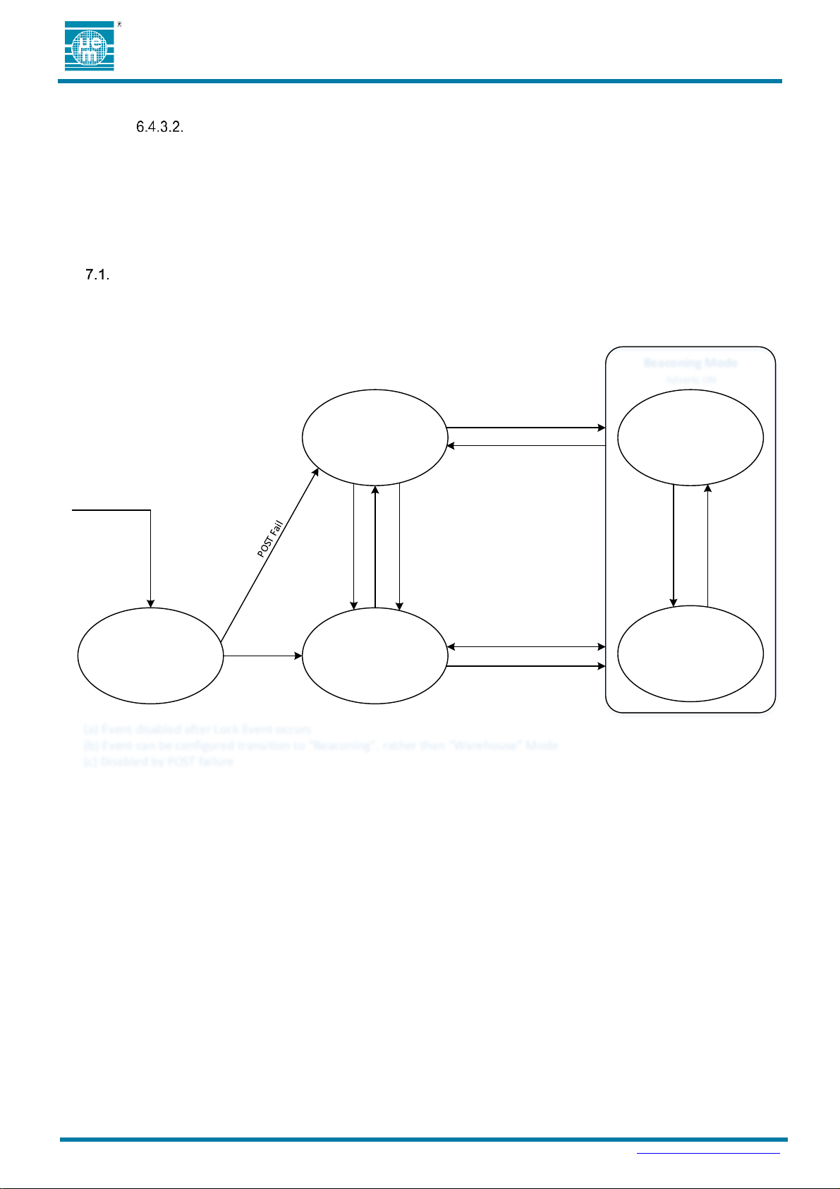
Figure 3 shows the base operating conditions of the SimpleBeacon firmware. Configuration options are available
and detailed in this section to enable, disable and modify a variety of the operating conditions of the core state
machine. Operating modes of the state machine are indicated by blocks in the diagram and transition events are
indicated with arrows.
Figure 3: Firmware State-Diagram
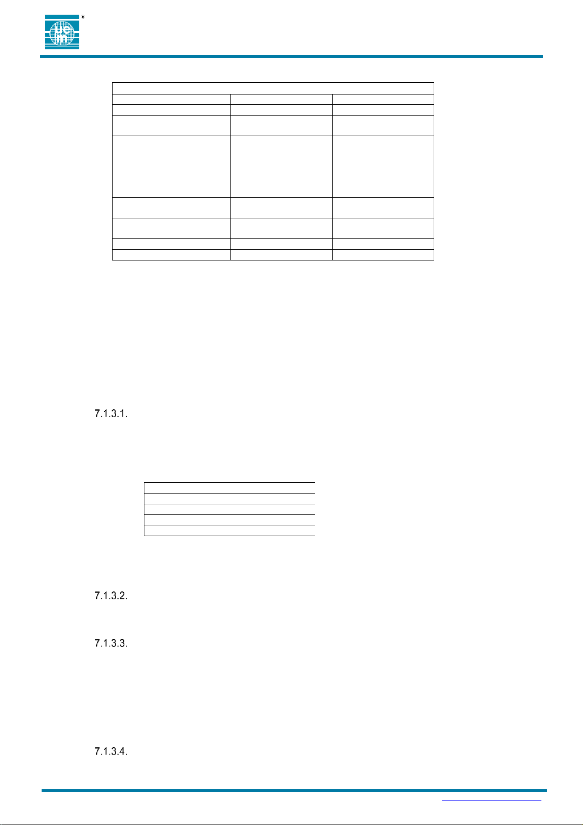
The tables in this section lists options available for update using the SimpleBeacon Configuration Tools. Contact EM for
technical details on creating custom configuration files outside of the SimpleBeacon Configuration Tools.
Page 9
Preliminary
DATASHEET Ɩ EMBP00
Copyright 2019, EM Microelectronic-Marin SA
EMBP00-DS, Version 0.1, 3-Apr-19
9
www.emmicroelectronic.com
Table 7: State Machine Configuration Options
Parameter
Options
Default Settings
Hardware Features
Accelerometer
All Enabled
Startup Mode
Warehouse Mode
Beaconing Mode
Beaconing Mode
Activity Event Source
Disabled
Movement
Tap
Double Tap
Freefall
Flip
Disabled
On/Off Event Source
Disabled
Flip
Disabled
Configuration Event
Source
Disabled
Flip
Flip
Configuration Timeout
0.1 to 6553.5 seconds
60 sec
Activity Timeout
0.1 to 6553.5 seconds
60 sec
Table 8: POST Tested Features
Accelerometer
48MHz High Frequency Crystal
32kHz Low Frequency Crystal
Invalid Configuration
7.1.1. State Machine Configuration Options
7.1.2. Hardware Features
The accelerometer may be disabled in firmware. The option to disable this hardware feature is unavailable in
the standard release of the SimpleBeacon Configuration Tools. Options to control these features can be made
available on request.
7.1.3. Operating Modes
Operating Modes of the EMBP00 are indicated with ovals in Figure 3. The modes are fixed unless code
patches are written and applied to redefine the states. Code patches may be developed using the EM
SimpleBeacon SDK. Behaviors within specific states, such as advertisement profiles in the Beaconing Mode,
can be redefined using the SimpleBeacon Configuration Tools. No source code development is required when
using the SimpleBeacon Configuration Tools.
Power-On-Self-Test (POST)
On reset, a self-test feature is run to confirm functionality of the key electrical components for advertising.
The self-test checks for hardware failures on the module. If the test passes, the device will enter the
specified Startup Mode. If the test fails, the device will enter the Configuration Mode until the Reboot
Delay timer has expired and resets the device. Table 8 shows the coverage of the tested hardware
features.
If a POST failure is detected the device will disable the accelerometer and enter Configuration Mode until
the Reboot Delay timer has expired and resets the device. From Configuration Mode the user can
reconnect and load a valid configuration and read the error code.
Startup Mode
The startup mode is the mode that will be entered after POST or on a Configuration Timeout Event. The
default definition of Startup Mode and reassignment options are as defined in Table 7.
Warehouse Mode
In Warehouse Mode, the EMBP00 is in its lowest consumption state to support long term storage. A
Configuration Event, On/Off Event or Lock Event will all initiate exiting the Warehouse Mode. If a
Configuration Event or On/Off Events are defined to use the flip option, the accelerometer will be
sampling at the rate defined in the accelerometer configuration settings. The consumption will increase
as defined in the accelerometer datasheet at the selected sampling rate. If the Configuration Event and
On/Off Event are not defined to use the flip option, the accelerometer is in a power down state and the
consumption of the device is as defined in Table 3. US the Battery Lifetime Calculator for more detailed
estimations for setting combinations.
Configuration Mode
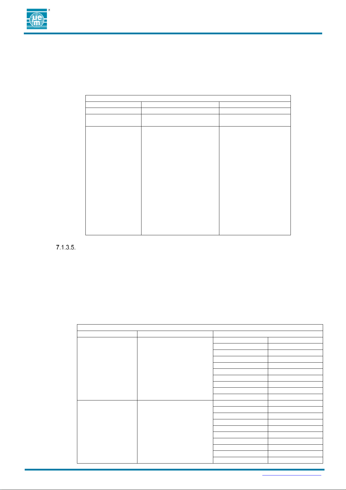
In Configuration Mode, the EMBP00 advertises a connectable advertisement at the default interval and
output power as defined in Table 9. The advertisement rate and output power may be redefined by the
Page 10
Preliminary
DATASHEET Ɩ EMBP00
Copyright 2019, EM Microelectronic-Marin SA
EMBP00-DS, Version 0.1, 3-Apr-19
10
www.emmicroelectronic.com
Table 9: Configuration Mode Advertisement Configuration Options
Description
Options
Default
Packet Type
Connectable
Connectable
Advertisement
Interval
30ms - 18hrs
500 ms
Tx Power Level
Settings (dBm)
6.2
4.6
2.5
0.4
-1.4
-2.6
-4
-5.5
-6.9
-8.4
-9.9
-11.4
-13.1
-14.6
-16.4
-17.9
-29
-33.5
0.4 dBm
Table 10: Beaconing Mode Advertisement Configuration Options
Description
Option
Default
Packet Type
iBeacon™
Eddystone UID™
Eddystone URL™
Eddystone TLM™
altBeacon™
Connectable
User Defined – Fixed Payload
Advertisement 1
Disabled
Advertisement 2
Disabled
Advertisement 3
Disabled
Advertisement 4
Disabled
Advertisement 5
Disabled
Advertisement 6
Disabled
Advertisement 7
Disabled
Advertisement 8
Disabled
Advertisement 9
Disabled
Advertisement 10
Disabled
Advertisement Interval
30ms - 18hrs
Advertisement 1
Disabled
Advertisement 2
Disabled
Advertisement 3
Disabled
Advertisement 4
Disabled
Advertisement 5
Disabled
Advertisement 6
Disabled
Advertisement 7
Disabled
Advertisement 8
Disabled
Advertisement 9
Disabled
Advertisement 10
Disabled
user. The configuration timer is started on entry into the Configuration Mode. If no connections are made
before the Configuration Timeout occurs, the EMBP00 returns to the Startup State. Exit from
Configuration Mode is initiated by Configuration Timeout. When a connection is made to the EMBP00,
the part will stay in a connected state until the master terminates the connection or is out of range. On
disconnect, the EMBP00 returns to the Startup State unless a reset was initiated during the connection.
The additional options to change the Packet Type is unavailable in the standard release of the
SimpleBeacon Configuration Tools. Options to control these features can be made available on request.
Beaconing Mode
In Beaconing Mode, the EMBP00 beaconing engine is enabled. The beaconing engine supports up to 10
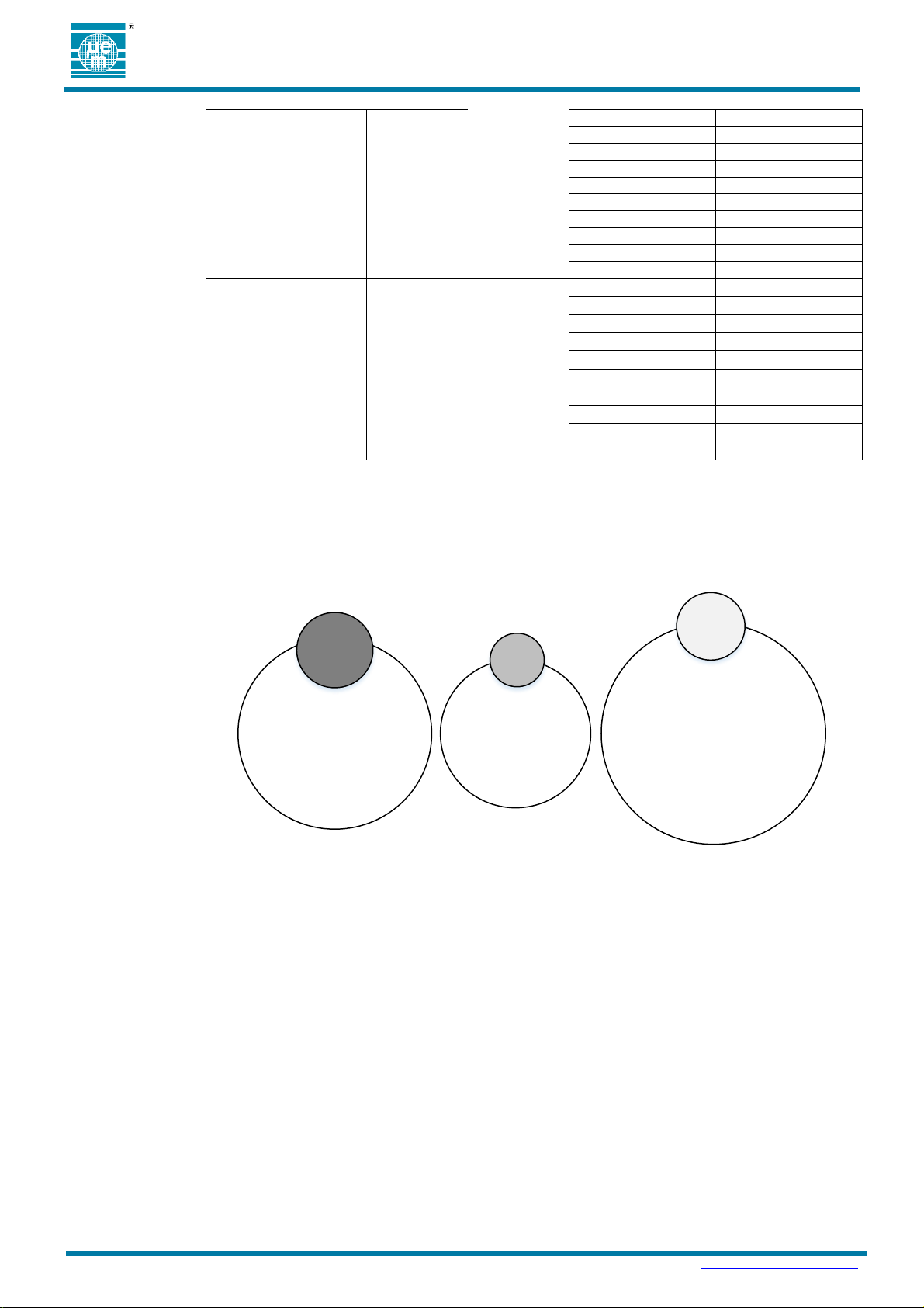
advertisements running in parallel. Each advertisement may have a unique Packet Type, Advertisement
Interval, and Transmit Power Level. In addition, each advertisement may be gated such that the
advertisement is Always Enabled, Enabled Only When Active or Enabled Only When Inactive from
Beaconing Mode. Table 10 shows the configuration options available for each advertisement.
Description of the transmit power level settings are from the EM9304 datasheet. Additional details
regarding the impact on the operating behavior, consumption and performance of the device can be
found in the datasheet. Modifications to the transmit output power and advertisement interval can have a
dramatic impact on battery life. Consult the EM9304 datasheet and battery lifetime calculator to calculate
the full impact of changes.
Page 11
Preliminary
DATASHEET Ɩ EMBP00
Copyright 2019, EM Microelectronic-Marin SA
EMBP00-DS, Version 0.1, 3-Apr-19
11
www.emmicroelectronic.com
Transmit Power Level
Settings (dBm)
+6.2
+4.6
+2.5
+0.4
-1.4
-2.6
-4.0
-5.5
-6.9
-8.4
-9.9
-11.4
-13.1
-14.6
-16.4
-17.9
-29.0
-33.5
Advertisement 1
+0.4
Advertisement 2
+0.4
Advertisement 3
+0.4
Advertisement 4
+0.4
Advertisement 5
+0.4
Advertisement 6
+0.4
Advertisement 7
+0.4
Advertisement 8
+0.4
Advertisement 9
+0.4
Advertisement 10
+0.4
Advertisement Gating
Off
Always Enabled
Enabled when Active
Enabled when Inactive
Advertisement 1
Disabled
Advertisement 2
Disabled
Advertisement 3
Disabled
Advertisement 4
Disabled
Advertisement 5
Disabled
Advertisement 6
Disabled
Advertisement 7
Disabled
Advertisement 8
Disabled
Advertisement 9
Disabled
Advertisement 10
Disabled
Adv 1
Enabled When Active
Type: ES URL
Power: 0dBm
Interval: 1000ms
ES
URL
Adv 2
Always Enabled
Type: Connectble
Power: -14dBm
Interval: 300ms
Conn
Adv 3
Enabled When Inactive
Type: ES UID
Power:-5dBm
Interval: 1500ms
ES UID
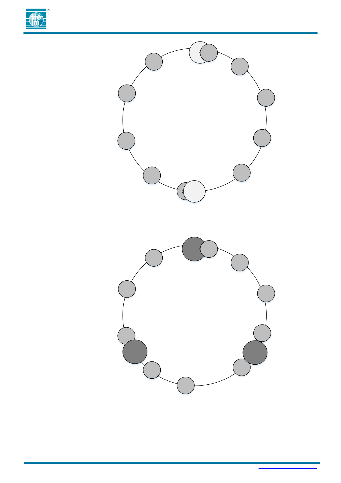
The beacon engine combines the settings of the 10 defined advertisements to create an interleaved
advertisement profile. Below is a diagram showing an example where three advertisements are enabled.
Adv1 is an Eddystone™ URL packet type with an output power of 0dBm at a 1 second interval and a
URL of www.Moving.com set to transmit when the module is moving. Adv2 is a Connectable
advertisement with an output power of -14dBm at a 300ms interval and is always enabled. Adv3 is an
Eddystone™ URL packet type with an output power of -5dBm at a 1.5 second interval and a URL of
www.NotMoving.com set to transmit only when the module is not moving.
The beacon engine combines these three independent advertisement definitions to create appropriate
interleaved advertisement profiles based on the Activity Events detected. The part is in an Inactivity Mode
until an Activity Event is detected and the beacon engine manages interleaving the advertisement profiles
is as shown in the figure below.
Figure 4: Example of three advertisements enabled
Page 12
Preliminary
DATASHEET Ɩ EMBP00
Copyright 2019, EM Microelectronic-Marin SA
EMBP00-DS, Version 0.1, 3-Apr-19
12
www.emmicroelectronic.com
Inactive
Advertisement
Interleaving
Example
ES-UID
Conn
3000ms
Conn
Conn
Conn
Conn
Conn
Conn
Conn
Conn
Conn
ES-UID
Active
Advertisement
Interleaving
Example
ES-URL Conn
3000ms
Conn
Conn
Conn
Conn
Conn
Conn
Conn
Conn
ES-URL
ES_URL
Conn
Figure 5: Example advertisement interleaving in Inactivity Mode
Once an Activity Event is detected, the beacon engine reengages to disable the On When Inactive
advertisement and enables the On When Active advertisements. The resulting interleaved advertisement
for profile in this example is shown below.
When multiple advertisements are running in parallel timing collisions may occur. The firmware will make
priority decisions regarding which advertisement to send next. The advertising interval of one or more
packets is extended by a minimum of 30ms when collisions occurs in order to prevent violation to BLE
advertisement protocols.
Figure 6: Example advertisement interleaving in Activity Mode
Page 13
Preliminary
DATASHEET Ɩ EMBP00
Copyright 2019, EM Microelectronic-Marin SA
EMBP00-DS, Version 0.1, 3-Apr-19
13
www.emmicroelectronic.com
7.1.3.5.1. Activity Mode
Activity Mode is a subset of Beaconing Mode. When advertisements are assigned to this
Advertisement Gating option, the advertisement will only occur after an Activity Event, such as
movement, has been detected and for the duration of time defined by the Activity Timeout.
Advertisements assigned to the Always Enabled advertisement gating option will continue to be
transmitted while in the Activity Mode.
7.1.3.5.2. Inactivity Mode
Inactivity Mode is a subset of Beaconing Mode. When advertisements are assigned to this
advertisement gating option, the advertisement will only occur when not in the Activity Mode.
Advertisements assigned to the Always Enabled advertisement gating option will continue to be
transmitted while in the Inactivity Mode.
BLE Connection
A connection can be initiated from any mode where a connectable advertisement is sent. When a
connection is made, all accelerometer interrupt sources are disabled. If the connection was made from
Configuration or Activity Mode, the correlating timer continues to run while the connection is enabled. If
the corresponding timer expires while the connection is enabled, the timeout event will occur on
disconnect. If the corresponding timer does not expire while the connection is still enabled, the mode that
the connection was initially made in will resume on disconnect. Specific services may initiate a Reset
Event. Refer to Section 7.3 on the supported services for more details. A Reset Event will return the part
to POST.
7.1.4. Mode Transitions
Mode transitions of the EMBP00 are indicated with arrows in the Figure 3. The start and ending mode of
transitions are fixed unless code patches are written and applied. Code patches may be written using the EM
Beacon SDK. The duration of a Configuration Timeout or an Activity Timeout can be redefined using the
SimpleBeacon Configuration Tools. Additionally, the source of the Configuration Event and On/Off Event
can be redefined using the SimpleBeacon Configuration Tools. No source code development is required when
using the SimpleBeacon Configuration Tools.
Configuration Event
A Configuration Event generates a transition from the Beaconing Mode or Warehouse Mode into
Configuration Mode. The Configuration Event may be assigned as defined in Table 9 using the
SimpleBeacon Configuration Tools. No source code development is required when using the
SimpleBeacon Configuration Tools.
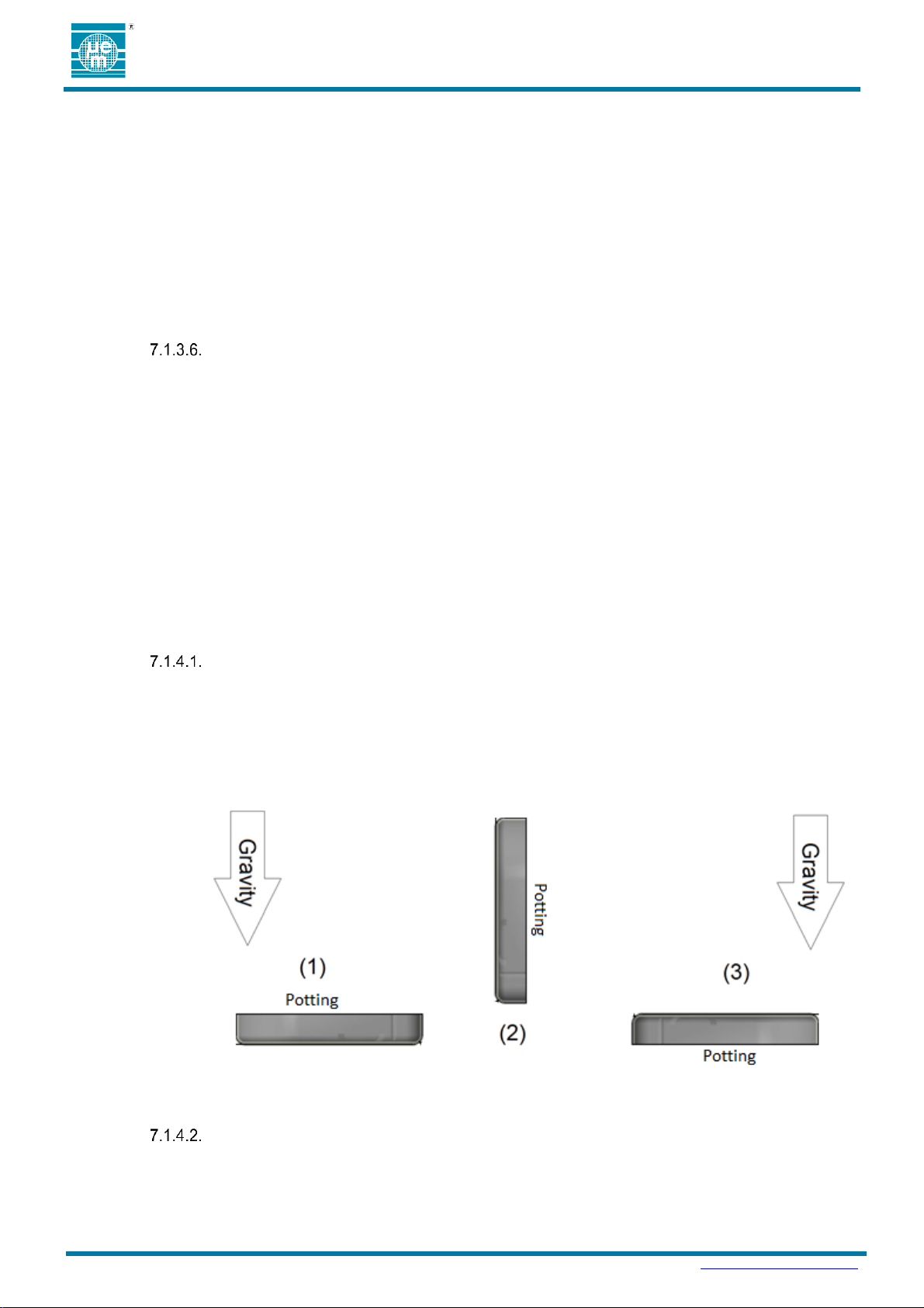
If the Configuration Event is assigned to flip, the event will only be triggered when the module is rotated
from the gravity vector pointing in the negative Z (1) direction to the gravity vector pointed in the positive
Z direction.
Configuration Timeout
On entry into the Configuration Mode, the configuration timer is started. A Configuration Timeout is
generated when that timer expires and initiates a transition from Configuration Mode to the startup mode.
The duration of the Configuration Timeout may be modified with the SimpleBeacon Configuration Tools
as defined in Table 9. No source code development is required when using the SimpleBeacon
Configuration Tools.
Figure 7: Configuration Event Flip Sequence
Page 14

Preliminary
DATASHEET Ɩ EMBP00
Copyright 2019, EM Microelectronic-Marin SA
EMBP00-DS, Version 0.1, 3-Apr-19
14
www.emmicroelectronic.com
Table 11: Accelerometer Configuration Options
Description
Available Options
Default
Units
Output Data Rate (ODR)
Low Power
Settings
Power Down
1.6
12.5
25
50
100
200
High Performance
Settings
Power Down
1.6
12.5
25
50
100
200
400
800
1600
12.5
Hz
Power Mode
Low Power
High Performance
Low Power
-
Low Noise
Enable
Disable
Disabled
-
Filter Bandwidth
Div 2
Div 4
Div 10
Div 20
Div 2
-
Full Scale Range (FSR)
2
4
8
16
2
G
Filter Selection
Low Pass
High Pass
Low Pass
-
Movement Threshold
0 to 63
4
LSB
Movement Duration
0
1
0
Sequential
Samples
On/Off Event
An On/Off Event generates a transition from the Beaconing Mode to Warehouse Mode, from
Configuration Mode to Beaconing Mode and from Warehouse Mode to Beaconing Mode. The On/Off
Event may be modified as defined in Table 7 using the SimpleBeacon Configuration Tools. Refer to
Figure 7 for the sequence required to detect the flip motion. No source code development is required
when using the SimpleBeacon Configuration Tools.
Activity Event
An Activity Event generates a transition from the Inactivity Mode to Activity Mode. The Activity Event may
be assigned as defined in Table 7. Refer to Figure 7 for the sequence required to detect the flip motion.
No source code development is required when using the SimpleBeacon Configuration Tools.
Activity Timeout
An Activity Event generates a transition from the Inactivity Mode to Activity Mode. The Activity Event may
be assigned as defined in Table 7.
On entry into the Activity Mode, the activity timer is started. An Activity Timeout is generated when the
activity timer expires and initiates a transition from Activity Mode to the Inactivity mode. The duration of
the Activity Timeout may be modified with the SimpleBeacon Configuration Tools as defined in Table 9.
No source code development is required when using the SimpleBeacon Configuration Tools.
Reset Event
A Reset Event is initiated by battery insertion, toggling the enable signal from the test bus or from select
BLE services. A Reset Event clears data RAM and returns to the POST state to reinitialize the part.
After a Reset Event a 500ms burst of connectable advertisements will be transmitted from the module.
7.1.5. Accelerometer Configuration
Configuration of key control registers on the accelerometer may be modified from the SimpleBeacon
Configuration Tools. The configurable options are listed in Table 11. Full descriptions of the parameter are
available in the STM LIS2DWL datasheet (see DocID029682 Rev4). Additional details regarding the impact
on the operating behavior, consumption and performance of the device can be found in the accelerometer
datasheet.
Page 15

Preliminary
DATASHEET Ɩ EMBP00
Copyright 2019, EM Microelectronic-Marin SA
EMBP00-DS, Version 0.1, 3-Apr-19
15
www.emmicroelectronic.com
2
3
Flip 4D/6D
4D Detection
6D Detection
6D
-
6D Threshold
50
60
70
80
80
Degrees
6D Low Pass Filter
Enable
Disable
Enabled
-
Tap Shock X Threshold
0 to 31
9
LSB
Tap Shock Y Threshold
0 to 31
9
LSB
Tap Shock Z Threshold
0 to 31
9
LSB
Tap Shock Time
4
8
12
16
16
Samples
Tap Quiet Time
2
4
6
8
2
Samples
Double Tap Latency
16
32
48
64
80
96
112
128
144
160
176
192
208
224
240
256
128
Samples
Tap Axii
X Axis
Y Axis
Z Axis
All Enabled
-
Freefall Duration
0-63
3
Samples
Freefall Threshold
5
7
8
10
11
13
15
16
10
LSB
Modifications to the accelerometer settings can have a dramatic impact on battery life. Consult the STM
datasheet to calculate the full impact of changes to the accelerometer settings.
ADVERTISEMENTS
7.2.1. Device Address
7.2.2. Advertising Channels
Each EMBP00 has a unique factory-assigned address. The first 3 octets of the device address are the EM
Microelectronic OUI assigned address from the IEEE 802 committee and subject to change without notice.
The last 3 octets of the device address are uniquely assigned by EM Microelectronic. All advertisements
enabled in the Beaconing and Configuration Modes share the same Device Address.
The device address to be used may be modified with the SimpleBeacon Configuration Tools. If the address
00:00:00:00:00:00 is entered, then the factory-assigned address will be used.
Advertisements are transmitted on channel 37, 38 and 39. Firmware options to disable up to two of the three
advertisement channels for non-connectable advertisements are available. The option to disable the
advertisement channels is unavailable in the standard release of the SimpleBeacon Configuration Tools. The
Page 16

Preliminary
DATASHEET Ɩ EMBP00
Copyright 2019, EM Microelectronic-Marin SA
EMBP00-DS, Version 0.1, 3-Apr-19
16
www.emmicroelectronic.com
Table 12: RSSI Table
Tx Power Level
(dBm)
RSSI Table Entry
(dBm at 1m)
6.2
-55
4.6
-57
2.5
-59
0.4
-61
-1.4
-63
-2.6
-64
-4
-66
-5.5
-67
-6.9
-68
-8.4
-70
-9.9
-71
-11.4
-73
-13.1
-75
-14.6
-76
-16.4
-78
-17.9
-79
-29
-91
-33.5
-95
features can be made available on request in SimpleBeacon Configuration Tools. Disabling of advertisement
channels is not compliant with Bluetooth specifications and compatibility with other BLE technology cannot be
guaranteed when channels are disabled.
7.2.3. RSSI Table
The Eddystone™, iBeacon™ and altBeacon™ packet types include a one byte signed value that is used to
communicate the signal strength of the packet being transmitted. This byte is retrieved from the RSSI Table in
the EMBP00. The beacon engine will automatically retrieve the setting that correlates to the selected output
power setting for the advertisement. Default values are assigned using the calibration procedure defined by
Apple™ and an iPhone 4S™. The default settings are as defined in Table 12.
The RSSI Table values may be modified using the SimpleBeacon Configuration Tools.
7.2.4. Connectable Advertisement
These Bluetooth advertising packets are connectable, undirected advertising events (ADV_IND) which follow
the GAP specification according to the Bluetooth Specification V5.0, Volume 3, Part C, Section 11.
The friendly name used in the connectable advertisement may be redefined using the SimpleBeacon
Configuration Tools. If the friendly name is left blank in the SimpleBeacon Configuration Tools, the name is
automatically generated from the device address. Additionally the special character “$” in the friendly name
will be replaced with the lowest nibble in hex of the device address.
The default friendly name is EM-$$$$$$.
7.2.5. Non Connectable Advertisements
These Bluetooth advertising packets are non-connectable, undirected advertising events
(ADV_NONCONN_IND) which follow the GAP specification according to the Bluetooth Specification V5.0,
Volume 3, Part C, Section 11.
iBeacon™ Format
The format of the iBeacon™ packet is described in the following specification: Proximity Beacon
Specification Release R1 Draft D1, which can be obtained from Apple, Inc.
The UUID, Major ID and Minor ID used in the iBeacon™ advertisement may be redefined using the
SimpleBeacon Configuration Tools. If the UUID is set to 0, the default UUID of 699EBC80-E1F3-11E39A0F-0CF3EE3BC012 is used. If the Major ID are set to 0, the Major ID from the second lowest two
bytes of the device address. If the Minor ID are set to 0, the Minor ID from the lowest two bytes of the
device address. For example, for a device with address: 0C:F3:EE:AA:BB:CC. If the Major ID is set to 0,
the transmitted Major ID will be 0xEEAA. If the Minor ID is set to 0, the transmitted Minor ID will be
0xBBCC
Page 17

Preliminary
DATASHEET Ɩ EMBP00
Copyright 2019, EM Microelectronic-Marin SA
EMBP00-DS, Version 0.1, 3-Apr-19
17
www.emmicroelectronic.com
Eddystone™ UID and URL
Refer to the Eddystone™ specifications available on GitHub for details on the payload of an Eddystone™
URL and Eddystone™ UID packet.
The URL, UID Namespace and UID Instance used in the Eddystone™ advertisement may be redefined
using the SimpleBeacon Configuration Tools. If the URL parameter is left blank in the SimpleBeacon
Configuration Tools, the default URL of emdeveloper.com is used. If the UID Namespace is set to 0 in the
SimpleBeacon Configuration Tools, the default UID Namespace value is 699E-BC80-E1F3-11E3-9A0F. If
the UID Instance is set to 0 in the SimpleBeacon Configuration Tools, the default UID Instance value is
the device address.
AltBeacon™ Formats
Refer to the AltBeacon™ specifications available on GitHub for details on the payload of an AltBeacon
packet.
The GUID, Major ID and Minor ID used in the altBeacon™ advertisement may be redefined using the
SimpleBeacon Configuration Tools. If the GUID parameter is set to 0, the default GUID of 699EBC80E1F3-11E3-9A0F-0CF3EE3BC012 is used. If the Major ID and Minor ID parameters are both set to 0 in
the SimpleBeacon Configuration Tools, the Major ID and Minor ID are extracted from the lowest 4 bytes
of the device address.
User Defined Format
A fixed payload of up to 31 bytes may be defined by the user. Compliance with BLE advertising
specification and requirements are the responsibility of the user to maintain compatibility with third party
BLE equipment.
SUPPORTED BLE SERVICES
7.3.1. Firmware Over The Air (FOTA) Service
Service UUID: 00007001-0000-0041-4c50-574953450000
The EM9304 Firmware Over-The-Air (FOTA) service allows the user to upload new configuration
and code containers onto the EM9304. Containers may be uploaded into one of two memories:
IRAM or OTP. In addition, the containers stored on the EM9304 may be listed and invalidated
through the FOTA profile. The FOTA profile can also reset the part as well as turn off IRAM.
Details about the OTP, IRAM and patching are available in the EM9304 datasheet.
The Implementer’s Guide for the EM9304 FOTA service is available through the development
support forums.
The Invalidate command of the Memory Access Control Point Characteristic in the FOTA service is
used to transition the part from Factory parameters to deployed parameters.
7.3.2. Beacon Information Service
Service UUID: F4000A80-DE94-078F-E311-35B1EE4FDB15
The Beacon Information Service is designed to allow users to read the current configuration status
of the module.
The protocol is a command-response. To use the service, the remote app writes a command to the
Command Characteristic and reads the response from the Data Characteristic. Refer to the EM
Beacon SDK for more details on the protocol.
Command Characteristic
Characteristic UUID: F1000A80-DE94-078F-E311-35B1EE4FDB15
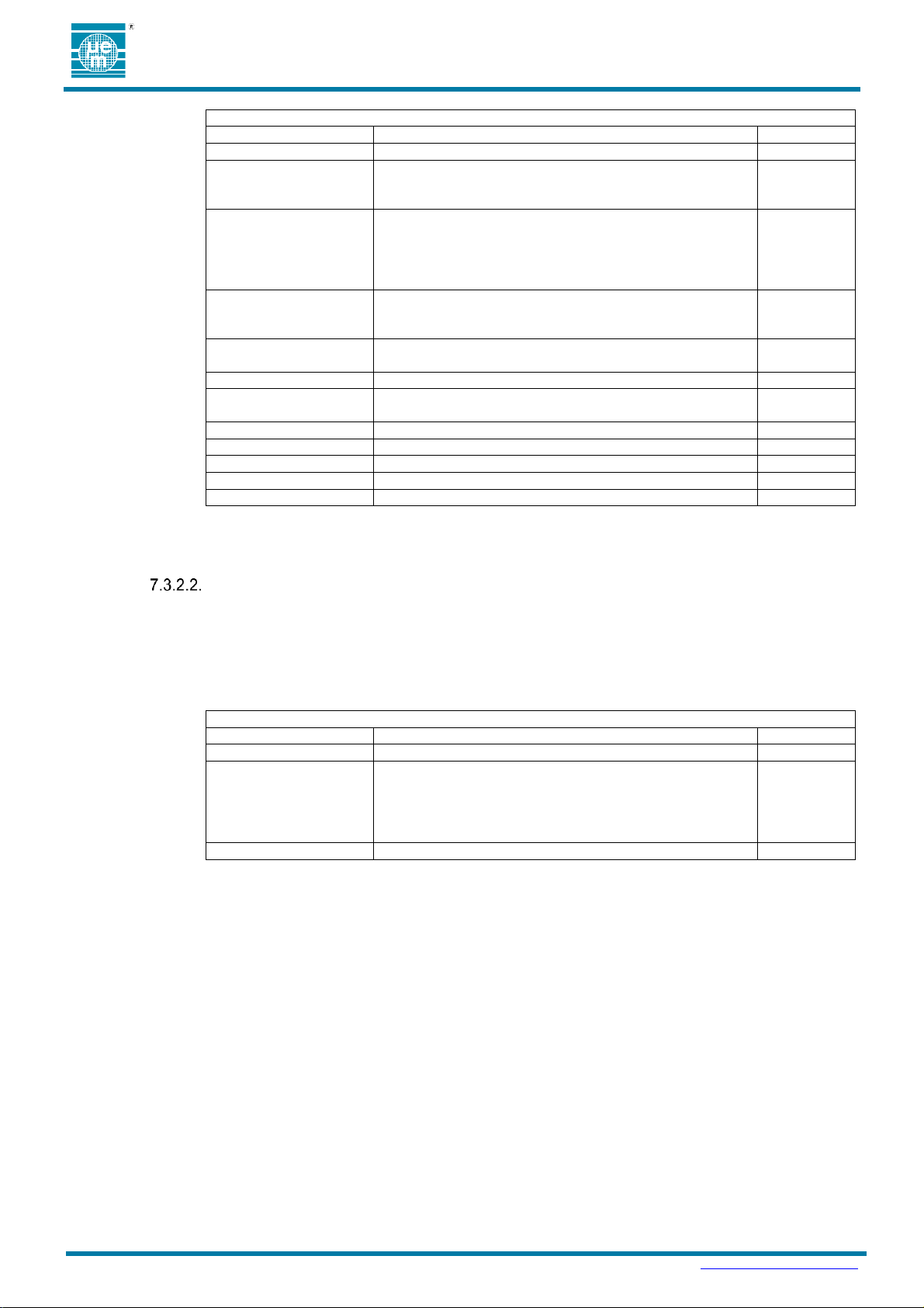
The Command Characteristic is a write-only characteristic. The complete list of commands is shown in
Table 13.
Page 18
Preliminary
DATASHEET Ɩ EMBP00
Copyright 2019, EM Microelectronic-Marin SA
EMBP00-DS, Version 0.1, 3-Apr-19
18
www.emmicroelectronic.com
Table 13: Beacon Information Service Commands
Command
Description
Hex Code
Get Version
Request for the firmware version of the application.
0x01
Get Device
Configuration
Request for the settings of the parameters in the Device
Configuration tab of the SimpleBeacon Configuration
Tools.
0x02
Get Advertising
Configuration <n>
Request for the settings of the parameters in the Advert-x
tab of the SimpleBeacon Configuration Tools.
POST Advertisement: n=0
Configuration Mode Advertisement: n=1
Advertisement 1-10: n=16-25
0x03
Get Accelerometer
Configuration
Request for the settings of the parameters in the
Accelerometer Configuration tab of the SimpleBeacon
Configuration Tools.
0x04
Get RSSI Table
Request for the settings of the parameters in the RSSI tab
of the SimpleBeacon Configuration Tools.
0x05
Get Device Address
Request for the factory assigned Device Address
0x06
Get Diagnostic Code
Request usage and diagnostic information in event of
failure.
0x07
Get Protocol ID
Request identifier structure
0x08
Generate On/Off Event
Issue and On/Off Event
0x0B
Get Factory Marker
Read the factory marker
0x0C
Get VBAT
Read battery voltage (100mV resolution)
0x0D
Get Diagnostics
Read Usage and diagnostic info
0x0E
Table 14: Beacon Information Data Characteristic
First Data Byte
Description
Hex Code
Error Response
A detailed error code and additional data if any follows.
0x80
Configuration Patch
This response can be saved as a binary file and used as a
9304 patch file. The beacon produces responses in this
format when the request is for the Device Configuration,
Advertisement Configuration, Accelerometer Configuration,
Factory Marker or RSSI Table.
0x33
Command Echo
Echo of the command code that generated the data
All Others
The format of the command is
<Command> <Optional Parameter> <Bytes to Follow> <Optional Data>
Data Characteristic
Characteristic UUID: F2000A80-DE94-078F-E311-35B1EE4FDB15
The Data Characteristic is a read-only characteristic. The format of the return is either the requested data
or an error code. The first byte of the return is unique and indicates the type of response as defined in
Table 14.
7.3.3. Device Information Service
SIG Service Assigned Number: 0x180A
The Device Information Service is the standard service defined by the Bluetooth SIG. This service exposes
manufacturer information about a device. The Device Information Service is instantiated as a Primary Service.
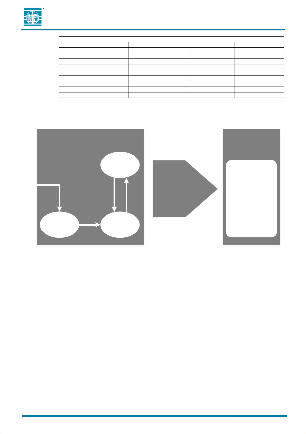
Only one instance of the Device Information Service is exposed on a device. The service defines 9
characteristics. Usage for the 9 characteristics are detailed in Table 15.
Page 19
Preliminary
DATASHEET Ɩ EMBP00
Copyright 2019, EM Microelectronic-Marin SA
EMBP00-DS, Version 0.1, 3-Apr-19
19
www.emmicroelectronic.com
Table 15: Device Information Service
Characteristic Name
Default
Configurable
Assigned Number
Manufacturer Name
EM Microelectronic
Yes
0x2A29
Model Number
blank
Yes
0x2A24
Serial Number
Factory MAC Address
No
0x2A25
Hardware Revision
Unused
No
0x2A27
Firmware Revision
5A.00.01.00.00
No
0x2A26
Software Revision
Unused
No
0x2A28
System ID
Unused
No
0x2A23
Regulatory Certification List
Unused
No
0x2A2A
PnP ID
Unused
No
0x2A50
Field Operating
Conditions
Operating conditions for
units in installed in the field until
product End of Life
Factory Operating Conditions
Operating conditions for up to 1 year in environment such as
assembly, shipping, and storage
with negligible depletion of battery life
Beaconing Mode
Reset
Power On
Self Test
Warehouse
Mode
Adverts OFF
Configuration
Mode
Connectable Adverts
1 Min Timeout
Flip
Deployment
Operation
- External BLE Master Connect s
- Load Field Operating Conditions
- Disconnect
8. TYPICAL FIELD ACTIVATION
As noted in Section 7, units are shipped in Factory Operating Conditions for activation in the field to convert to Deployment
Operating Conditions.
Refer to the EM Beacon Configuration Tools for mobile and PC support tools to support deployment and development of
deployment tools.
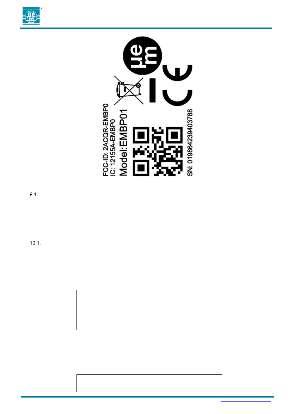
9. UNIT LABEL
The label has the following contents:
Model: EMBP00
Unique Serial Number
FCC-ID: 2ACQR-EMBP0
IC: 12155A-EMBP0
Figure 8: Configuration Event Flip Sequence
WEEE Marking
CE Marking
QR Code containing the unique serial number
EM Microelectronic logo
Page 20
Preliminary
DATASHEET Ɩ EMBP00
Copyright 2019, EM Microelectronic-Marin SA
EMBP00-DS, Version 0.1, 3-Apr-19
20
www.emmicroelectronic.com
EM P/N:
Mfg date:
Module Lot Nr:
Qty:
EM P/N:
Mfg date:
SERIAL NUMBER
The serial number is generated by reading the device address of EMBP00, reversing the byte order, and printing the
number in decimal form.
For example:
Device Address: 0x0CF3EE001122 corresponds to Serial Number: 19864239403788
10. PACKING AND LABELING
FINISHED PRODUCT
10.1.1. Inner Packing
EMBP00 beacons are packed in custom antistatic trays.
Only one tray per box can have parts from 2 different product lots.
Tray size is 300 x 261 x 38 mm.
Number of parts per tray is 100pcs.
There are 4 trays per stack, excluding cover tray.
A label is applied on each stack. The minimum information on the label is specified in Figure 10.
Figure 9: Unit label
10.1.2. External Packing
Tray stacks are packed in cardboard box.
Quantity of parts per box is 800 pcs (2 tray stacks).
Box dimensions are 37 x 55 x 43 cm.
A label is applied on each box. The minimum information on the label is specified in Figure 11.
Figure 10: Packing label information
Page 21
Preliminary
DATASHEET Ɩ EMBP00
Copyright 2019, EM Microelectronic-Marin SA
EMBP00-DS, Version 0.1, 3-Apr-19
21
www.emmicroelectronic.com
Module Lot Nr:
Qty:
Weight:
11. ENVIRONMENTAL SAFETY
RESTRICTION OF HAZARDOUS SUBSTANCES (ROHS)
EM Product is compliant with the EU RoHS Directive 2011/65/EU and its amendments, including the
amendment 2015/863/EU, on the restriction of the use of certain hazardous substances in electrical and
electronic equipment, and does not contain any of the substances listed below above the concentration levels
specified in the Directive 2015/863/EU:
Lead (Pb): <1000 ppm
Mercury (Hg): <1000 ppm
Cadmium (Cd): <100 ppm
Hexavalent Chromium (Cr VI) <1000 ppm
Polybrominated Biphenyls (PBB): <1000 ppm
Polybrominated Diphenyl Ethers (PBDE): <1000 ppm
Bis(2-ethylhexyl) Phthalate (DEHP) : <1000 ppm
Butyl benzyl Phthalate (BBP): <1000 ppm
Dibutyl Phthalate (DBP): <1000 ppm
"HALOGEN FREE" - IEC 61249-2-21:2003.
EM Product is compliant with the "Halogen Free" - IEC 61249-2-21:2003 Standard and does not contain
brominated and chlorinated compounds above the threshold level for each homogeneous material within the
Product.
REACH AND SVHC LIST
EM Product is compliant with the EU Regulation 1907/2006 (REACH) and the SVHC list (Substances of Very
High Concern). The SVHC must be below the limit of 0.1% set by REACH Article 33, as specified in the
Candidate list published by ECHA (European Chemical Agency)
https://www.echa.europa.eu/web/guest/candidate-list-table
EM Product is compliant with the restrictions imposed by the 76/769/EEC European Directive and which have
been included in the Annex XVII of REACH.
PRODUCT HARDWARE RECYCLING (WEEE)
The Directive 2012/19/EU on Waste Electrical and Electronic Equipment (WEEE) aims to reduce the waste
arising from electrical and electronic equipment, and improve the environmental performance of everything
involved in the life cycle of electrical and electronic equipment.
Instructions for Disposal of Waste Equipment by Users in Private
Households
This symbol on the product or on its packaging indicates that this product
must not be disposed of with your other household waste. Inappropriate
disposal may be harmful. Instead, it is your responsibility to dispose of your
waste equipment by handing it over to a designated collection point for the
recycling of waste electrical and electronic equipment. The separate
collection and recycling of your waste equipment at the time of disposal will
help to conserve natural resources and ensure that it is recycled in a
manner that protects human health and the environment. For more
information about where you can drop off your waste equipment for
recycling, please contact your local city office, your household waste
disposal service or the sales point where you purchased the product.
Responsibilities
EM is committed to meeting the requirements of the European Union’s WEEE Directives.
However, the System Integrator of EM Product has the responsibility for the collection and recycling of the
Beacon after its end of life.
Diisobutyl Phthalate (DIBP): <1000 ppm
Chlorine (Cl): <900 ppm
Bromine (Br): <900 ppm
Total halogens (limited to Br + Cl): <1500 ppm
Figure 11: Panel packing label information
Page 22

Preliminary
DATASHEET Ɩ EMBP00
Copyright 2019, EM Microelectronic-Marin SA
EMBP00-DS, Version 0.1, 3-Apr-19
22
www.emmicroelectronic.com
EM Customer can send back the collected EM Product to EM at DAP conditions (Delivery at Place). If the
Lithium batteries are included in the air freight shipment, IATA DGR (Dangerous Goods) rules are to be
applied.
Specifics on battery
The Directive 2012/19/EU does apply to batteries and requires their removal from the electronic equipment
and their separate collection. Once removed from equipment, used batteries are governed by the Batteries
Directive 2006/66/EC.
Page 23
Preliminary
DATASHEET Ɩ EMBP00
Copyright 2019, EM Microelectronic-Marin SA
EMBP00-DS, Version 0.1, 3-Apr-19
23
www.emmicroelectronic.com
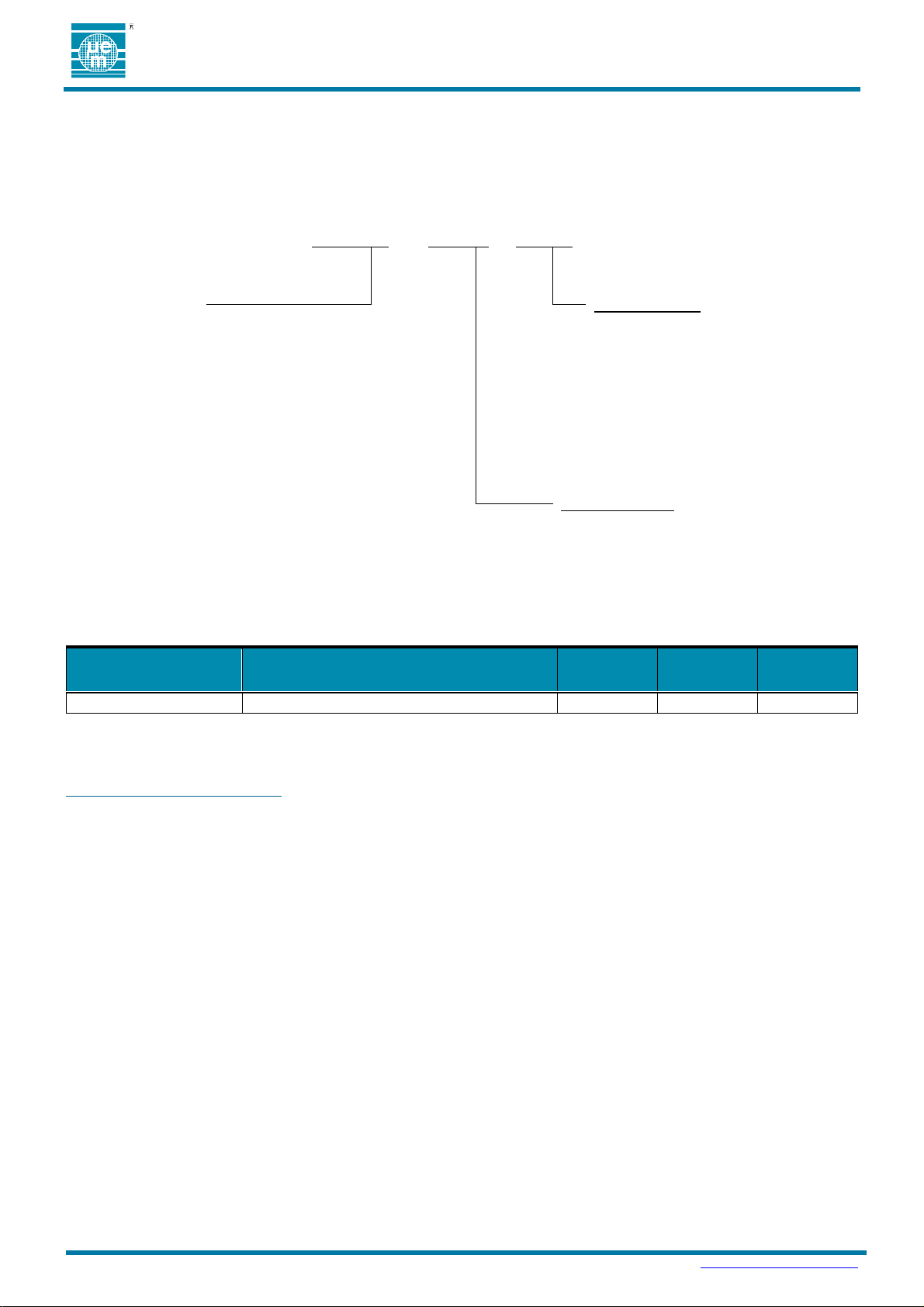
EMBP00
- F171
-
H2100
Base Part Number
Housing Version:
EMBP00: Standard Version
Hwxyz: housing, color, label, battery
w – housing color
x – marking layout
y – open
z – open
H3100: Blue Cup; EM Marking
Firmware Version:
F171: Standard Product FW V1.1
Other: Assigned by EM
ORDER NUMBER
DESCRIPTION
CONTAINER
UNITS PER
CONTAINER
MINIMUM
ORDER
QUANTITY
EMBP00-F171-H3100
Standard Accelerometer Beacon
Box
800
800
12. ORDERING INFORMATION
The EMBP00 is available as a finished product with full FCC, IC, and CE certification. The EMBP00 ordering information is
shown in Figure 12 and the order numbers are shown in Table 16.
Figure 12: EMBP00 Ordering Information
Table 16: EMBP00 Related Order Nu mbers
13. CONTACT INFORMATION
Inquiries for lead-times, quotes, orders:
14. REFERENCE DOCUMENTS
EM9304 Device Specification
LIS2DWL Device Specification
Bluetooth Specification V5.0
Page 24

Preliminary
DATASHEET Ɩ EMBP00
Copyright 2019, EM Microelectronic-Marin SA
EMBP00-DS, Version 0.1, 3-Apr-19
24
www.emmicroelectronic.com
EM Microelectronic-Marin SA (“EM”) makes no warranties for the use of EM products, other than those expressly contained in EM's applicable
General Terms of Sale, located at http://www.emmicroelectronic.com. EM assumes no responsibility for any errors which may have crept into
this document, reserves the right to change devices or specifications detailed herein at any time without notice, and does not make any
commitment to update the information contained herein.
No licenses to patents or other intellectual property rights of EM are granted in connection with the sale of EM products, neither expressly nor
implicitly.
In respect of the intended use of EM products by customer, customer is solely responsible for observing existing patents and other intellectual
property rights of third parties and for obtaining, as the case may be, the necessary licenses.
Important note: The use of EM products as components in medical devices and/or medical applications, including but not limited to,
safety and life supporting systems, where malfunction of such EM products might result in damage to and/or injury or death of
persons is expressly prohibited, as EM products are neither destined nor qualified for use as components in such medical devices
and/or medical applications. The prohibited use of EM products in such medical devices and/or medical applications is exclusively at
the risk of the customer.
Bluetooth is a trademark of the Bluetooth SIG. iPad and iPhone are trademarks of Apple Inc., registered in the U.S. and other countries. Android is a trademark of Google Inc. Google Play is a
trademark of Google Inc. Other product and company names mentioned herein may be trademarks of their respective companies.
 Loading...