

Page 1
EM MICROELECTRONIC - MARIN SA
Copyright 2018, EM Microelectronic-Marin SA
EMBC22_user_manual_v3, Version 1.0 , 25-Sep-18
1
www.emmicroelectronic.com
EMBC22 User Manual
Low-Energy
Proximity Beacon
With Accelerometer
FEATURES
Ɩ Supports all popular beacon formats such as iBeacon™,
Eddystone™, AltBeacon™, and compatible with Quuppa
Intelligent Locating System™
Ɩ Unique iBeacon ID and scannable QR-code come standard
Ɩ Accelerometer can be used to activate beaconing on
actions such as movement, or gestures
Ɩ Secure over-the-air updates possible with all major mobile
platforms in the field
Ɩ Multiple interleaved packet types with customizable
parameters:
Ɩ Packet types, including custom packet type
Ɩ Device name, address, manufacturer name, model
number, HW/SW revision
Ɩ UUID, Major/Minor ID, UID or URL
Ɩ Beacon interval, Transmitter power
Ɩ Accelerometer function and sensitivity
Ɩ Firmware can be customized and loaded at production for
large quantity orders
Ɩ Long battery lifetime
Ɩ Over 4 year battery lifetime at 0dBm and 1sec intervals,
when active 8 hours/day
Ɩ Battery lifetime calculator available
Ɩ Long range
Ɩ Up to 200m line-of-sight (LOS) at maximum output power
Ɩ Push button with LED feedback (red and green)
Ɩ Weatherproof Enclosure (IP-64 Rating)
Ɩ Key-fob or custom accessories available
Ɩ Available with an optional connector for
Ɩ Software development
Ɩ Adding sensors
Ɩ Alternate power source
Ɩ Available as PCB module with CR2032 battery standard
Ɩ Allows support of other Li coin cell batteries (i.e. CR2016,
CR2450, and CR2477) and custom housing designs
Ɩ Temperature range from -20C to +60C
Ɩ Modular Bluetooth V5.0, FCC, IC, and CE certified, RoHS
and REACH compliant
Ɩ Made with Swatch Electronics Group technologies:
Ɩ EM Microelectronic EM9304 Bluetooth V5.0 SOC
Ɩ Renata CR2032 coin-cell battery
Ɩ Micro Crystal 32.768kHz crystal
DESCRIPTION
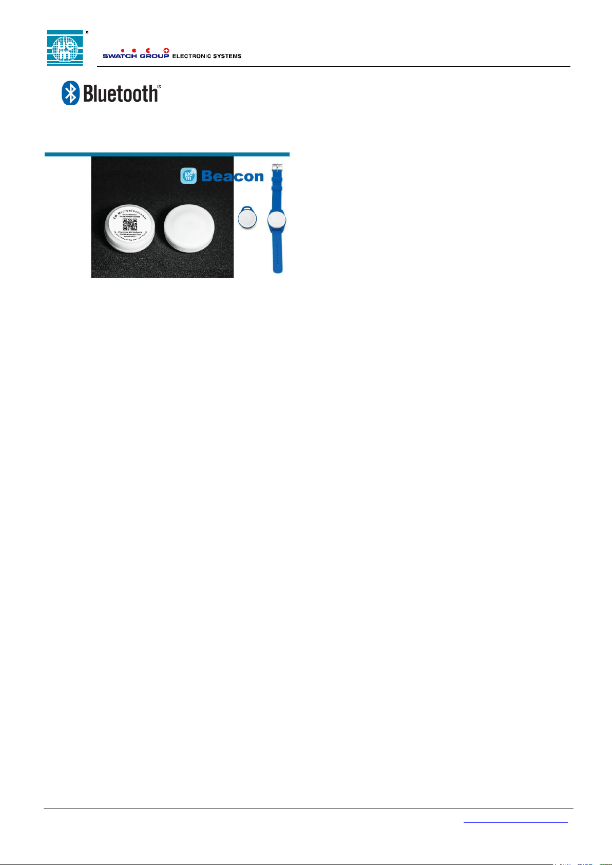
The EMBC22 is a high-performance, customizable
Bluetooth V5.0 low energy proximity beacon with an
accelerometer for tracking objects that move. Similar to the
EMBC02, the EMBC22 comes in simple, easy to use coinshape housing, and is now powered by the EM9304, the
world’s lowest power Bluetooth IC.
New features include:
Longer life from a CR2032 battery
Longer range (up to 200m LOS)
Over-the-air configurability
Multiple interleaved packet types
Modular RF certification
Optional connector for sensors or power source
The EMBC22 is compatible with all major beacon formats
including iBeacon™, Eddystone™, AltBeacon™ and
compatible with Quuppa Intelligent Locating System™. The
beacon is fully customizable over the air or in production.
For example, the following parameters can be easily
modified:
Packet types, including custom packet type
Device name, address, manufacturer name, model
number, HW/SW revision
UUID, Major/Minor ID, UID or URL
Beacon interval, Transmitter power
Accelerometer function and sensitivity
The EMBC22 can be shipped pre-programmed with custom
firmware or custom parameters and can be securely
updated in the field with over-the-air programming from a
mobile device (all major iOS® and Android™ devices
supported).
The EMBC22 accelerometer can be used to implement
efficient and low-energy algorithms for various applications.
The accelerometer can be used to activate beaconing on
movement, or gestures, for example. When not active, the
beacon dissipates minimal energy.
The EMBC22 can be stored in off mode without significantly
degrading the battery lifetime. When active for 8 hours per
day and configured for 0dBm output power and 1 second
advertising intervals, the battery lifetime is more than 4
years.
The EMBC22 can be delivered in any quantity with
guaranteed unique ID. A 2D unique serial number is printed
on the beacon housing for optical scanning.
The EMBC22 is also available in PCB module format
without housing. The module comes with the switch and
battery holder. The beacon comes standard with a Renata
CR2032/ 225mAh battery. Other Renata Lithium primary
batteries such as CR2016/90mAh, CR2450/540mAh and
CR2477/950mAh can also be accommodated.
The EMBC22 comes in a waterproof housing, and operates
over a -20C to +60C temperature range. The EMBC22 is
modular Bluetooth V5.0, FCC, IC, and CE certified, RoHS
and REACH compliant.
420005-A01, 2.0
Page 2
EMBC22 user manual
Copyright 2018, EM Microelectronic-Marin SA
EMBC22_user_manual_v3, Version 1.0 , 25-Sep-18
2
www.emmicroelectronic.com
TABLE OF CONTENTS
1. 1. GENERAL DESCRIPTION ............................................................................................................................ 3
2. ENVIRONMENTAL AND STORAGE CONDITIONS ......................................................................................... 4
3. PRODUCT DESCRIPTION ................................................................................................................................ 4
EMBC22 APPLICATION TO A FINISHED BEACON ............................................................................................ 4
PCB .......................................................................................................................................................... 4
4. MECHANICAL ................................................................................................................................................... 5
PUSH BUTTON ............................................................................................................................................ 5
LED........................................................................................................................................................... 5
5. ELECTRICAL ..................................................................................................................................................... 5
HANDLING PROCEDURES AND ABSOLUTE MAXIMUM RATINGS ......................................................................... 5
GENERAL OPERATING CONDITIONS .............................................................................................................. 5
ELECTRICAL CHARACTERISTICS ................................................................................................................... 6
REGULATORY ............................................................................................................................................. 6
5.4.1. USA-FCC .................................................................................................................................. 6
5.4.2. Canada-IC ................................................................................................................................. 6
5.4.3. CE ............................................................................................................................................. 6
5.4.4 REGULATORY INFORMATION USA ........................................................................................................... 7
5.4.4.1 Class B device notice ............................................................................................................... 7
5.4.4.2 RF exposure safety ................................................................................................................... 7
5.4.4.3 Permitted Antenna .................................................................................................................... 7
5.4.4.4 Labelling Requirements for the Host Device ................................................................................ 7
5.4.5 REGULATORY INFORMATION CANADA ................................................................................................... 7
5.4.5.1 RF Exposure Safety ..................................................................................................................... 8
5.4.5.2 Permitted Antenna ....................................................................................................................... 8
5.4.5.3 CAN ICES-3 (B)/NMB-3(B) .......................................................................................................... 8
5.4.5.4 Labelling Requirements for the Host Device ................................................................................ 8
6 FIRMWARE ........................................................................................................................................................ 9
6.4 STATE MACHINE ......................................................................................................................................... 9
6.4.5 State Machine Configuration Options ....................................................................................... 9
6.4.6 Hardware Features ................................................................................................................. 10
6.4.7 Operating Modes .................................................................................................................... 10
6.4.8 Mode Transitions .................................................................................................................... 13
6.4.9 Accelerometer Configuration .................................................................................................. 14
6.5 ADVERTISEMENTS..................................................................................................................................... 15
6.5.5 Device Address ....................................................................................................................... 15
6.5.6 Advertising Channels .............................................................................................................. 15
7 LABEL .............................................................................................................................................................. 16
7.4 SERIAL NUMBER ....................................................................................................................................... 16
8 PACKING AND LABELING ............................................................................................................................. 16
8.4 FINISHED PRODUCT .................................................................................................................................. 16
8.4.5 Inner Packing .......................................................................................................................... 16
8.4.6 External Packing ..................................................................................................................... 16
9 ACCESSORIES ............................................................................................................................................... 16
10 ENVIRONMENTAL SAFETY ........................................................................................................................... 16
11 ORDERING INFORMATION ............................................................................................................................ 17
12 CONTACT INFORMATION .............................................................................................................................. 17
13 REFERENCE DOCUMENTS ........................................................................................................................... 17
420005-A01, 2.0
Page 3

EMBC22 user manual
Copyright 2018, EM Microelectronic-Marin SA
EMBC22_user_manual_v3, Version 1.0 , 25-Sep-18
3
www.emmicroelectronic.com
1. GENERAL DESCRIPTION
The EMBC22 is a 2.4 GHz RF electronic beacon with proximity capability, compatible with most common beacon standards
with a low cost design for mass production, and includes a low-power accelerometer for activation features.
Over-the-air configurable:
Up to 10 advertisements running parallel and uniquely defined
o Industry Standard Packet Types
iBeacon™
altBeacon™
Eddystone™ UID, TLM, and URL
User defined
o Advertisement interval
From 30ms to 18hrs
o 17 Output Power Steps
From +6dBm to -34dBm
o Conditional Advertising Options
Continuous Advertising
Advertising On Activity
Advertising On Inactivity
Simple state machine
o User defined events to enter Configuration Mode
Options for: Short button press, long button press or accelerometer flip
o User defined events to toggle between Warehouse and Beaconing Mode
Options for: Short button press, long button press or accelerometer flip
o User configurable timeouts from the Configuration and Active Mode
From 100ms to 1.8hrs
o User defied events to activate Activity Mode
Motion, tap, double tap, freefall, flip or short button press
o Lockable
Flexible accelerometer settings
o Control of sensitivity, sampling rates, duration, etc. settings
Long Range:
100m LOS at 0dBm
200m LOS at max output power
Long Battery Life:
Replaceable CR2032 Li 3V battery
Up to 10 years storage life
Normal Operating Conditions:
-20 to +60 C
Weather proof (IP-64 rating)
Small and Lightweight:
30mm diameter x 10mm disk
7 grams
Certifications:
Environmental: RoHS, REACH, Halogen Free
RF: FCC, IC, CE
Compatible With:
Bluetooth Smart Ready Devices
Most Common Beacon Standards
EMBC Configuration Tool
A free smart phone and tablet application for:
iOS
Android
Included Hardware:
A white plastic enclosure
A push button for mode changes
A green and red LED for user feedback
A permanent label with a unique serial
number and QR Code
Multiple Delivery Formats:
Finished product
Custom Firmware
Custom Housing
PCB Only
Optional Mounting Accessories:
Key-fob
Other options possible (wall-mount, wrist-
band are available upon demand)
Multiple Battery Sizes:
Standard in EMBC22 housing is
CR2032/225mAh battery
CR2016/90mAh, CR2450/540mAh,
CR2477/950mAh (housing available upon
demand)
Fully Customizable:
Development kit available
Adjustable parameters
Modifiable firmware
420005-A01, 2.0
Page 4

EMBC22 user manual
Copyright 2018, EM Microelectronic-Marin SA
EMBC22_user_manual_v3, Version 1.0 , 25-Sep-18
4
www.emmicroelectronic.com
Table 1: Environmental and storage conditions
Module operating temperature
and humidity range
-20°C to 60°C and 0 to 90% RH
Weatherproof
Module can be used in outdoor conditions.
It is rated IP64 according to CEI 60529.
Module storage temperature
and humidity range
Modules must be stored in original EM packing at Temp=25°C±5°C / RH 30-45%.
1. ENVIRONMENTAL AND STORAGE CONDITIONS
The operating and storage conditions are listed in Table 1.
2. PRODUCT DESCRIPTION
3.0 INTRODUCTION
The EMBC22 is a single PCB BLE solution that can be used with many housing types or battery
combinations. An example of the single modular transmitter module applied to a beacon application is shown
below.
EMBC22 APPLICATION TO A FINISHED BEACON
The finished product outline dimensions are shown in Figure 1 for the CR2032 version only. Dimensions for housings
for other battery sizes available upon request.
Figure 1: EMBC22 application to beacon
PCB
The EMBC22 accelerometer beacon module PCB is shown in Figure 2 with a 26mm diameter. An optional
SlimStackTM connector (Molex PN 5037761610) can be used for software development (JTAG access), for connection
to a daughter board with sensors for example, or to connect to a different power source such as a battery pack. The
standard version comes with a CR2032 replaceable battery and battery holder. Other battery sizes such as CR2016,
CR2450, or CR2477 batteries can also be accommodated.
420005-A01, 2.0
Page 5

EMBC22 user manual
Copyright 2018, EM Microelectronic-Marin SA
EMBC22_user_manual_v3, Version 1.0 , 25-Sep-18
5
www.emmicroelectronic.com
Table 2: Absolute maximum ratings
Parameter
Min
Max
Unit
Supply Voltage VCC - VSS
-0.3
3.8
V
Table 3: General Operating Conditions
Parameter
Min
Typ
Max
Unit
Supply Voltage (VCC)
2.0
3.0
3.6
V
Temperature Range
-20
25
+60
°C
Figure 2: Accelerometer beacon module PCB with connector
3. MECHANICAL
PUSH BUTTON
The push button is activated with a firm press. It is designed so that it cannot be activated accidentally.
LED
The green and red LEDs are visible through the plastic enclosure under indoor lighting conditions. LEDs are used to
indicate the operating mode of the beacon.
4. ELECTRICAL
CAUTION. RISK OF EXPLOSION IF BATTERY IS REPLACED BY AN INCORRECT TYPE. DISPOSE OF
USED BATTERIES ACCORDING TO THE INSTRUCTIONS.
Typical values are stated at room temperature (T=25oC) with a supply voltage of VCC=3.0V.
HANDLING PROCEDURES AND ABSOLUTE MAXIMUM RATINGS
The finished product is compliant with EN 61000-4-2 (Electrostatic Discharge) level 2: 4kV contact discharge and 4kV
air discharge. This PCB module has built-in protection against high static voltages or electric fields; however, antistatic precautions must be taken when handling the PCB module, for example, when replacing the battery.
Unless otherwise specified, proper operation can only occur when all terminal voltages are kept within the specified
voltage range. The absolute maximum ratings of are listed in Table 2.
Stresses above these listed maximum ratings may cause permanent damage to the device. Exposure beyond
specified operating conditions may affect device reliability or cause malfunction
GENERAL OPERATING CONDITIONS
The general operating conditions of are listed in Table 3.
420005-A01, 2.0
Page 6
EMBC22 user manual
Copyright 2018, EM Microelectronic-Marin SA
EMBC22_user_manual_v3, Version 1.0 , 25-Sep-18
6
www.emmicroelectronic.com
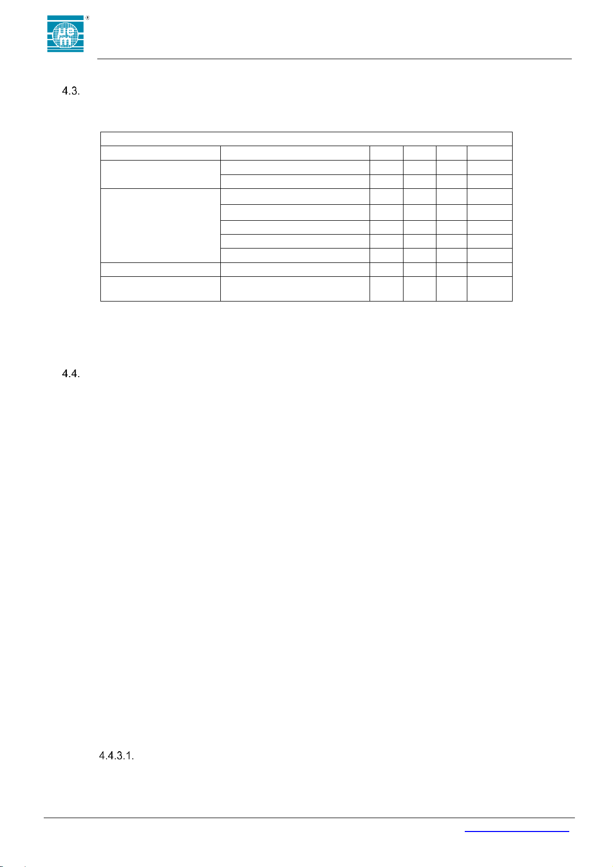
Table 4: Battery Life-Time and Range
Operating Mode
Specification
Min
Typ
Max
Unit
Warehouse Mode
Storage Time
1
years
Average Current
1.5 µA
Active Mode
(10% activity)
Daily Activity
10 %
Beacon Interval
1000 msec
Output Power
0
dBm
Average Current
3.8 µA
Line-of-Site(LOS) Distance
100 m
Sleep Mode
Daily Sleep Time
90 %
Battery Lifetime
CR2032 Battery
Above Use Case
5
years
ELECTRICAL CHARACTERISTICS
The electrical characteristics of are given in Table 4 for a typical use case.
Unless otherwise specified: VCC=3.0V, T=25°C
Note 1: Battery Lifetime is calculated based on the average current using a Renata CR2032 battery with 225mAh of
battery life under typical conditions.
Note 2: Beacon interval is the Bluetooth advertising interval (advInterval) as defined in the Bluetooth Specification
V5.0, Volume 6, Part B, and Section 4.4.2.2.
Note 3: Range is measured outdoors, line-of-site, with an iPhoneTM.
REGULATORY
EMBC22 is modular certified and complies with the following regulatory requirements:
4.4.1. USA-FCC
Single Modular Transmitter
EMC
FCC CFR 47, Part 15, Subpart B (10-1-17 Edition), Secs. 15.109
RF
FCC Part 15.247, 10-1-17 Edition: Operation within the bands 902 - 928 MHz, 2400 -2483.5 MHz,
and 5725 - 5850 MHz.
FCC Part 15.209, 10-1-17 Edition: Radiated emission limits; general requirements
4.4.2. Canada-IC
EMC
ICES-003 Issue 6 – Update April (2017)
RF
RSS-247 Issue 2 (February 2017).
RSS-Gen Issue 4 (November 2014).
4.4.3. CE
EM Microelectronic, as the responsible party for regulatory compliance, declares under our sole responsibility
that as delivered the described product is in conformity with the RED Radio Equipment Directive 2014/53/EU,
following the provisions of ERP Directive 2009/125/EC, EU RoHS Directive 2011/65/EU, including the
amendment 2015/863/EU on the restriction of the use of certain hazardous substances in electrical and
electronic equipment, and carries the CE-marking. Refer to emmicroelectronic.com for the signed declaration.
EMC
ETSI EN 301 489-1 V2.2.0
ETSI EN 301 489-17 V3.2.0
RF
ETSI EN 300 328 v2.1.1 (2016-11):
SAFETY File
1. Information on all plastics (flame rating and UL listing) model numbers
2. Battery: Specification, UL listing, and reports from vendor (Standards are UL 1642 and IEC/EN 62133)
3. PCB Board (same info as plastics)
4. Label (same info as plastics)
420005-A01, 2.0
Page 7
EMBC22 user manual
Copyright 2018, EM Microelectronic-Marin SA
EMBC22_user_manual_v3, Version 1.0 , 25-Sep-18
7
www.emmicroelectronic.com
Type
Max Gain
Integrated PCB IFA
1.5 dBi
5.4.4 REGULATORY INFORMATION USA
Changes or modifications not expressly approved by the party responsible for compliance could void the user’s
authority to operate the equipment.
This device complies with part 15 of the FCC Rules. Operation is subject to the following two conditions: (1)
This device may not cause harmful interference, and (2) this device must accept any interference received, including
interference that may cause undesired operation.
5.4.4.1 Class B device notice
NOTE: This equipment has been tested and found to comply with the limits for a Class B digital
device, pursuant to part 15 of the FCC Rules. These limits are designed to provide reasonable protection
against harmful interference in a residential installation. This equipment generates, uses and can radiate
radio frequency energy and, if not installed and used in accordance with the instructions, may cause
harmful interference to radio communications. However, there is no guarantee that interference will not
occur in a particular installation. If this equipment does cause harmful interference to radio or television
reception, which can be determined by turning the equipment off and on, the user is encouraged to try to
correct the interference by one or more of the following measures:
—Reorient or relocate the receiving antenna.
—Increase the separation between the equipment and receiver.
—Connect the equipment into an outlet on a circuit different from that to which the receiver is
connected.
—Consult the dealer or an experienced radio/TV technician for help.
5.4.4.2 RF exposure safety
This device meets the SAR Test Exclusion threshold specified in KDB447498 and is authorized for
portable and mobile operation. Installers and end-users must be provided with antenna installation
instructions and transmitter operating conditions and instructions for satisfying RF exposure compliance.
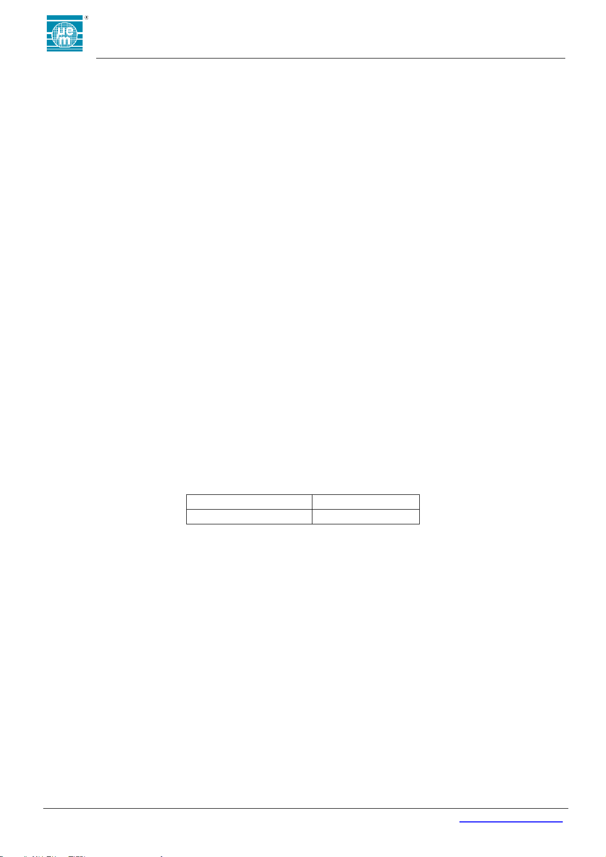
5.4.4.3 Permitted Antenna
This radio transmitter model, FCC ID: 2ACQR-EMBC22 has been approved by FCC to operate with the antenna
types listed below with the maximum permissible gain indicated. Antenna types not included in this list, having a gain
greater than the maximum gain indicated for that type, are strictly prohibited for use with this device.
5.4.4.4 Labelling Requirements for the Host Device
The host device shall be properly labelled to identify the modules within the host device.
The certification label of the module shall be clearly visible at all times when installed in the host
device, otherwise the host device must be labelled to display the IC of the module, preceded
by the words "Contains transmitter module", or the word "Contains", or similar wording
expressing the same meaning, as follows:
Contains FCC ID: 2ACQR-EMBC22
5.4.5 REGULATORY INFORMATION CANADA
Changes or modifications not expressly approved by the party responsible for compliance could void the user’s
authority to operate the equipment.
Les changements ou modifications non expressément approuvés par la partie responsable de la conformité
pourraient annuler l'autorisation de l'utilisateur d'utiliser l'équipement.
This device complies with Industry Canada’s license-exempt RSSs. Operation is subject to the following two
conditions: (1) This device may not cause interference; and (2) This device must accept any interference, including
interference that may cause undesired operation of the device.
420005-A01, 2.0
Page 8
EMBC22 user manual
Copyright 2018, EM Microelectronic-Marin SA
EMBC22_user_manual_v3, Version 1.0 , 25-Sep-18
8
www.emmicroelectronic.com
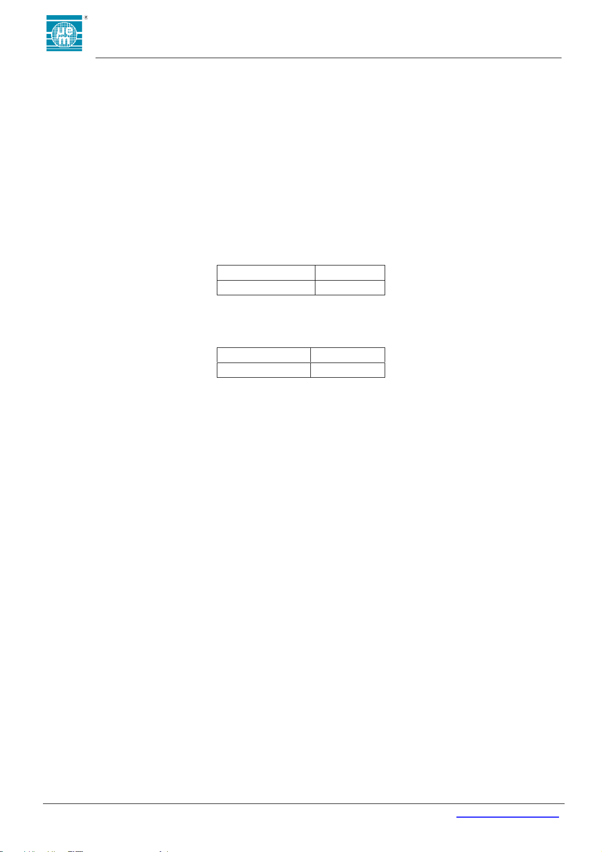
Type
Max Gain
Integrated PCB IFA
1.5 dBi
Type
Max Gain
Integrated PCB IFA
1.5 dBi
Le présent appareil est conforme aux CNR d'Industrie Canada applicables aux appareils radio exempts de licence.
L'exploitation est autorisée aux deux conditions suivantes : (1) l'appareil ne doit pas produire de brouillage, et (2)
l'utilisateur de l'appareil doit accepter tout brouillage radioélectrique subi, même si le brouillage est susceptible d'en
compromettre le fonctionnement.
5.4.5.1 RF Exposure Safety
According to “RSS-102 Issue 5 (2015-03) – Radio Frequency Exposure Compliance of
Radiocommunication Apparatus (All Frequency Bands)”, paragraph “2.5.1 Exemption Limits for
Routine Evaluation – SAR Evaluation”, the device operates below the applicable output power
level (adjusted for tune-up tolerance) for the specified separation distance. The evaluation has
been done at a distance of 5mm.
5.4.5.2 Permitted Antenna
This radio transmitter model, IC: 12155A-EMBC22 has been approved by the ISED to operate with the antenna
types listed below with the maximum permissible gain indicated. Antenna types not included in this list, having a gain
greater than the maximum gain indicated for that type, are strictly prohibited for use with this device.
Le présent émetteur radio modèle, IC: 12155A-EMBC22 a été approuvé par ISDE pour fonctionner avec les
types d'antenne énumérés ci-dessous et ayant un gain admissible maximal. Les types d'antenne non inclus dans cette
liste, et dont le gain est supérieur au gain maximal indiqué, sont strictement interdits pour l'exploitation de l'émetteur.
5.4.5.3 CAN ICES-3 (B)/NMB-3(B)
This Class B digital apparatus complies with Canadian ICES-003
Cet appareil numérique de clase B est conforme à la norme Canadienne ICES-003
5.4.5.4 Labelling Requirements for the Host Device
The host device shall be properly labelled to identify the modules within the host device. The
certification label of the module shall be clearly visible at all times when installed in the host
device, otherwise the host device must be labelled to display the IC of the module, preceded
by the words "Contains transmitter module", or the word "Contains", or similar wording
expressing the same meaning, as follows:
Contains IC: 12155A-EMBC22
L’équipement hôte doit être correctement étiqueté pour identifier les modules dans
l’équipement. L'étiquette de certification du module doit être clairement visible en tout temps
lorsqu'il est installé dans l'hôte, l’équipement hôte doit être étiqueté pour afficher l'IC du
module, précédé des mots "Contient le module émetteur", ou le mot "Contient", ou un libellé
similaire exprimant la même signification, comme suit:
Contains IC: 12155A-EMBC22
420005-A01, 2.0
Page 9
EMBC22 user manual
Copyright 2018, EM Microelectronic-Marin SA
EMBC22_user_manual_v3, Version 1.0 , 25-Sep-18
9
www.emmicroelectronic.com
Power On
Self Test
Warehouse
Mode
(Advertisements Off)
Configuration
Mode
(Connectable
Advertisements)
Beaconing Mode
(Adverti sements On)
Activity Mode
(Advertisements On
When Triggered)
Inactivity Mode
(Advertisements On
When Not Triggered)
Config
Event
Config
Timeout
(b)
On/Off Event
On/Off
Event
(b)
Config Event
(a)
Activity
Timeout
Activity
Event
(a) Event disabled after Lock Event occurs
(b) Event can be configured transition to “Beaconing”, rather than “Warehouse” Mode
POST
Pass (b)
Lock Event
Lock Event
Battery
Insert
Table 5: State Machine Configuration Options
Parameter
Options
Default
Hardware Features
Button
Red LED
Green LED
Accelerometer
All Enabled
Startup Mode
Warehouse Mode
Beaconing Mode
Warehouse Mode
Activity Event Source
Disabled
Short Button Press
Movement
Tap
Double Tap
Freefall
Flip
Movement
On/Off Event Source
Disabled
Short Button Press
Long Button Press
Flip
Short Button Press
Config Event Source
Disabled
Short Button Press
Long Button Press
Flip
Long Button Press
Config Timeout
0.1 to 6553.5 seconds
60 sec
Activity Timeout
0.1 to 6553.5 seconds
60 sec
6 FIRMWARE
The following is a basic description of EMBC22 firmware functionality.
6.4 STATE MACHINE
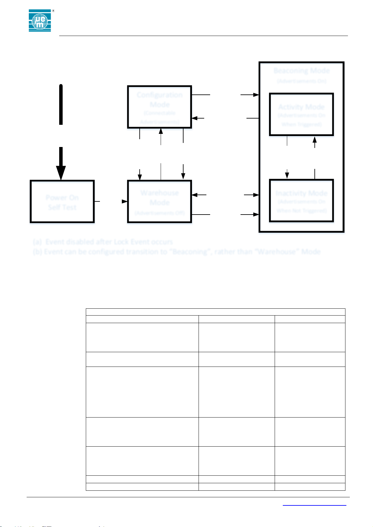
The state-diagram for the EMBC22 standard firmware is shown in Figure 3.
6.4.5 State Machine Configuration Options
Figure 3: Firmware State-Diagram
420005-A01, 2.0
Page 10
EMBC22 user manual
Copyright 2018, EM Microelectronic-Marin SA
EMBC22_user_manual_v3, Version 1.0 , 25-Sep-18
10
www.emmicroelectronic.com
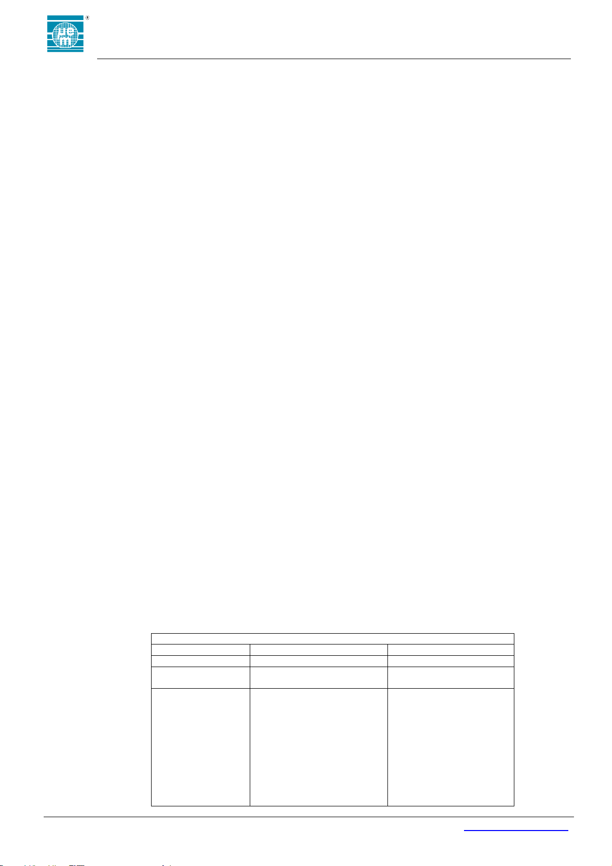
Table 6: Configuration Mode Advertisement Configuration Options
Description
Supported Type
Default
Packet Type
Connectable
Connectable
Advertisement
Interval
30ms - 18hrs
(1)
500 ms
TX Power Level
Settings (dBm)
6.2
4.6
2.5
0.4
-1.4
-2.6
-4
-5.5
-6.9
-8.4
-9.9
0.4 dBm
6.4.6 Hardware Features
The hardware features of the button, Red LED, Green LED and Accelerometer may be disabled in firmware.
The option to disable these hardware features is unavailable in the standard release of the EM9304 Beacon
Configuration Tool Suite. Options to control these features are made available on request in EM9304 Beacon
Configuration Tool Suite.
6.4.7 Operating Modes
Operating Modes of the EMBC22 are indicated with boxes in the Figure 3: Firmware State-Diagram. The
modes are fixed unless code patches are written and applied to redefine the states. Code patches may be
developed using the EM9304 Beacon SDK on the EMBC22 DVK. Behaviors within specific states, such as
advertisement profiles in the Beaconing Mode, can be redefined using the EM9304 Beacon Configuration
Tool Suite. No source code development is required when using the EM9304 Beacon Configuration Tool
Suite.
6.4.7.1 Power-On-Self-Test (POST)
On battery insertion, a self-test feature is run to confirm functionality of the key electrical components for
advertising. The test sequence follows the flow listed below:
1. Test the 32kHz crystal operation, red and green LEDs on
2. Test the 48MHz crystal operation, red LED on
3. Test the accelerometer, green LED on
4. LEDs off
If the test passes, both LEDs will turn off. If the test fails, one or more of the LEDs will remain on in the
present state to indicate which step failed.
6.4.7.2 Startup Mode
The startup mode is the mode that will be entered after POST or on a Config Timeout Event. The default
definition of Startup Mode and reassignment options are as defined in Table 5: State Machine
Configuration Options.
6.4.7.3 Warehouse Mode
In Warehouse Mode, the EMBC22 is in its lowest consumption state to support long term storage. A
Config Event, On/Off Event and Lock Event will all initiate exiting the Warehouse Mode. If a Config Event
or On/Off Events are defined to use the flip option, the accelerometer will be sampling at the rate defined
in the accelerometer configuration settings and the consumption will increase as defined in the Table 8:
Accelerometer Configuration Options at the selected sampling rate. If the Config Event and On/Off Event
are not defined to use the flip option, the accelerometer is in a power down state and the consumption of
the device is as defined in Section 4.3.
6.4.7.4 Configuration Mode
In Configuration Mode, the EMBC22 advertises a connectable advertisement at the default interval and
output power as defined in Table 6: Configuration Mode Advertisement Configuration Options. The
advertisement rate and output power may be redefined by the user. The configuration timer is started on
entry into the Configuration Mode. If no connections are made before the Config Timeout occurs, the
EMBC22 returns to the startup state. Exit from Configuration Mode is initiated by an On/Off Event, Lock
Event or Config Timeout. When a connection is made to the EMBC22, the part will stay in a connected
state until the master breaks the connection or is out of range. On disconnect, the EMBC22 initiates a
reset and returns to the POST state.
420005-A01, 2.0
Page 11
EMBC22 user manual
Copyright 2018, EM Microelectronic-Marin SA
EMBC22_user_manual_v3, Version 1.0 , 25-Sep-18
11
www.emmicroelectronic.com
-11.4
-13.1
-14.6
-16.4
-17.9
-29
-33.5
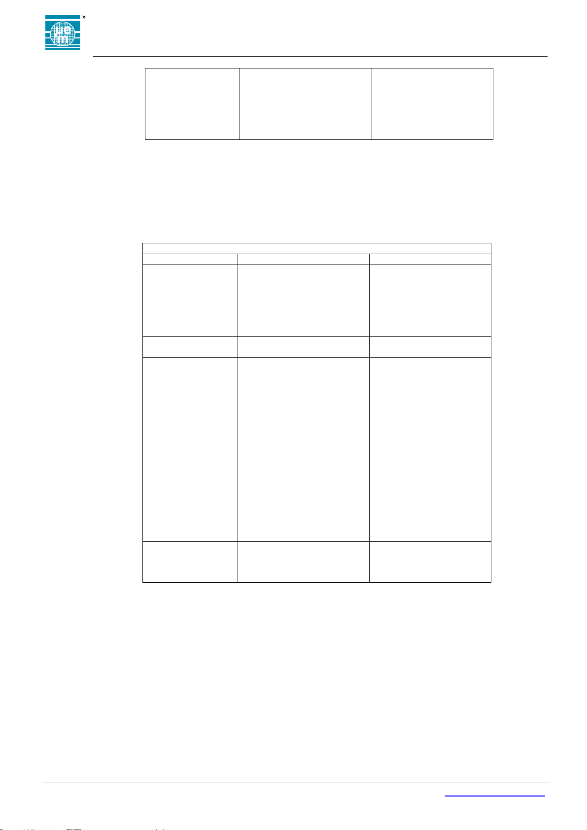
Table 7: Beaconing Mode Advertisement Configuration Options
Description
Supported Type
Default
Packet Type
iBeacon™
Eddystone UID™
Eddystone URL™
Eddystone TLM™
altBeacon™
Connectable
User Defined – Fixed Payload
Adv 1-10
Disabled
Advertisement
Interval
30ms - 18hrs
(1)
Adv 1-10
Disabled
Tx Power Level
Settings (dBm)
6.2
4.6
2.5
0.4
-1.4
-2.6
-4
-5.5
-6.9
-8.4
-9.9
-11.4
-13.1
-14.6
-16.4
-17.9
-29
-33.5
Adv 1-10
Disabled
Advertisement
Gating
Off
Always Enabled
Enabled when Active
Enabled when Inactive
Off
6.4.7.5 Beaconing Mode
In Beaconing Mode, the EMBC22 beaconing engine is enabled. The beaconing engine supports up to 10
advertisements running in parallel. Each advertisement may have a unique Packet Type, Advertisement
Interval, and Transmit Power Level. In addition, each advertisement may be gated such that the
advertisement is Always Enabled, Enabled Only When Active or Enabled Only When Inactive. Table 7:
Beaconing Mode Advertisement Configuration Options shows the configuration options available for each
advertisement.
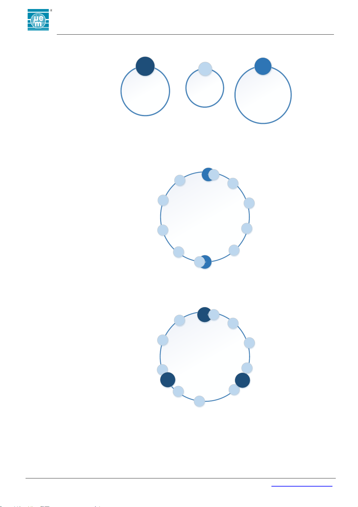
The beacon engine combines the settings of the 10 defined advertisement to create an interleaved
advertisement profile. Below is a diagram showing an example where three advertisements are enabled.
Adv1 is an Eddystone™ URL packet type with an output power of 0dBm at a 1 second interval and a
URL of www.Moving.com set to transmit when the module is moving. Adv2 is a Connectable
advertisement with an output power of -14dBm at a 300ms interval and is always enabled. Adv3 is an
420005-A01, 2.0
Page 12
EMBC22 user manual
Copyright 2018, EM Microelectronic-Marin SA
EMBC22_user_manual_v3, Version 1.0 , 25-Sep-18
12
www.emmicroelectronic.com
Adv 1
Enabled When Active
Type: ES URL
Power: 0dBm
www.Movi ng.com
ES
URL
Adv 2
Always Ena bled
Type: Connectable
Power: -14dBm
Conn
Adv 3
Enabled When Inative
Type: ES URL
Int: 375ms
Power:-5dBm
www.NotMoving.com
ES URL
1000ms
300ms
1500ms
Inactive
Advertisement
Interleaving
Example
ES-URL
Conn
ES-URL
3000ms
Conn
Conn
Conn
Conn
Conn
Conn
Conn
Conn
Conn
Active
Advertisement
Interleaving
Example
ES-URL Conn
3000ms
Conn
Conn
Conn
Conn
Conn
Conn
Conn
Conn
ES-URL
ES_URL
Conn
Eddystone™ URL packet type with an output power of -5dBm at a 1.5 second interval and a URL of
www.NotMoving.com set to transmit only when the module is not moving.
Figure 4: Example of three advertisements enabled
The beacon engine combines these three independent advertisement definitions to create appropriate
interleaved advertisement profiles based on the Activity Events detected. The part is in an Inactivity Mode
until an Activity Event is detected and the beacon engine manages interleaving the advertisement profiles
is as shown in the figure below.
Figure 5: Example advertisement interleaving in Inactivity Mode
Once an Activity Event is detected, the beacon engine reengages to disable the On When Inactive
advertisement and enable the On When Active advertisements. The resulting interleaved advertisement
for profile in this example is shown below.
When multiple advertisements are running in parallel timing collisions may occur. The firmware will make
priority decisions regarding which advertisement to send next. The advertising interval of one or more
packets is extended by a minimum of 30ms when collisions occurs in order to prevent violation to BLE
advertisement protocols.
Figure 6: Example advertisement interleaving in Activity Mode
420005-A01, 2.0
Page 13

EMBC22 user manual
Copyright 2018, EM Microelectronic-Marin SA
EMBC22_user_manual_v3, Version 1.0 , 25-Sep-18
13
www.emmicroelectronic.com
6.4.7.5.1 Activity Mode
6.4.7.5.2 Inactivity Mode
6.4.7.6 BLE Connection
6.4.8 Mode Transitions
Mode transitions of the EMBC22 are indicated with arrows in the Figure 3: Firmware State-Diagram. The start
and ending mode of transitions are fixed unless code patches are written and applied. Code patches may be
written using the EM Beacon SDK and developed on the EM Beacon DVK. The duration of a Config Timeout
or an Activity Timeout can be redefined using the EM Beacon Configuration Tools. Additionally, the source of
the Config Event and On/Off Event can be redefined using the EM Beacon Configuration Tools. No source
code development is required when using the EM Beacon Configuration Tools.
6.4.8.1 Config Event
6.4.8.2 Config Timeout
6.4.8.3 On/Off Event
6.4.8.4 Activity Event
Activity Mode is a subset of Beaconing Mode. When advertisements are assigned to this
Advertisement Gating option, the advertisement will only occur after an Activity Event has been
detected and for the duration of time defined by the Activity Timeout. Advertisements assigned
to the Always Enabled advertisement gating option will continue to be transmitted while in the
Activity Mode.
Inactivity Mode is a subset of Beaconing Mode. When advertisements are assigned to this
advertisement gating option, the advertisement will only occur when not in the Activity Mode.
Advertisements assigned to the Always Enabled advertisement gating option will continue to be
transmitted while in the Inactivity Mode.
A connection can be initiated from any mode where a connectable advertisement is sent. When a
connection is made, all accelerometer interrupt sources are disabled. If the connection was made from
Configuration or Activity Mode, the correlating timer continues to run while the connection is enabled. If
the corresponding timer expires while the connection is enabled, the timeout event will occur on
disconnect. Pressing the button during a connection will initiate a disconnect. If the corresponding timer
does not expire while the connection is still enabled, the mode that the connection was initially made in
will resume on disconnect. Specific services may initiate a Reset Event. A Reset Event will return the part
to POST.
A Config Event generates a transition from the Beaconing Mode or Warehouse Mode into Configuration
Mode. The Config Event may be assigned as defined in Table 6: Configuration Mode Advertisement
Configuration Options using the EM Beacon Configuration Tools. No source code development is
required when using the EM Beacon Configuration Tools.
The Green LED flashes twice when a Confg Event occurs.
On entry into the Configuration Mode, the configuration timer is started. A Config Timeout is generated
when that timer expires and initiates a transition from Config Mode to the startup mode. The duration of
the Config Timeout may be modified with the EM Beacon Configuration Tools as defined in Table 6:
Configuration Mode Advertisement Configuration Options. No source code development is required when
using the EM Beacon Configuration Tools.
The Red LED flashes twice when a Config Timeout occurs.
An On/Off Event generates a transition from the Beaconing Mode to Warehouse Mode, from
Configuration Mode to Beaconing Mode and from Beaconing Mode to Warehouse Mode. The On/Off
Event may be modified as defined in Table 6: Configuration Mode Advertisement Configuration Options
using the EM Beacon Configuration Tools. No source code development is required when using the EM
Beacon Configuration Tools.
When the On/Off Event initiates transitioning to Beaconing Mode, the Green LED is enabled while the
event is occurring. When the On/Off Event initiates transitioning to Warehouse Mode, the Red LED is
enabled while the event is occurring.
An Activity Event generates a transition from the Inactivity Mode to Activity Mode. The Activity Event may
be assigned as defined in Table 6: Configuration Mode Advertisement Configuration Options.
No LED indicators are used to communicate transitions between Activity and Inactivity Mode.
420005-A01, 2.0
Page 14
EMBC22 user manual
Copyright 2018, EM Microelectronic-Marin SA
EMBC22_user_manual_v3, Version 1.0 , 25-Sep-18
14
www.emmicroelectronic.com
Table 8: Accelerometer Configuration Options
Description
Available Options
Default
Units
Output Data Rate
Power Down
1.6
12.5
25
50
100
200
12.5
Hz
Power Mode
Low Power
High Performance
Low Power
-
Low Noise
Enable
Disable
Disabled
-
Filter Bandwidth
Div 2
Div 4
Div 10
Div 20
Div 2
-
Full Scale Range
2
4
8
16
2
G
Filter Selection
Low Pass
High Pass
Low Pass
-
Movement Threshold
0 to 63
4
-
Movement Duration
(Sequential Samples) 0 1
2
3
0
-
Flip 4D/6D
4D Detection
6D Detection
6D
-
6D Threshold
50
60
70
80
60
Degrees
6D Low Pass Filter
Enable
Disable
Disable
-
Tap Shock X Threshold
0 to 31
9
-
Tap Shock Y Threshold
0 to 31
9
-
Tap Shock Z Threshold
0 to 31
9
-
Tap Shock Time
4
16
Samples
6.4.8.5 Activity Timeout
6.4.8.6 Reset Event
6.4.8.7 Lock Event
6.4.9 Accelerometer Configuration
Configuration of key control registers on the accelerometer may be modified from the EM Beacon
Configuration Tools. The configurable options are listed in Error! Reference source not found.. Description
f the parameter are from the STM LIS2DWL datasheet DocID029682 Rev4. Additional details regarding the
impact on the operating behavior, consumption and performance of the device can be found in the
accelerometer datasheet.
On entry into the Activity Mode, the activity timer is started. An Activity Timeout is generated when the
activity timer expires and initiates a transition from Activity Mode to the startup mode. The duration of the
Activity Timeout may be modified with the EM Beacon Configuration Tools as defined in Table 6:
Configuration Mode Advertisement Configuration Options. No source code development is required when
using the EM Beacon Configuration Tools.
No LED indicators are used to communicate transitions between Activity and Inactivity Mode.
A Reset Event is initiated by battery insertion, toggling the enable signal from the test bus or from select
BLE services. A Reset Event clears data RAM and returns to the POST state to reinitialize the part.
After a Reset Event the LED indicators of POST running will be seen.
A Lock Event will disable the On/Off Event and initiate a transition to Beaconing Mode. The only way to
exit beaconing mode after an On/Off Event has been initiated is to issue a Reset Event.
The Green LED flashes three times when a Lock Event has been initiated.
420005-A01, 2.0
Page 15
EMBC22 user manual
Copyright 2018, EM Microelectronic-Marin SA
EMBC22_user_manual_v3, Version 1.0 , 25-Sep-18
15
www.emmicroelectronic.com
8
12
16
Tap Quiet Time
2
4
6
8
8
Samples
Double Tap Latency
16
32
48
64
80
96
112
128
144
160
176
192
208
224
240
256
128
Samples
Tap Axii
X Axis
Y Axis
Z Axis
All Enabled
-
Freefall Duration
0-63 Samples
3
-
Freefall Threshold
156
219
250
312
312
mg
6.5 ADVERTISEMENTS
The Bluetooth advertising packets are non-connectable, undirected advertising events (ADV_NONCONN_IND) which
follow the GAP specification according to the Bluetooth Specification V5.0, Volume 3, Part C, Section 11.
6.5.5 Device Address
Each EMBC22 has a unique factory-assigned address. The first 3 octets of the device address are the EM
Microelectronic OUI assigned address from the IEEE 802 committee: 0x0CF3EE. The last 3 octets of the
device address are uniquely assigned by EM Microelectronic. All advertisements enabled in the Beaconing
and Configuration Modes share the same Device Address.
The device address to be used may be modified with the EM Beacon Configuration Tools. If the address
00:00:00:00:00:00 is entered, then the factory-assigned address will be used.
6.5.6 Advertising Channels
Each EMBC22 has a unique factory-assigned address. The first 3 octets of the device address are the EM
Microelectronic OUI assigned address from the IEEE 802 committee: 0x0CF3EE. The last 3 octets of the
device address are uniquely assigned by EM Microelectronic. All advertisements enabled in the Beaconing
and Configuration Modes share the same Device Address.
420005-A01, 2.0
Page 16
EMBC22 user manual
Copyright 2018, EM Microelectronic-Marin SA
EMBC22_user_manual_v3, Version 1.0 , 25-Sep-18
16
www.emmicroelectronic.com
EM P/N:
Mfg date:
Module Lot Nr:
Qty:
EM P/N:
Mfg date:
Module Lot Nr:
Qty:
Weight:
7 LABEL
The label has the following contents:
Model: EMBC22
Unique Serial Number
FCC-ID: 2ACQR-EMBC22
IC ID: 12155A-EMBC22
7.4 SERIAL NUMBER
The serial number is generated by reading the device address of EMBC22, reversing the byte order, and printing the
number in decimal form.
For example:
Device Address: 0x0CF3EE5A0001 corresponds to Serial Number: 001101037237004
8 PACKING AND LABELING
8.4 FINISHED PRODUCT
8.4.5 Inner Packing
EMBC22 beacons are packed in custom antistatic trays.
Only one tray per box can have parts from 2 different product lots.
Tray size is 300 x 261 x 38 mm.
Number of parts per tray is 100pcs.
There are 5 trays per stack, excluding cover tray.
A label is applied on each stack. The minimum information on the label is specified in Figure 7.
FCC and CE Marking
EM Microelectronic company name
QR Code containing the unique Serial Number
8.4.6 External Packing
Tray stacks are packed in cardboard box.
Quantity of parts per box is 1000 pcs (2 tray stacks).
Box dimensions are 37 x 55 x 43 cm.
A label is applied on each box. The minimum information on the label is specified in Figure 8.
9 ACCESSORIES
Please reference the EMBC01 datasheet for description of available accessories.
10 ENVIRONMENTAL SAFETY
EMBC22 is:
RoHS compliant according to EU Directive 2011/65/EU and its amendments including 2015/863/EU
Halogen Free according to IEC 61249-2-21:2003.
REACH compliant according to EU Regulation 1907/2006
Figure 7: Packing label information
Figure 8: Panel packing label information
420005-A01, 2.0
Page 17
EMBC22 user manual
Copyright 2018, EM Microelectronic-Marin SA
EMBC22_user_manual_v3, Version 1.0 , 25-Sep-18
17
www.emmicroelectronic.com
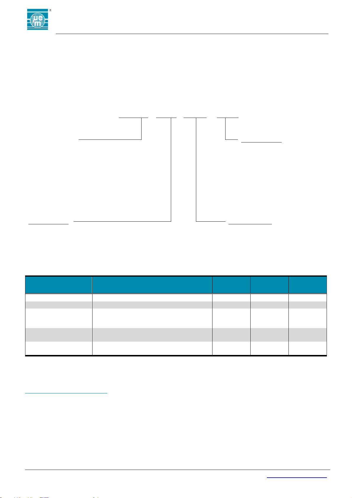
EMBC22
-
F001
H1000
Base Part Number
Housing Version:
EMBC22: Standard Version
EMBC22C: Version with connector
Hwxyz: housing, color, label, battery
w – housing option
x – cap option
y – label option
z – battery holder option
H0001: Beacon PCB, CR2032 holder
H1111: Standard beacon, CR2032
Other: Assigned by EM
Accessory Code:
Firmware Version:
DVK: Evaluation kit
Other: Assigned by EM
F403: Standard Version
Other: Assigned by EM
ORDER NUMBER
DESCRIPTION
CONTAINER
UNITS PER
CONTAINER
MINIMUM
ORDER
QUANTITY
EMBC22-F403-H1111
Standard Accelerometer beacon
Individual
1
1
EMBC22-F403-H1111
Standard Accelerometer beacon
Tray
100
100
EMBC22-F403-H0001
Accelerometer beacon PCB, CR2032 battery
holder, switch, (no battery). Special conditions
apply, please contact EM.
Tray
100
100
EMBC22C-F403-H0001
Accelerometer beacon PCB with connector,
CR2032 battery holder, switch, (no battery)
Individual
1
1
EMBC22DVK
EMBC22 Development Kit – includes 5 beacons
with connectors
Box 1 1
11 ORDERING INFORMATION
The EMBC22 is available as a finished product in a plastic housing with full FCC, IC, and CE certification. It is also available in
PCB form as a panel which requires country certification (ie FCC, CE, etc.) of final product performed by the customer. The
EMBC01 key-fob, wall-mount, and wrist-band accessories are available separately. Pre-certification beacons are available for
evaluation and development. The EMBC22 Beacon Development Kit is available with 5 pre-certification beacons, an interface
board, and JTAG cable for custom program development. The EMBC22 ordering information is shown in Figure 9 and the order
numbers are shown in Table 9.
12 CONTACT INFORMATION
Inquiries for lead-times, quotes, orders:
13 REFERENCE DOCUMENTS
EMBC01 device specification
EM9304 device specification
LIS2DWL device Specification
Bluetooth Specification V5.0
Proximity Beacon Specification Release R1 Draft D
Figure 9: EMBC22 Ordering Information
Table 9: EMBC22 Related Order Numbers
420005-A01, 2.0
Page 18
EMBC22 user manual
Copyright 2018, EM Microelectronic-Marin SA
EMBC22_user_manual_v3, Version 1.0 , 25-Sep-18
18
www.emmicroelectronic.com
EM Microelectronic-Marin SA (“EM”) makes no warranties for the use of EM products, other than those expressly contained in EM's applicable
General Terms of Sale, located at http://www.emmicroelectronic.com. EM assumes no responsibility for any errors which may have crept into
this document, reserves the right to change devices or specifications detailed herein at any time without notice, and does not make any
commitment to update the information contained herein.
No licenses to patents or other intellectual property rights of EM are granted in connection with the sale of EM products, neither expressly nor
implicitly.
In respect of the intended use of EM products by customer, customer is solely responsible for observing existing patents and other intellectual
property rights of third parties and for obtaining, as the case may be, the necessary licenses.
Important note: The use of EM products as components in medical devices and/or medical applications, including but not limited to,
safety and life supporting systems, where malfunction of such EM products might result in damage to and/or injury or death of
persons is expressly prohibited, as EM products are neither destined nor qualified for use as components in such medical devices
and/or medical applications. The prohibited use of EM products in such medical devices and/or medical applications is exclusively at
the risk of the customer.
Bluetooth is a trademark of the Bluetooth SIG. iPad and iPhone are trademarks of Apple Inc., registered in the U.S. and other countries. Android is a trademark of Google Inc. Google Play is a
trademark of Google Inc. Other product and company names mentioned herein may be trademarks of their respective companies.
420005-A01, 2.0
 Loading...