

R
EM MICROELECTRONIC - MARIN SA
EM4223
Read-only UHF Radio Frequency Identification Device
according to ISO IEC 18000-6
Description
The EM4223 chip is used in UHF passive read-only
transponder applications. The chip derives its operating
power from an RF beam transmitted by the reader, which
is received and rectified by the chip. It transmits its
factory-programmed code back to the reader by varying
the amount of energy that is reflected from the chip
antenna circuit (passive backscatter modulation).
The air interface communication protocol is implemented
according to ISO18000-6 type A.
The code structure supports the effort of EPCglobal, Inc.
as an industry accepted standard.
It additionally incorporates the Fast Counting
Supertag™ protocol for applications where the fast
counting of large tag populations is required.
The chip is frequency agile, and can be used in the
range of 800 MHz to 2.5GHz for RF propagating field
applications.
Typical Applications
Supply chain management (SCM)
Tracking and tracing
Asset control
Licensing
Auto-tolling
Key words
ISO 18000-6A
UHF
EPC™ data structure
Fast Supertag™
Features
Air interface is ISO18000-6 type A compliant
Supports EAN•UCC and EPC™ data structures as
defined by the Auto-ID center
Supports Fast Counting Supertag™ mode
128 bit user memory license plate Group select by
means of ‘Application Family Identifier’ (AFI)
according to ISO
Fast reading of user data during arbitration (no need
to first take an inventory)
Specific command set for supply chain logistics
support.
Frequency independent: Typically used at 862 - 870
MHz, 902 - 950 MHz and 2.45 GHz
Low voltage operation - down to 1.0 V
Low power consumption
Cost effective
-40 to +85°C operating temperature range
Benefits
Numbering scheme according to international
standards
Operates worldwide according to the local radio
regulation
Ideal for applications where long range and high-
speed item identification is required
Typical Operating Configuration
Connect pad A+
And V
dipole antenna
SS
to a
A+
EM4223
VSS
Chip design is a joint development with RFIP Solutions Ltd
VDD
Fig. 1
Copyright 2004, EM Microelectronic-Marin SA
1 www.emmicroelectronic.com

R
Table of contents
READ-ONLY UHF RADIO FREQUENCY
IDENTIFICATION DEVICE ACCORDING TO
ISO IEC 18000-6.................................................
Description ..................................................................1H1H1
Typical Applications ....................................................2H2H1
Key words ...................................................................3H3H1
Benefits.......................................................................4H4H1
TABLE OF CONTENTS.....................................5H5H2
Absolute Maximum Ratings ........................................6H6H3
Handling Procedures ..................................................7H7H3
Operating Conditions ..................................................8H8H3
Block Diagram.............................................................9H9H3
Electrical Characteristics.............................................10H10H4
Timing Characteristics ................................................11H11H4
1. GENERAL DESCRIPTION.................................12H12H5
2. FUNCTIONAL DESCRIPTION...........................13H13H5
General Command Format .........................................14H14H6
Supported Command set ............................................15H15H6
3. BASIC COMMAND FORMATS..........................16H16H6
Short commands.........................................................17H17H6
Extended commands ..................................................18H18H6
Implied MUTE command (Fast Supertag Mode only) .19H19H7
Command state transitions .......................................20H20H11
0H0H1
EM4223
COMMANDS AND STATES............................ 43H43H23
9.
Commands............................................................... 44H44H23
Tag States................................................................ 45H45H23
Tag state storage ..................................................... 46H46H24
10. COLLISION ARBITRATION............................ 47H47H25
General explanation of the collision arbitration
mechanism...............................................................
FST SYSTEMS ........................................................ 49H49H25
FST MODE OPTIONS.............................................. 50H50H26
Use of the round_size function (ISO & FST modes). 51H51H27
Ordering Information ................................................ 52H52H29
Versions ................................................................... 53H53H29
48H48H25
4. GENERAL REPLY FORMAT...........................21H21H14
5. FORWARD LINK ENCODING - READER TO
TRANSPONDER ..............................................
Carrier modulation pulses .........................................23H23H15
Basic time interval – definition of “Tari” .....................24H24H15
Data coding...............................................................25H25H16
Data Frame format....................................................26H26H16
Data decoding...........................................................27H27H17
Bits and byte ordering ...............................................28H28H17
Reader to Transponder 5 bit CRC (CRC-5) ..............29H29H17
Command Decoder...................................................30H30H17
22H22H15
6. RETURN LINK DATA ENCODING -
TRANSPORTER TO READER ........................
Return link data encoding .........................................32H32H18
Return link preamble.................................................33H33H19
Cyclic Redundancy Check (CRC) .............................34H34H19
31H31H18
7. MEMORY ORGANISATION AND
CONFIGURATION INFORMATION.................
Memory Map.............................................................36H36H19
Unambiguous User Data (UUD) & SUID...................37H37H19
AFI ............................................................................38H38H20
Personality Block ......................................................39H39H20
35H35H19
8. TRANSPONDER SELECTION OPERATION –
INIT_ROUND AND BEGIN_ROUND
COMMANDS.....................................................
INIT_ROUND COMMAND SELECTION OPERATION
..................................................................................
BEGIN_ROUND COMMAND SELECTION
OPERATION .............................................................
40H40H21
41H41H21
42H42H22
Copyright 2005, EM Microelectronic-Marin SA
2 www.emmicroelectronic.com
R
Absolute Maximum Ratings
Parameter Symbol Min Max
-0.3
-50
+3.6
+150
10
Table 1
Supply Voltage
V
– VSS (V)
DD
Storage temperature (°C)
RMS supply current pad A (mA)
V
DD
T
store
Stresses above these listed maximum ratings may cause
permanent damages to the device. Exposure beyond
specified operating conditions may affect device reliability or
cause malfunction.
Handling Procedures
This device has built-in protection against high static
voltages or electric fields; however, anti-static precautions
must be taken as for any other CMOS component. Unless
otherwise specified, proper operation can only occur when
all terminal voltages are kept within the voltage range.
Unused inputs must always be tied to a defined logic
voltage level.
Operating Conditions
Parameter Symbol Min Max Unit
Supply voltage VDD 1.0 3.5 V
Operating Temperature TA -40 +85 °C
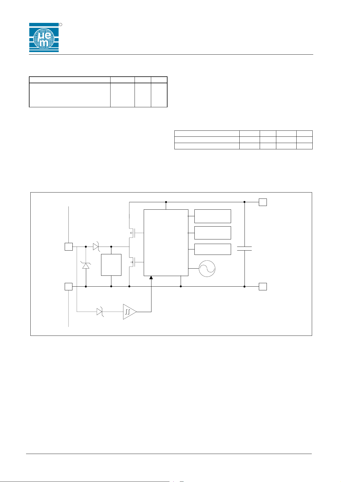
Block Diagram
Data
ROM 128b
EM4223
Table 2
V
DD
AFI
ROM 8b
Ant
V
SS
Limit
LOGIC
PON
OSC
CS
V
SS
Data
extractor
Fig. 2
Copyright 2005, EM Microelectronic-Marin SA
3 www.emmicroelectronic.com

R
EM4223
Electrical Characteristics
VDD= 2.0V, T
Operating voltage VDD – VSS V
Current consumption IS V
Power On Reset Rising V
Power On Reset Fall V
Electrostatic discharge HBM to MIL-STD-
Internal oscillator
frequency
Input series Impedance
@900MHz
Modulation depth
decoding
=+25°C, unless otherwise specified
A
Parameter Symbol Conditions Min. Typ. Max. Unit
3.5 V
ponf
= 1.5 V 2.0 3.9 uA
DD-VSS
1.2 V
ponr
1.0 V
ponf
883 method 3015
VDD and VSS pad
A+ pad
1.5
0.5
KV
Fosc Over full temperature range 192 320 448 KHz
Rin
C
in
– VSS < 1V 19
V
DD
0.620
At typical pulse width 27 % 100 % %
Timing Characteristics
Over full voltage and temperature range, unless otherwise specified
Parameter Symbol Conditions Min. Typ. Max. Unit
Forward Link
(Reader to Transponder)
Pulse width Tpw 100% modulation depth 6 10 14 uS
Pulse interval Data 0 T
Pulse interval Data 1 T
Return Link
(Transponder to Reader)
(note 1)
Bit rate accuracy
short term (note 2)
Bit rate accuracy
long term @1.5V
Reply to Receive
turn-around time
Receive to Reply
turn-around time
Tag Command window Tcw Opens at the start of the 3rd bit
Note 1: VDD= 2.0V, TA=+25°C
Note 2: V
= 2.0V
DD
average 33 kbps
100% modulation depth 12 20 28 uS
pi0
100% modulation depth 24 40 56 uS
pi1
nominal at 25°C as selected by
factory programmed Personality Bit
40
or
kbps
160
During a message transmission +/- 1 %
of nominal 40kb/s +/- 15 %
2 Bit
Depends on Transponders chosen
150 uS
reply slot
clock period after the end of the
last bit transmitted by the
Transponder to the reader. Closes
in the middle of the 5th bit clock
period.
KV
pF
Table 3
times
Table 4
Copyright 2005, EM Microelectronic-Marin SA
4 www.emmicroelectronic.com

R
1. GENERAL DESCRIPTION
The EM4223 is a monolithic integrated circuit transponder
for use in UHF passive backscatter RFID applications.
Operating power for the transponder circuit is derived
from the illuminating RF field of an RFID Reader by
means of an on-chip virtual battery rectifier circuit.
A user specified license plate or tag identifier is factory
programmed into the transponder by means of laser
trimming. This data is communicated to the reader by
means of backscatter modulation of the illuminating RF
carrier wave.
The EM4223 supports both the ISO18000-6 type A and
the Fast Supertag (FST) Protocols. The EM4223 may
be configured to wake-up in either of these modes
according to user requirements. Once active, the
transponder will automatically respond to either protocol
(and eventually switch modes) on receipt of the
appropriate commands.
2. FUNCTIONAL DESCRIPTION
When a Transponder is placed in the RF energising field
of a Reader it powers up. When the power supply has
reached the correct operating voltage, the Configuration
Register is loaded with the contents of the three preprogrammed personality flags. Depending on the state of
these wake-up flags, the Transponder will be placed in
either ISO 18000-6 Type A (ISO) or Fast Supertag (FST)
mode and in one of three states: READY, ACTIVE or
ROUND_STANDBY. After this process is complete the
Transponder is able to receive commands and to transmit
data to the Reader.
The Transponder is half-duplex and is thus in either
receive mode (default) or transmit mode. When not
actively transmitting messages to the Reader on the
Return Link, the Transponder will wait for the start of a
new command, which will be detected as a quiet period of
specific duration, followed by a valid Start Of Frame
(SOF) symbol (see
the quiet period in order to ensure that it does not detect
partial transmissions by a reader as a valid command.
This can occur if a transponder enters the field of a reader
and powers up part through a reader transmission. The
received SOF symbol is used to calibrate the command
decoder every time a command is received. This
calibration is used to establish a pivot to distinguish
between subsequent data ‘0’ and data ‘1’ symbols. Each
time that a new command is received by the Transponder,
the SOF re-calibrates the decode counter thereby
compensating for any variation in the Transponder clock
frequency due to changes in RF excitation levels or
temperature variations. The circuit has been designed to
accommodate a Transponder clock frequency variation of
+/-40% from nominal. When the Transponder is
transmitting the receive circuitry is disabled.
54H54HFig. 11). The Transponder requires
EM4223
All commands received from the Reader will have an
immediate effect on the Transponder. In addition, certain
commands will have a persistent effect. The possible
immediate effects are one or both of the following:
A change of State (see 55H55HFig. 19)
A Data Message sent to the Reader.
The possible persistent effects are:
Data Messages to the Reader will contain SUID (as
described later in this section) or Data Messages to
the Reader will contain USER DATA of 128 bits,
The Round Size (Number of Slots) over which all of
the Transponders in the population will spread their
Data Messages to the Reader will be configured.
The Transponder will switch between ISO and FST
modes of operation (as described below).
A sub-population of Transponders will be enabled to
send Data Messages to the Reader dependent on
either the AFI or on all or a portion of the USER
DATA of 128 bits.
The start of a command from the Reader has a special
significance if a Transponder is operating in the FST
mode and is in the ROUND_ACTIVE state. When the
falling edge of the first symbol of a command (SOF) is
received by a Transponder in the ROUND_ACTIVE state
while in FST mode, it will immediately move to the
ROUND_STANDBY state. If a command is successfully
received, the Transponder will move back to the
ROUND_ACTIVE state. If the Transponder does not
receive a valid command it will remain in the
ROUND_STANDBY state until a valid command has been
received. This enables the Reader to silence all
Transponders that have not already started sending their
Data Messages to the Reader in compliance with the FST
protocol. It is important to note that the Reader does not
have to send a full command or indeed even a part of a
command, as long as it sends a low going pulse of
approximately ½ Tari (Type A Reference Interval Time)
duration.
An important feature of this transponder is its ability to
switch seamlessly between ISO mode and FST mode
whatever its “wake up” personality setting, depending only
on the mode or characteristics of the controlling reader. A
Transponder that “wakes up” in the ISO mode on powerup will switch to the FST mode if it receives a
Wake_Up_FST command. Similarly, a Transponder that
“wakes up” in the FST mode on power-up will switch to
the ISO mode if it receives an INIT-ROUND, INITROUND-ALL or BEGIN-ROUND command.
Copyright 2005, EM Microelectronic-Marin SA
5 www.emmicroelectronic.com

R
Transponders will only transmit Data Messages to the
Reader while they are in the ROUND_ACTIVE state.
When the CURRENT SLOT NUMBER and the
SELECTED SLOT NUMBER values held by the
Transponder match, the Transponder transmits its Data
Message to the Reader. The Reply message will contain
either the SUID (the Integrated Circuit Manufacturer code
of 0x16 for MARIN and the lower 32 bits of the 128 bit
User Data) or the 128 bit User Data .
In situations where different groups of transponders
present in the reader field contain data having different
owners, a reader may selectively wake up these different
groups of transponders by means of the ISO compliant
AFI parameter in the Init_Round command or by using the
Mask parameter in the Begin_Round command. The
Begin_Round command additionally supports selection of
groups of transponders based on the user data content
according to the EPC™ method.
General Command Format
All commands are transmitted from the Reader to the
Transponder by means of pulse interval encoding as
defined in chapter 5: forward link encoding, beginning with
an SOF (Start Of Frame) and terminating in an EOF (End
Of Frame). Commands are supported in accordance with
the ISO 18000-6A specification which divides commands
into the categories of MANDATORY, OPTIONAL,
CUSTOM and PROPRIETARY. The EM4223 supports all
of the ISO 18000-6A MANDATORY commands and 4 of
the ISO 18000-6A OPTIONAL commands – Init_Round,
Close_Slot, New_Round and Begin_Round. In addition,
the EM4223 implements 1 PROPRIETARY command in
accordance with the ISO 18000-6A specification – this is
the Wake_Up_FST command which uses Op-Code 0x39.
Commands are divided into 2 basic types: Short
Commands of a fixed 16 bit length and Extended
commands which consist of a 16 bit section consistent
with the Short Command format followed by a variable
length extension containing various parameters and a
second CRC of 16 bit length which covers the entire
command, including the 1
been covered by the 5 bit CRC and the 5 bit CRC itself.
Supported Command set
The EM4223 fully supports the four ISO MANDATORY
commands: NEXT_SLOT, STANDBY_ROUND,
RESET_TO_READY and INIT_ROUND_ALL.
The ISO OPTIONAL commands: INIT_ROUND,
CLOSE_SLOT, and NEW_ROUND are also supported.
st
11 bits which will already have
EM4223
The BEGIN_ROUND command is included for Supply
Chain Logistics support.
In addition to the above, the Fast Supertag commands:
WAKE_UP_FST and MUTE are supported for compliance
with the FST protocol. MUTE is interpreted as any
partially decoded or invalid command as described in
section
3. BASIC COMMAND FORMATS
There are 7 short commands, 2 extended commands and
1 implied command.
Short commands
Short commands are a fixed length of 16 bits, which
includes a 5 bit CRC. The commands comprise the
following fields:
Protocol extension – 1 bit.
Command Op-code – 6 bits.
Parameters – 4 bits (parameters could include flags).
CRC – 5 Bits.
SOF RFU
Short commands are used for collision arbitration and
other immediate functions.
Extended commands
The EM4223 supports 2 Extended commands
(Init_Round and Begin_Round). They comprise a fixed
length part of 16 bits, which is identical with the format of
the 16 bit Short Commands described above, followed by
an 8 bit fixed length parameter in the case of both of the
Extended commands, followed by a 2
variable length up to 136 bits and terminated with a 16 bit
CRC. The Extended commands comprise the following
fields:
Protocol extension – 1 bit.
Command Op-code – 6 bits.
Parameters – 4 bits (parameters could include flags).
CRC – 5 Bits.
Extension of 8 bits (AFI) in the case of the
CRC-16 :- 16 Bits (over full message from after the
56H56H0.
(1 bit)
Command
Code (6 bits)
Fig. 3 General format, Short commands
Parameters &
Flags (4 bits)
CRC-5
(5 bits)
EOF
nd
parameter of
INIT_ROUND command, or an 8 bit
(MASK_LENGTH) parameter followed by a variable
length (MASK) parameter in the case of the
BEGIN_ROUND command
SOF to the last bit before the CRC16 itself).
Copyright 2005, EM Microelectronic-Marin SA
6 www.emmicroelectronic.com

R
EM4223
SOF
RFU
(1 bit)
Command
Code
(6 bits)
Parameters
& Flags
(4 bits)
CRC-5
(5 bits)
The 2 Extended commands supported by the EM4223
are used to all selected sub-populations of Tags to be
introduced to the Arbitration process.
Implied MUTE command (Fast Supertag Mode only)
When operating in the Fast Supertag Mode and in the
ACTIVE state, the reception of the first low-going pulse
of any command causes the EM4223 to move to the
ROUND_STANDBY state. This could be any single pulse
or the first pulse of the SOF of a valid command. The
Transponder will continue to decode the command. A
known and valid command causes the Transponder to
execute the command and to move to either the
ROUND_ACTIVE or the READY state, depending on the
command and its parameters (if any). An unknown
command or a command having an error will cause the
Transponder to remain in the ROUND_STANDBY state.
st
Optional
1
Parameter
(8 bits)
2nd Optional
Parameter
(0-136 bit)
Fig. 4 - General format, Extended commands
CRC-16
16 bits
EOF
During reception of a command, and until the command
has been correctly received, the Transponder will holdoff any attempt to reply until the command has been
correctly received and executed. At the end of receiving
a command, if it has not been correctly decoded, the
Transponder will remain in the ROUND_STANDBY state
until moved out of this state by the first correctly received
and decoded command.
If the Tag is in the Fast Supertag Mode and in the TTF
(Tag Talks First) sub-mode (Wake Up Status Flag =
X00), the Tag will automatically leave the
ROUND_STANDBY state after a timeout period of 2.5 X
176 tag bit periods has elapsed since the last MUTE
command (176 bits = maximum Tag Data Message
length).This timeout will be reset each time a new implied
MUTE command is received.
Command Protocol
Init-Round Always = 0 01 SUID
Next-Slot Always = 0 02 * Signature 4 bits 5 bits The signature must match the
Close Slot Always = 0 03 Ignored by
StandbyRound
New-Round Always = 0 05 SUID
Reset-ToReady
Init-RoundAll
Extension
Always = 0 04 * Ignored by
Always = 0 06 * Ignored by
Always = 0 0A * SUID
Op-
Code
bits
Parameter / flags
6
1 bit
EM4223
EM4223
1 bit
EM4223
1 bit
4 bits
Round
Size
3 bits
Round
size
3 bits
Round
size
3 bits
CRC-5 Extended
5 bits AFI
5 bits Advances the CURRENT
5 bits The signature is not used in
5 bits
5 bits Moves Transponder from
5 bits SUID = 0 tag responds with
parameters
16 bits SUID = 0 tag responds with
8 bits
CRC-16 Comments
the 128 bits of user data.
SUID = 1 tag responds with
SUID. If AFI field = 00H, all
tags respond, else if AFI is
other value, only tags with
matching AFI respond. Also
moves tags already active in
FST mode to ISO mode.
signature value transmitted by
the tag in its last reply to
acknowledge the tag’s reply.
Advances the CURRENT
SLOT COUNTER.
SLOT COUNTER.
this implementation because
the EM4223 has no select
state. The EM4223 will always
move to the
ROUND_STANDBY state.
current state to READY state.
the128 bits of user data. SUID
= 1 tag responds with SUID.
Also moves tags already
active in FST mode to ISO
mode.
Copyright 2005, EM Microelectronic-Marin SA
7 www.emmicroelectronic.com

R
BeginRound
Wake-UpFST
Mute Low
Always = 0 OB SUID
Always = 0 39 SUID
Pulse
EM4223
1 bit
1 Bit
Round
size
3 bits
Round
size
5 bits Mask
length
8 bits
5 bits
Wakes tag up in the Fast
Mask
value
0-136
bits
3 bits
Implied command in FST
16 bits Tags that match the MASK
value of MASK length will
move to the ROUND_ACTIVE
state from the
ROUND_STANDBY or
READY states or will remain
in the ROUND_ACTIVE state
if already there. Tags that do
not match the Mask will move
to the READY from either
ROUND_ACTIVE or
ROUND_STANDBY states.
SUID = 0 tag responds with
the 128 bits of user data.
SUID = 1 tag responds with
SUID, where the DSFID field
is replaced by AFI field. Also
moves Transponders already
active in FST mode to ISO
mode.
Supertag™ mode. Also
moves tags already active in
ISO mode to FST mode. SUID
= 0 tag responds with the 128
bits of user data SUID = 1 tag
responds with SUID.
mode. When tag receives an
SOF it moves to the
ROUND_STANDBY state.
The tag returns to the active
state on receipt of a next-slot
or init-round or new-round
command, or when a period of
2.5 X 176 tag bit periods has
elapsed since the last Mute
command (176 bits =
maximum message length).
Mandatory ISO commands op-codes are marked with an * and command titles are in bold type face.
Table 5- Supported Commands
Copyright 2005, EM Microelectronic-Marin SA
8 www.emmicroelectronic.com

R
Reader Command Transponder Operation in
ISO Mode
INIT_ROUND Initialises the start of the arbitration sequence
and tells the Transponder over how many slots
to randomise the transmit slot selection.
Configures the Transponder to transmit the
SUID data or the full 128 bit User Data to the
Reader dependent on the SUID parameter in
the command. Moves the Transponder from the
READY to the ROUND_ACTIVE states if the
Transponders AFI matches the AFI in the
command or if the AFI in the command = 0x00 .
If the AFI in the command is non-zero and does
not match the AFI in the Tag, causes the Tag to
move from the ROUND_ACTIVE to the READY
states.
BEGIN_ROUND Initialises the start of the arbitration sequence
and tells the Transponder over how many slots
to randomise the transmit slot selection.
Configures the transponder to transmit the
SUID data where DSFID field is replaced by
AFI field, or the full 128 bit User Data to the
reader, depending in the SUID parameter in the
command. Moves the Transponder from the
READY to the ROUND_ACTIVE states if the
number of bits of the Transponders User Data
specified in the command is identical to the
matching data in the command Mask
parameter .
INIT_ROUND_ALL Initialises the start of the arbitration sequence
and tells the Transponder over how many slots
to randomise the transmit slot selection.
Configures the Transponder to transmit the
SUID data or the full 128 bit User Data to the
Reader dependent on the SUID parameter in
the command. Moves the Transponder from the
READY to the ROUND_ACTIVE states.
NEW_ROUND Causes the EM4223 to enter a new Round and
to change the number of pseudo-slots over
which it randomises its transmissions. Tags in
the READY state will ignore this command.
WAKE_UP_FST Not supported in ISO Mode – causes the
Transponder to immediately switch to Fast
Supertag Mode.
EM4223
Transponder Operation in
Fast Supertag Mode
Not supported in Fast Supertag Mode –
causes the Transponder to immediately
switch to ISO Mode.
Not supported in Fast Supertag Mode –
causes the Transponder to immediately
switch to ISO Mode.
Not supported in Fast Supertag Mode –
causes the Transponder to immediately
switch to ISO Mode.
Causes the EM4223 to change the number of
pseudo-slots over which it randomises its
transmissions. Tags in the READY state will
ignore this command.
Initialises the start of the Fast Supertag
arbitration sequence and tells the
Transponder over how many slots to
randomise the transmit slot selection.
Configures the Transponder to transmit the
full 128 bit User Data to the Reader
irrespective of the SUID parameter in the
command. Moves the Tag from the
ROUND_STANDBY to the ROUND_ACTIVE
states or from the READY to the
ROUND_ACTIVE states if the Mask
parameter matches, else moves Tag to the
READY state.
Copyright 2005, EM Microelectronic-Marin SA
9 www.emmicroelectronic.com

R
NEXT_SLOT
CLOSE_SLOT
STANDBY_ROUND
RESET_TO_READY Moves the Transponder from its current state to
MUTE – this is not an actual
command but is an implied
command derived from the first
low-going pulse of any command.
Acknowledges the successful reception of a
Transponder transmission by the Reader when
valid ie. when received by a Transponder which
has just transmitted, and when the command is
received in the timing window and when the
Signature matches, causing the Transponder to
move from the ROUND_ACTIVE to the QUIET
states.
Causes a Transponder in the
ROUND_STANDBY state to move into the
ROUND_ACTIVE state.
Causes the Transponder Current Slot Counter
to increment by one.
Causes the Transponder to automatically start
a new Round by resetting its Current Slot
Counter and randomly selecting a new Reply
Slot when the Current Slot Counter has
reached the Round Size Value.
Causes a Transponder in the
ROUND_STANDBY state to move into the
ROUND_ACTIVE state.
Causes the Transponder slot counter to
increment by one.
Causes the Transponder to automatically start
a new Round by resetting its Current Slot
Counter and randomly selecting a new Reply
Slot when the Current Slot Counter has
reached the Round Size Value.
Causes the Transponder to move to the
ROUND_STANDBY state, in which the
Transponder does not transmit its identity or
data.
READY state.
Not used. The Transponder will move to the
EM4223
Acknowledges the successful reception of a
Transponder transmission by the Reader
when valid ie. when received by a
Transponder which has just transmitted, and
when the command is received in the timing
window and when the Signature matches,
causing the Transponder to move from the
ROUND_ACTIVE to the QUIET states.
Causes a Transponder in the
ROUND_STANDBY state to move into the
ROUND_ACTIVE state.
Causes a Transponder in the
ROUND_STANDBY state to move into the
ROUND_ACTIVE state.
Causes the Transponder to move to the
ROUND_STANDBY state, in which the
Transponder does not transmit its identity or
data. While in the ROUND_STANDBY state,
the random number generator for slot number
choosing is running so that transponder slots
are not synchronized and thus have maximum
spread and randomisation in the Transmit
times. When the Transponder exits the
ROUND_STANDBY state, it will wait until the
next internally generated slot time before reenabling its data transmit circuitry.
Moves the Transponder from its current state
to READY state.
ROUND_STANDBY state upon reception of
the first low-going pulse of any command.
This could be any single pulse or the first
pulse of the SOF of a valid command. The
Transponder will continue to decode the
command and if the pulse turns out to be part
of a valid command, the Transponder will
move to either the READY or the
ROUND_ACTIVE state depending on the
actual command and the command
parameters. If the WUS bit = 0 the
Transponder will automatically leave the
ROUND_STANDBY state after a timeout
period of 2.5 X 176 tag bit periods has
elapsed since the last MUTE command (176
bits = maximum Data Message length).This
timeout will be reset each time a new implied
MUTE command is received.
Table 6– Command Operations
Copyright 2005, EM Microelectronic-Marin SA
10 www.emmicroelectronic.com

R
EM4223
Command state transitions
The following tables show the state transitions for each of the commands supported by the EM4223 and should be read in
conjunction with
57H57HFig. 19.
Command : Init_Round (Tag will be in ISO mode after this command)
Initial State Criteria Action New State
AFI in the command = 0 or tags AFI value
matches the value in the command.
AFI in the command <> and Tags AFI value <>
Quiet None None Quiet
Round_Standby
AFI value in the command.
AFI in the command = 0 or tags AFI value
matches the value in the command.
AFI in the command <> and Tags AFI value <>
AFI value in the command.
AFI in the command = 0 or tags AFI value
matches the value in the command.
AFI in the command <> and Tags AFI value <>
AFI value in the command.
Tag chooses a random slot in which it
will send its response. Tag’s Current Slot
Counter is reset to first slot.
None Ready
Tag chooses a new random slot in which
it will send its response. Tag’s Current
Slot Counter is reset to first slot.
None Ready
Tag chooses a new random slot in which
it will send its response. Tag’s Current
Slot Counter is reset to first slot.
None Ready
Table 7 – Tag state transitions for Init_Round
Round_Active Ready
Round_Active Round_Active
Round_Active
Command : New_Round
Initial State Criteria Action New State
Ready None None Ready
Quiet None None Quiet
Round_Active None Tag chooses a new random slot in which
it will send its response. Tag’s Current
Slot Counter is reset to first slot.
Round_Standby None Tag chooses a new random slot in which
it will send its response. Tag’s Current
Slot Counter is reset to first slot.
Table 8 – Tag state transitions for New_Round
Round_Active
Round_Active
Command : Init_Round_All (Tag will be in ISO mode after this command)
Initial State Criteria Action New State
Ready None Tag chooses a random slot in which it
will send its response. Tag’s Current Slot
Counter is reset to first slot.
Quiet None None Quiet
Round_Active None Tag chooses a new random slot in which
it will send its response. Tag’s Current
Slot Counter is reset to first slot.
Round_Standby None Tag chooses a new random slot in which
it will send its response. Tag’s Current
Slot Counter is reset to first slot.
Table 9 – Tag state transitions for Init_Round_All
Round_Active
Round_Active
Round_Active
Copyright 2005, EM Microelectronic-Marin SA
11 www.emmicroelectronic.com

R
EM4223
Command : Begin_Round (Tag will be in ISO mode after this command)
Initial State Criteria Action New State
Ready
Number of bits of the MASK specified by
MASK_LENGTH in the command matches the
data in the Tag (AFI followed by USER DATA).
st
If the 1
8 bits of the MASK = 0 they are not
Tag chooses a random slot in which it
will send its response. Tag’s Current Slot
Counter is reset to first slot.
compared.
Number of bits of the MASK specified by
None Ready
MASK_LENGTH in the command does not
match the data in the Tag.
Quiet None None Quiet
Round_Active
Number of bits of the MASK specified by
MASK_LENGTH in the command matches the
data in the Tag (AFI followed by USER DATA).
st
If the 1
8 bits of the MASK = 0 they are not
Tag chooses a new random slot in which
it will send its response. Tag’s Current
Slot Counter is reset to first slot.
compared.
Number of bits of the MASK specified by
None Ready
MASK_LENGTH in the command does not
match the data in the Tag.
Round_Standby
Number of bits of the MASK specified by
MASK_LENGTH in the command matches the
data in the Tag (AFI followed by USER DATA).
st
If the 1
8 bits of the MASK = 0 they are not
Tag chooses a new random slot in which
it will send its response. Tag’s Current
Slot Counter is reset to first slot.
compared.
Number of bits of the MASK specified by
None Ready
MASK_LENGTH in the command does not
match the data in the Tag.
Table 10 – Tag state transitions for Begin_Round
Round_Active
Round_Active
Round_Active
Command : Wake_Up_FST (Tag will be in FST mode after this command)
Initial State Criteria Action New State
Ready None Tag chooses a random slot in which it
will send its response. Tag’s Current Slot
Counter is reset to first slot.
Quiet None None Quiet
Round_Active None Tag chooses a new random slot in which
it will send its response. Tag’s Current
Slot Counter is reset to first slot.
Round_Standby None Tag chooses a new random slot in which
it will send its response. Tag’s Current
Slot Counter is reset to first slot.
Table 11 – Tag state transitions for Wake_Up_FST
Round_Active
Round_Active
Round_Active
Copyright 2005, EM Microelectronic-Marin SA
12 www.emmicroelectronic.com

R
EM4223
Command : Next_Slot
Initial State Criteria Action New State
Ready None None Ready
Quiet None None Quiet
Round_Active
Tag has answered in previous slot, AND
Signature matches AND 1
st
low pulse of
Next_Slot command was received in the
acknowledgement time window.
Tag is in ISO Mode and has NOT
answered in previous slot, OR Signature
does not match OR 1
st
low pulse of
Next_Slot command was not received in
the acknowledgement time window.
Tag is in FST Mode and has NOT
answered in previous slot, OR Signature
does not match OR 1
st
low pulse of
Next_Slot command was not received in
the acknowledgement time window.
ISO Mode The tag shall increment its slot counter
FST Mode The tag resumes the FST Arbitration
None Quiet
The tag shall increment its slot counter
Round_Active
and send its response if slot counter
matches the chosen slot.
The tag will automatically increment is
Round_Active
Current Slot Counter at internally
determined times and send its response
if the its Current Slot Counter matches its
Selected Slot Register.
Round_active Round_Standby
and send its response if slot counter
matches the chosen slot.
Round_active
process and will automatically increment
is Current Slot Counter at internally
determined times and send its response
if the its Current Slot Counter matches its
Selected Slot Register.
Table 12 - Tag state transitions for Next_Slot
Command : Close_slot
Initial State Criteria Action New State
Ready None None Ready
Quiet None None Quiet
Round_Active
ISO Mode The tag shall increment its slot counter
Round_Active
and send its response if slot counter
matches the chosen slot.
FST Mode The tag will automatically increment is
Round_Active
Current Slot Counter at internally
determined times and send its response
if the its Current Slot Counter matches its
Selected Slot Register.
ISO Mode The tag shall increment its slot counter
Round_active Round_Standby
and send its response if slot counter
matches the chosen slot.
FST Mode The tag resumes the FST Arbitration
Round_active
process and will automatically increment
is Current Slot Counter at internally
determined times and send its response
if the its Current Slot Counter matches its
Selected Slot Register.
Table 13 - Tag state transitions for Close_Slot
Command : Reset_To_Ready
Initial State Criteria Action New State
Ready None None Ready
Quiet None None Ready
Round_Active None None Ready
Round_Standby None None Ready
Table 14 - Tag state transitions for Reset_To_Ready
Copyright 2005, EM Microelectronic-Marin SA
13 www.emmicroelectronic.com

R
EM4223
Command : Standby_Round
Initial State Criteria Action New State
Ready None None Ready
Quiet None None Quiet
Round_Active None None Round_Standby
Round_Standby None None Round_Standby
Table 15 – Tag state transitions for Standby_Round
4. GENERAL REPLY FORMAT
The Transponder will reply to a successful arbitration sequence by sending a message having the following format:
Preamble – see description of the Return Link.
Flags – 2 bits (Preset)
Parameters as follows:
Transponder type – 1 bit (Always = 0)
Battery status – 1 bit (Always = 0)
Signature – 4 bits (last 4 bits of the clock counter).
Data – 136 bits if the SUID bit = 0 as follows:
AFI of 8 bits.
User Data of 128 bits.
Data – 48 bits if the SUID bit = 1 as follows:
DSFID of 8 bits.
SUID of 40 bits (lower 32 bits of User Data + IC Manufacturer code).
CRC – 16 bits
Preamble Flags Parameters Data CRC
Fig. 5- Transponder Reply, general format
Preamble Flags Trans. Type Battery
Status
2 bits Always = 0 Always = 0 4 bits 8 bits 128 bits 16 bits
The above reply will be received after a successful arbitration sequence that was initiated by the Init-Round, Init-RoundAll, Begin_Round and Wake-Up_FST commands with the SUID flag = 0.
Signature AFI USER DATA CRC16
Fig. 6 – Transponder Reply to commands with the SUID flag = 0.
Preamble Flags Trans. Type Battery Status Signature DSFID SUID CRC 16
2 bits Always = 0 Always = 0 4 bits Always = 0x00 40 bits 16 bits
Fig. 7 – Transponder Reply commands with the SUID flag = 1.
The above reply will be received after a successful arbitration sequence that was initiated by the Init_Round,
Init_Round_All and Wake_Up_FST commands with the SUID flag = 1.
Preamble Flags Trans. Type Battery Status Signature AFI SUID CRC 16
2 bits Always = 0 Always = 0 4 bits 8 bits 40 bits 16 bits
Fig. 8 – Transponder Reply to Begin_Round command with the SUID flag = 1.
The above reply will be received after a successful arbitration sequence that was initiated by the Begin_Round command
with the SUID flag = 1.
Copyright 2005, EM Microelectronic-Marin SA
14 www.emmicroelectronic.com

R
5. FORWARD LINK ENCODING - READER TO TRANSPONDER
Commands and data are received from the Reader,
encoded by means of Pulse Interval Encoding. The
Reader transmits pulses in the form of dips in its carrier
wave. The intervals between dips convey information in
accordance with the following description.
The Transponder responds to transmissions by the
Reader as described herein.
Carrier modulation pulses
The data transmission from the Reader to the
Transponder is achieved by modulating the carrier
amplitude (ASK). The data coding is performed by
generating pulses at variable time intervals. The duration
of the interval between two successive pulses carries the
data coding information. This is known as Pulse Interval
Encoding, (PIE). The Transponder measures the interpulse time on the high to low transitions (falling) edges of
the pulse as shown in 58H58HFig. 9
Basic time interval – definition of “Tari”
The time “Tari” specifies the period in microseconds
between two falling edges representing the symbol “0”.
The word “Tari” is an acronym for “Type A Reference
Interval Time” as defined in the ISO18000-6 Type A
specification. The period between the two falling edges
defining each of the other symbols is based on a multiple
of the basic Tari period. The SOF symbol (Start of
Frame) consists of 2 periods, the 1
st
of which is equal to
EM4223
One Tari, while the 2nd period of the SOF symbol is equal
to 3 Tari. The first part of the SOF symbol is provided to
allow detector circuitry to settle (should this be
necessary). The second part of the SOF symbol is used
as a Calibration period. The received SOF symbol is
used to calibrate the command decoder every time a
command is received. This calibration is used to
establish a pivot to distinguish between subsequent data
‘0’ and data ‘1’ symbols. The pivot point has a value of
1.5Tari and is derived from the 3Tari interval contained in
nd
part of the SOF symbol. The binary data ‘0’ and
the 2
‘1’ are extracted from the incoming data stream by
comparing the inter-pulse interval with a pivot point. If the
interval is less than the pivot, then the binary value is ‘0’
and if it is greater than the pivot then the binary value is
‘1’ (See clause
received by the Transponder, the SOF re-calibrates the
decode counter thereby compensating for any variation
in the Transponder clock frequency due to changes in
RF excitation levels or temperature variations. The circuit
has been designed to accommodate a Transponder
clock frequency variation of ±40% from nominal. The
basic Tari period as transmitted by the Reader is
specified in
Tari
59H59H0). Each time that a new command is
60H60HTable 16 and illustrated in 61H61HFig. 9.
Tari Tolerance
20 µs ±100 ppm
Table 16 - Reference interval timing
100%
M
Fig. 9 - Inter-pulse mechanism
Copyright 2005, EM Microelectronic-Marin SA
15 www.emmicroelectronic.com

R
Data coding
Data transmitted by the Reader to the Tag is encoded in
PIE format as described in
62H62H0 and 63H63H0 above. Four symbols
are encoded; ‘0’, ‘1’, SOF and EOF. The Transponder is
able to decode symbols having values as shown in
64H64HFig.
10 below.
Symbol Mean
duration
0 1 Tari ½ Tari < ‘0’ ≤ 3/2 Tari
1 2 Tari 3/2 Tari < ’1’ < 3 Tari
SOF
1 Tari followed
by 3 Tari
EOF 4 Tari ≥ 4 Tari
Table 17 - PIE symbols
Limits
Calibration sequence
EM4223
Values falling outside of the limits in
17 will cause the received data to be rejected and
Table
the EM4223 to wait for an unmodulated carrier of EOF
duration or greater before being ready to receive a new
command.
Time interval in "Tari"
Symbol
'0'
'1'
'EOF'
'SOF'
Fig. 10 - PIE symbols
1234
65H65H
Data Frame format
The bits transmitted by the Reader to the Transponder
are embedded in a frame as specified in
66H66HFig. 11. Before
sending the frame, the Reader ensures that it has
established an unmodulated carrier for duration of at
least Taq (Quiet time) of 300µs.
Taq
1Tari
3 Tari
BBB B
Quiet
SOF
The frame consists of a Start-Of-Frame (SOF),
immediately followed by the data bits and terminated by
an End-Of-Frame (EOF). After sending the EOF the
Reader maintains a steady carrier for sufficient time to
allow all Transponders present to be powered so that
they may send their Reply.
Command + Data
EOF
Fig. 11 - Forward link frame format
Copyright 2005, EM Microelectronic-Marin SA
16 www.emmicroelectronic.com

t
R
Data decoding
The binary data ‘0’ and ‘1’ are extracted from the
incoming data stream by comparing the inter-pulse
interval with a pivot point. The pivot point has a value of
1.5Tari and is derived from the 3Tari interval contained in
the 2nd part of the SOF symbol. If the interval is less than
the pivot, then the binary value is ‘0’ and if it is greater
than the pivot then the binary value is ‘1’.
1100
1100
EM4223
If the Transponder detects an invalid code it discards the
frame and waits for an unmodulated carrier of EOF
duration. No Error Messages are sent to the Reader.
Bits and byte ordering
Coding of data into symbols is MSB first. The coding for
the 8 bits of hex byte 'B1' is shown in
67H67HFig. 12.
Ts0
Reader to Transponder 5 bit CRC (CRC-5)
The CRC-5 is used only for commands from the Reader
to the Transponder. All commands have a CRC-5 as the
last 5 bits of the first 16 bit part of an Extended command
or as the last 5 bits of a Short Command. The CRC-5 is
calculated on all the command bits after the SOF up to
the end of the Extended Parameters (11 bits in total –
see
68H68HFig. 3).
The polynomial used to calculate the CRC-5 is x^5 + x^3
+1. The CRC-5 register is pre-loaded with '01001' (MSB
(C4) to LSB (C0)) prior to commencing a CRC-5
calculation in both the case of a Reader to Transponder
command transmission and the case of a Transponder
initializing its CRC-5 register prior to receiving a
command from the Reader.
The 5 bits of the CRC-5 embedded in the command are
received MSB first by the Transponder. The Transponder
will clock the first 16 bits of an Extended command or a
complete Short Command through its CRC-5 register as
it is receiving the command from the Reader and if these
16 bits were received without error, the Transponder’s
CRC-5 register will contain all zeros after the last bit has
been clocked through.
Command Decoder
The Transponder can receive commands from a Reader
at any time other than the time that it is transmitting a
Fig. 12 - Example of PIE byte encoding for 'B1'
Reply to the Reader and during the 2 Transponder bit
periods following a Reply transmission.
In the case of the Next_Slot command the command is
interpreted by the Transponder in one of two ways.
If a Next_Slot command is received such that the
first pulse of the command is received during the
active command window of the Transponder, which
follows a transmission by the Transponder and this
Next_Slot command contains a signature parameter
that matches that sent by the Transponder in its last
transmission, then the command will be interpreted
as an instruction for that Transponder to move to the
quiet state
69H69HFig. 13 and below show the timing of the
Transponder command window.
If a Next_Slot command is received at any time
other than coincident with an active command
window (opened by the Transponder following a
transmission) or if the Transponder had not
transmitted a Reply immediately prior to receiving
the NEXT_SLOT command or if the Next_Slot
command does not contain a signature parameter
that matches that sent by the Transponder in its last
transmission then the command is interpreted as an
instruction to step the current slot counter value in
ISO mode or as a command to exit the
ROUND_STANDBY state in either ISO or FST
modes.
Copyright 2005, EM Microelectronic-Marin SA
17 www.emmicroelectronic.com

A
R
EM4223
Tag bits after last transmitted bit
carrier
modulated
state level
Tag not
reflecting
Tag
transmission
Tag listens
Interrogator
RF field
End of last
carrier steady
state level
tag bit
123456
the last tag data transition occurs
at either the centre or end of the
last bit period depending on FM0
state.
Tag Command Window
1st high to low transition of the
command shall occur in this time.
Fig. 13 - Command Window Timing
6. RETURN LINK DATA ENCODING - TRANSPORTER TO READER
The return link data is modulated onto the impinging illuminating RF carrier using varying impedance modulation.
Return link data encoding
Data is encoded using Bi-phase space (FM0).
FM0 Data Coding
MSB first encoding of Byte 10110001 = 'B1'
lternative
depending on
prior conditions
1
1
1
00
100
t
Trlb
Fig. 14 - Return link – data encoding
Copyright 2005, EM Microelectronic-Marin SA
18 www.emmicroelectronic.com

R
Return link preamble
The FM0 return link preamble has the bit pattern described in Error! Reference source not found.
Tag bit periods
23 45 6 7 8
1
Preamble waveform
'
1' is tag reflecting, '0' is tag not reflecting
910
11 12
13
14
16
15
Fig. 15 - FM0 Return link preamble
Cyclic Redundancy Check (CRC)
The 16 bit CRC is calculated on all data bits up to, but
not including, the first CRC bit.
The polynomial used to calculate the CRC is x^16 + x^12
+ x^5 + 1.
MSByte LSByte
MSB LSB MSB LSB
CRC 16 (8 bits) CRC 16 (8 bits)
first transmitted bit of the CRC
The 16-bit register is preloaded with 'FFFF’. The resulting
CRC value is inverted, attached to the end of the packet
and transmitted.
The most significant byte shall be transmitted first. The
most significant bit of each byte shall be transmitted first.
EM4223
7. MEMORY ORGANISATION AND CONFIGURATION INFORMATION
Memory Map
The physical memory comprises 128 bits of user
memory, 8 bits AFI and 3 personality bits. In addition, the
IC Manufacturer Code as specified in ISO7816-6/AM1 is
hard-wired into the Transponder.
128 bits UUD memory 8 bit AFI 3 bits Personality
Fig. 17- Memory map
Unambiguous User Data (UUD) & SUID
The user memory on the Transponder comprises 128
bits of user specified data. This data is known as
Unambiguous User Data UUD, because it is expected
that this data be unique and unambiguous. The UUD is a
license plate defined by the user and may be an EPC™,
GTAG™ or other user defined number.
The Transponder will return a Sub-UID (SUID) as defined
in ISO 18000-6 when the SUID flag is =1 in the
arbitration initiation commands. The SUID in this
Transponder is derived from the least significant 32 bits
of the UUD as described below. The SUID consists of 40
bits: the 8 bit manufacturer code followed by the least
significant 32 bits of the UUD.
Fig. 16- CRC format
Copyright 2005, EM Microelectronic-Marin SA
19 www.emmicroelectronic.com

R
MSB
Upper bits of UUD
MSB LSB
40 33 32 1
IC Mfg code “0x16”
Hard wired in EM4223.
Transponder Unique Identifier (UID) & SUID
An ISO 18000-6A Transponder does not transmit the UID
except in response to the optional
Get_System_Information command which is not
supported in the EM4223. All other transactions are
conducted using the SUID (which is supported).
The Interrogator derives the Transponder 64 bit UID from
the SUID and it is made up as follows:
Bits 57 Æ 64 are always set to Hex ‘E0’.
Bits 49 Æ 56 carry the Integrated Circuit
Manufacturers Code
Bits 33 Æ 48 are always set to Hex ‘0000’
Bits 1 Æ 32 carry the 32 bit Serial number.
AFI
Application Family Identifier - 8 bits per ISO 18000-6
clause 7.2.3. If the AFI byte is set with all 00 the tag will
respond, or if the AFI in the tag matches the AFI byte in
the init-round command the tag will respond, otherwise
the tag will remain quiet.
Wake Up
FST/ISO Flag
(pbit 1)
1 1 READY – Transponder replies in its selected
1 0 READY - Transponder replies in both the first
0 1 ROUND_STANDBY state, Reader Talks First
0 0 ROUND_ACTIVE –Tag Talks First mode SUID flag = 0
Personality Block 0- Bit 2 determines the Transponder Reply data rate:
0 = 40 kb/s
1 = 160 kb/s
Status
Flag
(pbit 0)
128 40 33 32 1
Serial number (Lower 32
Serial number
Personality Block
The personality block contains 3 control bits. The default
ISO
state of these bits is programmed during manufacture.
These bits control the Wake Up Status flag (WUS), the
power up selection of FST or ISO mode of operation and
the Return Link Bit Rate.
Transponders will power up in the default mode set by the
bits programmed during manufacture. Only the FST/ISO
mode flag can be changed by Reader commands.
Transponders will be switched to FST mode by the
WAKE_UP_FST command. INIT_ROUND,
INIT_ROUND_ALL and BEGIN_ROUND commands will
switch Transponders to the ISO mode of operation.
The state of the WUS bit cannot be changed from the
value set during manufacture. Transponders will operate
in ISO or MOD_ISO mode depending on the factory
programmed state of the WUS bit. Similarly,
Transponders will operate as TTF or as RTF in FST
mode depending on the factory programmed state of the
WUS bit. It is important to note that tags can only switch
between MOD_ISO and FST (TTF) or between ISO and
FST (RTF) modes.
Transponder SUID and
Tag State
Roundsize Initialize
Power Up Condition
slot in each round.
slot and its selected slot in every round
mode
Table18 - Transponder Operational Modes
EM4223
LSB
bits of UUD)
Fig. 18- UUD/SUID mapping
Mode
Conditions
Don’t care ISO
Don’t care MOD_ISO
SUID flag = 0
Roundsize = 16
Roundsize = 16
FST (RTF)
FST (TTF)
Copyright 2005, EM Microelectronic-Marin SA
20 www.emmicroelectronic.com

R
8. TRANSPONDER SELECTION OPERATION – INIT_ROUND AND BEGIN_ROUND COMMANDS
The INIT_ROUND and BEGIN_ROUND commands have
the ability to move only a selected sub-set of the
Transponder population from the READY to the
ROUND_ACTIVE states. Transponders that are already
in the ROUND_ACTIVE or ROUND_STANDBY states
will be removed from the active Transponder population
and moved to the READY state if they do not match the
selection parameters sent with the INIT_ROUND or
BEGIN_ROUND command.
This allows the population to be “thinned”, thus
increasing the effective read rate achieved.
EXPLANATION OF “DETERMINISTIC” OPERATION BASED ON “TREE-WALKING”
Transponders that use randomly selected reply slots in order to transmit their data to a Reader have a
very small risk of more than one Transponder selecting the same slot several times, which could mean
that such tags may not be read before they move out of the active population. This is known as
“Probabalistic” operation and must be balanced against the many advantages of this mode of operation.
“Tree Walking” is a method of resolving Transponder populations by effectively issuing a series of “tests”
or “challenges” in which the Reader would request a response from all tags containing say “0” in the 1
position of the Transponder data (or in an encrypted version of the data). If the Reader received a nonclashing response (only 1 transponder responding) it could request that Transponder to send its full data.
If the Reader received a clashing response (more than 1 transponder responding) it would know that it
had identified a productive “branch” and would extend its test by requesting a response from all tags
containing say “00” in the 1
st
two bit positions of the Transponder data. It would continue testing and
requesting responses until it had resolved the entire tag population in this manner. If the Reader received
no response it would know that it had identified an unproductive “branch” and would temporarily abandon
further testing for Transponders with “0” in the 1
st
Transponders with “1” in the first bit position. This would continue until all Transponders had been
identified, or moved out of the Reader’s RF field.
INIT_ROUND COMMAND SELECTION OPERATION
70H70HFig. 19)
(see
The INIT_ROUND command contains a single fixed
length (8 bit) selection parameter. This parameter
represents the AFI (Application Family Identifier
according to ISO18000-6A) value which will be matched
with the AFI value contained in the Transponders
memory. Transponders with a matching AFI value will
move from the ROUND_ACTIVE or ROUND_STANDBY
or READY states to the ROUND_ACTIVE state and
commence participation in the Arbitration process.
Transponders that do not match the AFI value sent in the
command will remain in the READY state or they will
move to the READY state if they are already in the
ROUND_ACTIVE or ROUND_STANDBY states.
EM4223
Because only transponders of interest to the application
will be selected any other Transponders in the Reader
field will not degrade Reader performance by needing to
be read and acknowledge to send them to the QUIET
state – they virtually do not exist if they have not been
selected.
The selection capabilities also allow the Transponder
population to be “Tree-Walked” allowing fully
“Deterministic” arbitration of a Transponder population.
By adding more and more bits to the selection criteria,
the population can be resolved down to a single
Transponder. (See the explanatory note below).
st
bit
bit position. The Reader would then test for
If the AFI value contained in the INIT_ROUND command
is 0x00, the Transponders will ignore the parameter in
the command and all Transponders will move to the
ROUND_ACTIVE state from the ROUND_ACTIVE or
ROUND_STANDBY or READY states. With an AFI
parameter of 0x00, the command will perform identically
to an INIT_ROUND_ALL command.
Tags in the QUIET state will ignore the INIT_ROUND
command.
Copyright 2005, EM Microelectronic-Marin SA
21 www.emmicroelectronic.com

R
BEGIN_ROUND COMMAND SELECTION OPERATION
71H71HFig. 19)
(see
The BEGIN_ROUND command contains 2 selection
parameters. The 1
st
parameter, called MASK_LENGTH,
consists of a fixed length (8 bit) value, which specifies
how many bits will be sent in the following parameter,
called the MASK. This MASK_LENGTH will be between
0 and 136 for the EM4223. The MASK value will be
compared to the number of bits of the tags data memory
specified in the MASK LENGTH parameter.
Transponders with data matching the MASK in the
command will move from the ROUND_ACTIVE or
ROUND_STANDBY or READY states to the
ROUND_ACTIVE state and commence participation in
the Arbitration process. Transponders whose data does
not match the MASK
value sent in the command will
remain in the READY state or they will move to the
READY state if they are already in the ROUND_ACTIVE
or ROUND_STANDBY states.
EM4223
The MASK value is transmitted MSB 1
MASK is compared to the MSB of the Transponders AFI,
nd
the 2
bit of the MASK is compared to the 2nd most
significant bit of the Transponders AFI and so on, up to
th
the 8
bit of the MASK, which is compared to the AFI. If
st
the 1
8 bits of the MASK contain the value B00000000,
the result of the comparison of the 1
to the AFI is forced to a Match result. If the
MASK_LENGTH is less than 8 bits, then the number of
bits of the Transponder’s AFI compared to the MASK is
determined by the MASK_LENGTH parameter.
th
The 9
to the 136th bits of the MASK is compared to the
128 bit USER DATA in the Transponder – in other words,
bit 9 of the MASK is compared to the MSB of the USER
DATA and so on down to bit 136 of the MASK being
compared to the LSB of the USER DATA. The number of
bits of the USER DATA compared to the MASK is equal
to MASK_LENGTH – 8 if MASK_LENGTH > 8. If
MASK_LENGTH ≤ 8 no USER DATA bits will be
compared to the MASK.
Tags in the QUIET state will ignore the BEGIN_ROUND
command.
st
. The 1st bit of the
st
8 bits of the MASK
Copyright 2005, EM Microelectronic-Marin SA
22 www.emmicroelectronic.com

R
EM4223
9. COMMANDS AND STATES
Commands
The EM4223 supports the commands as specified in 72H72HTable 5- Supported Commands and as set out in ISO/IEC CD 180006A clause 7.6 and clause 7.7.
Tag States
FST = 0 & WUS = 1 & RF field on FST = 0 & WUS = 0 & RF field on
Quiet Flag set ( power off < 2 secs)
Reset_to_ready
Begin_Round(Match) #
Init_Round(Match) #
Init_Round_All #
Wake_Up_FST @
RF FIELD OFF
READY
Reset_To_Ready
Begin_Round(Unmatch) #
Init_Round(Unmatch) #
QUIET
All commands except:
"Reset_To_Ready"
2.5 Message Timeout if FST = 0 & WUS = 0
Incomplete or Unrecognised Cmnd
Reset_To_Ready
Begin_Round(Unmatch) #
Init_Round(Unmatch) #
Next_Slot (OK)
Begin_Round(Match) #
Standby_Round
ROUND_ACTIVE
Next_Slot (Not OK)
Close_Slot
New_Round
Init_Round(Match) #
Init_Round_All #
Wake_Up_FST @
ROUND_STANDBY
Fig. 19– State transition diagram showing commands.
Next_Slot (Not OK)
Close_Slot
New_Round
End of FST Tag Internal Slot
Begin_Round(Match) #
Init_Round(Match) #
Init_Round_All #
Wake_Up_FST @
Standby_Round
(Incomplete or Unrecognised Cmnd) & FST=0
Copyright 2005, EM Microelectronic-Marin SA
23 www.emmicroelectronic.com

R
EM4223
NOTES:
Commands marked with the "#" character will place
tags in the "ISO" mode of operation. These are the
"Begin_Round", "Init_Round" & "Init_Round_All"
commands.
The "Wake_Up_FST" command marked with the
"@" character will place tags in the "FST" mode of
operation.
The last Mask selection made in the "ISO" mode
will be retained when switching from the "ISO" to
the "FST" mode.
"Next_Slot(OK)" will only occur when the tag
receiving the "Next_Slot" command receives the
command in the command window immediately
following its transmission to the Reader and if the
"Next_Slot" command contained the same
Tag state storage
In the case where the Transponder loses the energizing
field for short periods of time (eg. when moving), the
Transponder retains its state for at least 300µs. In
addition, if the Transponder is in the Quiet state, it retains
its Quiet state for at least 2s.
State Description Commands to which responsive
The Transponder is out of the RF field
RF field off
READY
ROUND_ACTIVE
ROUND_STANDBY ROUND_ACTIVE state is suspended
QUIET (Persistent Sleep)
or the Reader Tx Carrier is switched
off.
The Transponder is in an RF field, its
clock is running and it is waiting for a
command.
The Transponder steps through the
hold-off loop and will transmit if it has
reached its turn to transmit
The Transponder is unresponsive to
commands and the hold-off loop has
been suspended. It will only respond
to a Reset-To-Ready command or will
reset when removed from the RF field
for an extended period of time
typically greater than 2 seconds.
SIGNATURE value as sent by the tag to the Reader
as part of its transmission. In all other cases the
"Next_Slot" command will be accepted as
"Next_Slot (Not OK)".
Tags will automatically start a new round without a
"Begin_Round", "New Round", "Init_Round" or
"Init_Round_All" command when they receive a
"Next_Slot" or "Close_Slot" command while their
internal "Current Slot Counter" indicates the last slot
in the current round. This will also apply to tags
being moved from the ROUND_STANDBY state to
the ROUND_ACTIVE state by a "Next_Slot" or
"Close_Slot" command.
Note: Implementation of the Quiet state storage may
imply that the Transponder will retain this condition
during a time greater than 2s, up to several minutes in
low temperature conditions. The Reset_to_Ready
command overrides the Quiet state under these
circumstances.
None.
Wake-Up_FST, Init-Round-All, InitRound, Begin-Round
None required, responsive to all
commands according to the collision
arbitration loop. Standby_Round will
move the Transponder to the
ROUND_STANDBY state.
Next-Slot, Close-Slot, New-round, InitRound, Init-Round-All, Begin-Round,
Reset-To-Ready, Wake-Up-FST &
Time-Out
Reset-To-Ready
Table19 - Transponder States
Copyright 2005, EM Microelectronic-Marin SA
24 www.emmicroelectronic.com

R
10. COLLISION ARBITRATION
The EM4223 implements the ISO 18000-6 Type A anticollision scheme as described in CD ISO-IEC 18000 part
6 Type A. Additionally, the EM4223 implements the Fast
Supertag
The basic collision arbitration scheme is based on slots.
The ISO implementation uses regimented slots that are
controlled by the Reader. Fast Supertag
slots (non-synchronised slots) by virtue of the fact that
transmissions are initiated in integer multiples of a slot
time. However because Transponder clocks will not be
identical and because the Reader does not synchronize
slots at the start of each slot, there will be a natural drift
and the timing of slots between individual Transponders
will diverge.
Refer to the state diagram,
General explanation of the collision arbitration
mechanism
The collision arbitration uses a mechanism, which
allocates Transponder transmissions into rounds and
slots. A round consists of a number of slots. A
Transponder will only transmit once in a round unless the
Transponder is in ISO mode and the WUS bit= 0, in
which case the Transponder will reply in the first slot as
well as in its chosen slot, or only in the first slot if the first
slot was selected as the
The time position where it transmits in a round is
determined randomly.
ISO COMPLIANT SYSTEMS
Each slot has a duration at least as long as a
Transponder transmission or as long as the Reader
requires to identify an unproductive (empty) slot and
send the CLOSE_SLOT command to the Transponder
population. The Reader determines the duration of the
slot by closing slots with CLOSE_SLOT or NEXT_SLOT
commands in response to successful data replies from
Transponders or clashing replies from Transponders or
in response to identifying an empty slot.
On receiving an Init_round command, Transponders
randomly select a slot in which to respond. If a
Transponder has selected the first slot it will transmit its
Reply. The Transponder includes its four-bit
Transponder signature in its
has selected a slot number greater than one, it will retain
its slot number and wait for a further command.
After the Reader has sent the Init_round command there
are three possible outcomes:
1. The Reader does not receive a Reply because
anti-collision protocol.
uses pseudo-
73H73HFig. 19.
Reply slot by the Transponder.
Reply. If the Transponder
either no Transponder has selected slot one or the
Reader has not detected a Transponder Reply. The
Reader then issues a Close_Slot command because
it has not received a Reply.
EM4223
2. The Reader detects a collision between two or more
Transponder replies. Collisions may be
either as contention from the multiple transmissions
or by detecting an invalid CRC. After waiting until the
channel is clear, the Reader sends a Close_Slot
command to increment the Transponder slot
counter.
3. The Reader receives a Transponder Reply without
error, i.e. with a valid CRC. The Reader sends a
Next_slot command synchronized to the
Transponder timing window, containing the
signature of the Transponder just received.
When Transponders in the ROUND_ACTIVE state that
have not transmitted in the current slot receive a
Next_slot command or a Close_Slot command, they
increment their slot counters by one. When the slot
counter equals the slot number previously selected by
the Transponder, the Transponder transmits according to
the rules above otherwise the Transponder waits for
another command.
The Reader keeps track of the slot count each time it
issues a Next_slot command or Close_Slot command.
When the number of slots used equals the round_size
issued in the Init_round command, the round has
completed and the Reader may issue a round initializing
command. (Note: A Reader may issue a round initializing
command at any time).
Transponders that have not been acknowledged (by a
synchronous Next_Slot command with a valid signature)
during the current round, will enter a new round on
determining the end of the current round or at any time
on receiving a round initializing command. The
Transponders will select a slot at random and transmit in
the new round when the slot counter value and the slot
selected are equal.
If at any time the Transponder receives a wake_up (FST)
command whether in the READY state or in the ISO
ROUND_ACTIVE or ROUND_STANDBY states, it will
immediately switch to the FST mode of operation.
FST SYSTEMS
In the absence of an RF field, the Transponders are in
the RF_field_off state. When the Transponders enter the
energizing field of a Reader, they go through a power on
reset sequence. If the FST bit = 0 and the WUS bit = 0,
then the Transponder moves to the ROUND_ACTIVE
State it is therefore in a Tag Talks First mode and
commences a Fast Supertag
collision arbitration
sequence. If the FST bit = 0 and the WUS bit = 1, then
the Transponder moves to the ROUND_STANDBY state
until it receives a Next_Slot, Close_Slot, New_Round or
Wake_up_FST command, at which time it commences a
Fast Supertag
collision arbitration sequence.
detected
Copyright 2005, EM Microelectronic-Marin SA
25 www.emmicroelectronic.com

R
Each slot has a duration at least as long as the duration
of a Transponder preamble. The actual duration of the
slot is determined by the Transponder and is equal to 16
Transponder bit times. If a Transponder has selected the
current slot in which to transmit its reply, the Slot length
is increased for that Transponder to the duration of a
message length so that the Transponder can send its
complete message. In order to prevent other tags (those
that have not yet started their replies) from transmitting
during the first tag’s reply slot the Reader issues a MUTE
command to place the tags into the ROUND_STANDBY
state. After the active Transponder has finished
transmitting its message, and if the Reader has
successfully read the Transponder it issues a Next_Slot
command synchronously with the tag’s signature. If the
Transponder message was not successfully read then
the Reader issues a Close_Slot command, which will
cause all the tags currently in the ROUND_STANDBY
state to re-enter the ROUND_ACTIVE state.
The number of slots in a round, referred to as round size,
is determined by the Reader and is signaled to the
Transponder in the Wake_Up_FST or New_Round
command. In the FST mode the tag elects a default
roundsize of 16, which may be overridden by a Reader
command, however the FST mode is able to operate
without any round initializing command. During the
subsequent collision arbitration process the Reader
dynamically chooses an optimum round size for the
following rounds based on the number of collisions
and/or unproductive time in a round. The number of
collisions is a function of the number of Transponders in
the ROUND_ACTIVE state present in the Reader field
and the current round size. The Reader signals a change
in round size to Transponders by sending a New_Round
command containing the required round size.
The Transponder on entering the ROUND_ACTIVE State
or on re-entering the ROUND_ACTIVE state having
completed a round, selects a pseudo slot at random in
which to reply. Pseudo slots are equal to Transponder
preamble in duration. If the Transponder has selected
the first pseudo slot, it will transmit immediately, if not it
will hold off until it has reached the selected pseudo-slot
and then transmit.
On receiving and recognizing a valid Transponder
transmission preamble, the Reader sends a MUTE
command (SOF), which tells all Transponders that have
not yet started transmitting, to move to the
ROUND_STANDBY state. When the Reader receives
the Transponder
Next_Slot command containing the signature of the
Transponder that it has just received.
Reply without error, it sends a
EM4223
Transponders in the ROUND_STANDBY state will go
through an internal time-out sequence and will return to
the ROUND_ACTIVE state after a period equal to 2.5 X
176 tag bit periods has elapsed since the last MUTE
command if the WUS bit = 0 (this time-out may be overridden by the Transponder receiving further
Standby_Round or MUTE commands from the Reader
which keep the Transponder in the ROUND_STANDBY
state). The Transponder will move to the
ROUND_ACTIVE state before the end of time-out period
if it receives a Next_Slot, Close_Slot, New_Round or
Wake_Up_FST command.
When the Transponder has reached the end of a round,
it will self-trigger a new round, randomly select a new slot
in which to transmit and it will transmit its identity or data
when it reaches the selected slot. The process continues
until the Transponder has been successfully read and
acknowledged by a valid Next_Slot command or
removed from the RF energizing field.
If at any time the Transponder receives an Init_Round,
Init_Round_All or Begin_Round command whether in the
READY, ROUND_ACTIVE or ROUND_STANDBY
states, it will immediately switch to the ISO mode of
operation.
BOTH TYPES – READ ACKNOWLEDGE
When a Transponder which has transmitted its data in
the current slot, receives a Next_slot command, it:
Verifies that the signature in the command matches
the signature it sent in its last
Verifies that the Next_Slot command has been
received within the timing window.
If the Transponder has met these acknowledge
conditions it enters the Quiet state. Otherwise, it remains
in the ROUND_ACTIVE state.
A Transponder in the Quiet state can only be returned to
the active population by means of a Reset_To_Ready
command followed by the appropriate round initializing
command or by removing it from the RF energizing field
for longer than the persistent sleep time.
FST MODE OPTIONS
If the FST = 0 set and the WUS = 1, the Transponder will
wake up in Tag Talks First mode but muted. The first
Next_Slot command will move the Transponder to the
ROUND_ACTIVE state and it will enter a round as if it
had received a Wake_Up command.
If both the WUS = 0 and FST = 0 the Transponder will
move directly to the ROUND_ACTIVE state as if it had
received a Wake_Up command.
Reply
Copyright 2005, EM Microelectronic-Marin SA
26 www.emmicroelectronic.com

R
Use of the round_size function (ISO & FST modes)
To optimized the system for the Transponder population
size, the Reader is able to send round size commands to
the Transponder by way of INIT_ROUND,
INIT_ROUND_ALL, BEGIN_ROUND, NEW_ROUND and
WAKE_UP_FST commands. The Reader needs to
determine the proportion of collisions occurring and the
amount of white space occurring and accordingly adjust
the round size. As collisions increase proportional to the
Bit coding Value
MSB LSB
'0' 0 0 0 1
'1' 0 0 1 8
'2' 0 1 0 16
'3' 0 1 1 32
'4' 1 0 0 64
'5' 1 0 1 128
EM4223
number of successful reads, the round size should be
increased. As the proportion of white space increases in
proportion to the number of successful reads the round
size should be decreased.
The round size is coded in the INIT_ROUND,
INIT_ROUND_ALL, BEGIN_ROUND, NEW_ROUND and
WAKE_UP_FST commands using 3 bits according to
74H74HTable20.
Round Size
'6' 1 1 0 256
'7' 1 1 1 RFU
Table20 - Round size coding
Copyright 2005, EM Microelectronic-Marin SA
27 www.emmicroelectronic.com

R
Pad Location Diagram
all dimensions in Microns
V DD
X=388, Y= 511
EM4223
A
X= 0, Y= 0
X = - 142
Y = - 159
Chip size is X= 1012 by Y= 830 microns
Note: The origin (0,0) is the lower felt coordinate of center pads
The lower left corner of the chip shows distances of origin
Pin # Name Position x Position y
1
2
3
Position is given in μm from the Seal Ring.
SOT 23 package outline
A+ 200 120
V
SS
700 120
VDD 450 550
Table 21 - Connection Pad Positioning
EM4223
V SS
X=735, Y= 0
Fig. 20
B
NOTES:
y D&E do not include mold flash
E
S
D
A
A1
e
y Mold flash or protrusions not to
H
exceed .15mm (.006")
y Controlling dimension: millimeter
L
Dim Min [mm] Max [mm]
A 0.787 1.194
A1 0.025 0.127
B 0.356 0.559
C 0.086 0.152
D 2.667 3.048
E 1.194 1.398
e 1.778 2.032
H 2.083 2.489
L 0.102 0.305
S 0.432 0.559
0° 8°
C
Fig. 21
Copyright 2005, EM Microelectronic-Marin SA
28 www.emmicroelectronic.com

V
V
g
p
(
)
R
SOT 23 pinout
Pad A
EM4223
V
DD
Pad VSS
Fig. 22
Ordering Information
Packaged Device: Device in DIE Form:
EM4223 EM4223
ersion
"Personality word" "Personality word"
Check table below Check table below
e Die form
Packa
SP3B = 3-
in SOT23, WW = Wafer
in Tape&Reel of 3000 pieces WS = Sawn Wafer/Frame
11V% SP3B V% WS
ersion
Thickness
7 = 7 mils (158um)
11 = 11 mils
280um
EM4223
Bumping
" " (blank) = no bump
Versions (Personality word)
Personality
word
Return link
data rate
E = with gold bumps
FST / ISO Flag Wake Up Status Flag
V8 160 Kbps ISO
V7 160 Kbps ISO ISO_MOD
V6 160 Kbps FST RTF
V5 160 Kbps FST TTF
V4 40 Kbps ISO
V3 40 Kbps ISO ISO_MOD
V2 40 Kbps FST RTF
V1 40 Kbps FST TTF
Table 22
Standard Versions:
The versions below are considered standards and should be readily available. For the other delivery form, please contact
EM Microelectronic-Marin S.A. Please make sure to give the complete part number when ordering.
Part Number Package/Die Form Delivery form/Bumping
EM4223V2SP3B
EM4223V3SP3B
EM4223V2WS11E
EM4223V3WS11E
EM Microelectronic-Marin SA (EM) makes no warranty for the use of its products, other than those expressly contained in the Company's
standard warranty which is detailed in EM's General Terms of Sale located on the Company's web site. EM assumes no responsibility for
any errors which may appear in this document, reserves the right to change devices or specifications detailed herein at any time without
notice, and does not make any commitment to update the information contained herein. No licenses to patents or other intellectual
property of EM are granted in connection with the sale of EM products, expressly or by implications. EM's products are not authorized for
use as components in life support devices or systems.
Copyright 2005, EM Microelectronic-Marin SA
SOT 23 Tape & reel
SOT 23 Tape & reel
Die 11 mils Sawn on frame / Bump
Die 11 mils Sawn on frame / Bump
Table 23
© EM Microelectronic-Marin SA, 08/05, Rev. C
29 www.emmicroelectronic.com
 Loading...