

emmeti XECO-0915E, XECO-1215E, XECO-1815E, XECO-1815DE, XECO-2415E Installation Manual And User Instructions
...
Air Conditioners
Serie:
XECO - XX15E - XX15XE - XX16XE
OUTDOOR UNITS
ITIT
GBGB
ESES
FRFR
MANUALE INSTALLAZIONE ED ISTRUZIONI PER L’USOMANUALE INSTALLAZIONE ED ISTRUZIONI PER L’USO
INSTALLATION MANUAL AND USING INSTRUCTIONSINSTALLATION MANUAL AND USING INSTRUCTIONS
MANUAL INSTALACIÓN E INSTRUCCIONES PARA EL USO MANUAL INSTALACIÓN E INSTRUCCIONES PARA EL USO
MANUEL D’INSTALLATION ET INSTRUCTIONS D’USAGE MANUEL D’INSTALLATION ET INSTRUCTIONS D’USAGE

ITIT
pagina 4
GBGB
page 27
Vi ringraziamo per la fiducia concessaci nell’acquisto di questo prodotto.
Vi invitiamo a leggere attentamente questo manuale dove sono riportate le
caratteristiche tecniche e tutte le informazioni utili per ottenere un corretto
funzionamento.
I dati contenuti in questa pubblicazione possono, per una riscontrata esigenza
tecnica e/o commerciale, subire delle modifiche in qualsiasi momento e senza
preavviso alcuno.
L'installazione, la regolazione, la manutenzione e la ricerca guasti, così come
tutte le operazioni tecniche descritte nel presente documento devono essere
eseguite da personale tecnico qualificato e formato, anche in relazione ai
rischi riferiti alle attività citate e per la validità della garanzia.
Attenzione!
Conservare i manuali in luogo asciutto per evitare il deterioramento, per eventuali riferimenti futuri.
Thanks you for the trust you have shown by purchasing this produtc. Carefully
read this manual which contains the specifications and all the information
useful for the correct functioning.
The information contained in this publication may be subject to changes at
any time and without any notice whatsoever for technical and/or commercial
reasons as they arise.
Installation, regulation, maintenance and fault finding as well as all technical
operations described in this document, have to be performed by technical,
qualified and trained personnel also in relation to the risks referred to the
mentioned activities and the validity of the guarantee.
Warning!
Keep these manuals in a dry place avoiding in this way to spoil them.

INDICE
ITIT
1 PRESENTAZIONE DEL PRODOTTO ........ 4
1.1 Composizione del climatizzatore
1.2 Unità esterna
Accessori forniti in dotazione all’unità esterna
1.3
1.4 Tabella identificazione prodotti
2 AVVERTENZE .................................... 5
2.1 Attenzioni e pericoli
3 INFORMAZIONI IMPORTANTI
3.1 Conformità ai regolamenti
3.2 Grado di protezione degli involucri (Codici IP)
3.3 Limiti di funzionamento
3.4 Informazioni importanti sul refrigerante utilizzato
3.5 Estratto della scheda di sicurezza refrigerante
4 MOVIMENTAZIONE E TRASPORTO
5 POSIZIONAMENTO DELL’UNITÀ..........10
5.1 Posizionamento dell’unità esterna
5.2 Distanze minime funzionali unità esterna
5.3 Distanze fra le unità
5.4 Dati dimensionali unità esterna
.................
....... 9
9.
ANOMALIE DI FUNZIONAMENTO
SCHEDE PRODOTTO
SCHEMI ELETTRICI
CIRCUITI FRIGO
GARANZIA
...........................................
.............................
...............................
...................................
..........
21
49
54
59
61
7
6
INSTALLAZIONE DELL’UNITÀ ESTERNA.......
6.1 Installazione dell’unità esterna
6.2 Tubazione di scarico condensa
6.3 Tubazione circuito frigorifero
6.4 Allacciamento elettrico
13
7 CARICA E COLLAUDO DELL’IMPIANTO ........ 18
7.1 Vuoto e carica del circuito frigorifero con R 410 A
7.2 Test di funzionamento
7.3 Recupero refrigerante
8. SMALTIMENTO
8.1 Informazione per la tutela dell’ambiente!
8.2 Norme di smaltimento del vecchio climatizzatore
8.3 Norme di smaltimento dell’imballaggio del nuovo climatizzatore
8.4 Smaltimento delle batterie
................................
20
3

1. PRESENTAZIONE DEL PRODOTTO
1.1 Composizione del climatizzatore
I climatizzatori sono della tipologia “Split System” con scambio termico
aria-aria. A seconda del modello dell’unità esterna , si possono installare
da una a cinque unità interne:
- "Unità interna", da posizionare all'interno dell'ambiente da climatizzare
- "Unità esterna", da posizionare all'esterno dell'ambiente da climatizzare.
Tutte le funzioni del climatizzatore sono azionate mediante un telecomando a raggi infrarossi.
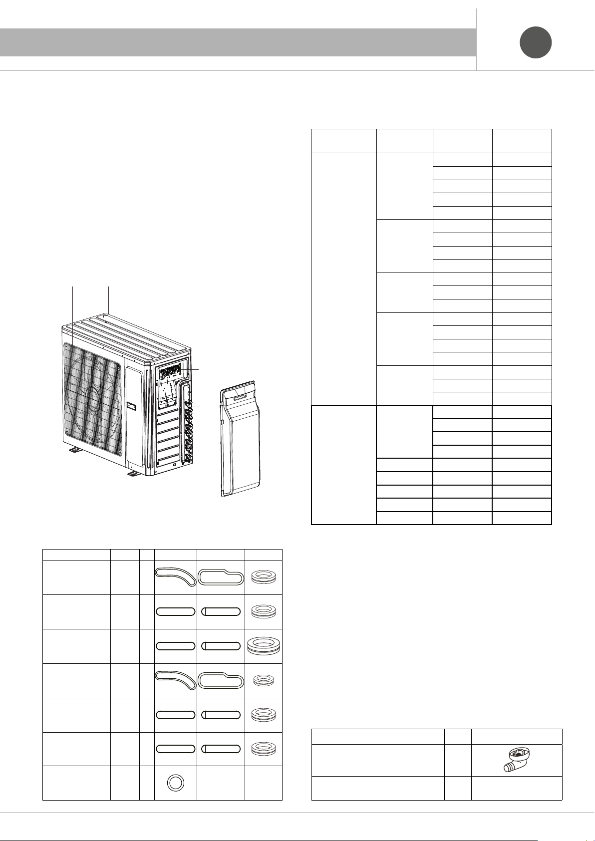
1.2 Unità esterna
Griglia ingresso aria.
Griglia uscita aria.
Collegamento elettrico.
Collegamento tubazioni frigorifere.
1.3 Accessori forniti in dotazione all'unità esterna
Descrizione Q.ta
Tappi in gomma
(da posizionare sul
fondo dell’unità)
Tappi in gomma
(da posizionare sul
fondo dell’unità)
Tappi in gomma
(da posizionare sul
fondo dell’unità)
Tappi in gomma
(da posizionare sul
fondo dell’unità)
Tappi in gomma
(da posizionare sul
fondo dell’unità)
Tappi in gomma
(da posizionare sul
fondo dell’unità)
Tappi in gomma
(da posizionare sul
fondo dell’unità)
XECO
1815E
XECO
2415E
XECO
1415DE
XECO
1815DE
XECO
2415TE
XECO
2815QE
XECO
4216CE
1
1
1
1
1
1
1
1.4 Tabella identificazione prodotti
La seguente tabella serve ad identificare le singole unità acquistate:
Unità Tipo
Interne A parete 07 XECO-0715W
Canalizzata 09 XECO-0915D
Cassette 12 XECO-1215C
Pavimento /
soffitto
Console 09 XECO-0915K
Esterne Single 09 XECO-0915E
Multi x2 14 XECO-1415DE
Multi x2 18 XECO-1815DE
Multi x3 24 XECO-2415TE
Multi x4 28 XECO-2815QE
Multi x5 42 XECO-4216CE
Descrizione
Curvetta di scarico 1
Manuale installazione ed uso dell'unità esterna
Grandezza
kBtu
09 XECO-0915W
12 XECO-1215W
18 XECO-1815W
24 XECO-2415W
12 XECO-1215D
18 XECO-1815D
24 XECO-2415D
18 XECO-1815C
24 XECO-2415C
09 XECO-0915F
12 XECO-1215F
18 XECO-1815F
24 XECO-2415F
12 XECO-1215K
18 XEC O-1815K
12 XECO-1215E
18 XECO-1815E
24 XECO-2415E
Q.ta
1
Modello
ITIT
4

2. AVVERTENZE
Spe-
gnere
Spe-
gnere
ITIT
2.1 Attenzioni e pericoli
Prima di utilizzare il climatizzatore leggere attentamente il presente
manuale di istruzioni. Il produttore declina ogni responsabilità per eventuali danni derivanti dalla non osservanza delle seguenti avvertenze.
Dopo aver letto questo manuale assicurarsi di farlo leggere anche a coloro che utilizzeranno l’unità.
L’utente deve tenere a portata di mano questo manuale e deve consegnarlo a coloro che eseguono le riparazioni o che traslocano l’unità.
Inoltre, nel caso in cui ci sia un cambio di proprietà, rendere disponibile il
manuale per il nuovo utente.
Assicurarsi di osservare rigorosamente i seguenti importanti Avvisi
per la sicurezza.
L’apparecchio non è destinato a essere usato da persone (bambini compresi) le cui capacità fisiche, sensoriali o mentali siano ridotte, oppure con mancanza di esperienza o di conoscenza, a meno che esse abbiano potuto beneficiare, attraverso l’intermediazione di una persona
responsabile della loro sicurezza, di una sorveglianza o di istruzioni riguardanti l’uso dell’apparecchio. I bambini devono essere sorvegliati
per sincerarsi che non giochino con l’apparecchio.
Questo apparecchio può essere usato da bambini di età pari o superiore a 8 anni e persone con ridotte capacità fisiche, sensoriali o mentali
o con mancanza di esperienza e conoscenza, se sotto supervisione o dietro istruzioni relative all’uso dell’apparecchio in modo sicuro e se
comprendono i potenziali pericoli. Non lasciare giocare i bambini con l’apparecchio. pulizia e manutenzione utente non devono essere eseguite da bambini senza supervisione.
Non installare il climatizzatore in locali dove si possano verificare
fughe di gas o altre sostanze infiammabili in prossimità delle unità.
SIGNIFICATO DEI SIMBOLI
Indica che l'azione deve essere evitata.
Indica che devono essere seguite istruzioni
importanti.
Indica una parte alla quale deve essere fornita la
messa a terra.
L’installazione ed eventuali manutenzioni devono essere eseguite
solamente da personale qualificato.
Non usate l’interuttore di riserva dell’unità con le mani bagnate. Non appoggiare vasi di fiori o contenitori d’acqua sopra l’unità
Controllare la solidità del fissaggio del climatizzatore.
Non appoggiare oggetti e non salire sull’unità
Non indirizzare il flusso dell’aria direttamente sulle persone, piante
e animali.
Non sostare a lungo sotto il getto d’aria fredda e non permettere
alla temperatura d’ambiente di diminuire troppo. Diversamente si
possono subire malori o danni alla salute.
Non smontare la griglia dell’unità esterna.
L’esposizione del ventilatore è molto pericolosa poichè potrebbe
ferire le persone.
5

2. AVVERTENZE
ITIT
Prima di qualsiasi intervento di manutenzione togliere l’alimentazione al climatizzatore.
Evitare di bloccare le griglie di entrata e uscita dell’aria.
Questo potrebbe ridurre le prestazioni o causare danni al climatizzatore.
Evitare l’utilizzo di apparecchi di riscaldamento in prossimità del
climatizzatore.
Utilizzare il climatizzatore solo per climatizzare il locale.
Non usare il condizionatore per altri scopi, es. conservazione e
protezione di cibo, animali, piante, strumenti di precisione come
anche opere d’arte, perché la qualità di questi beni ne sarebbe
compromessa.
Non mettere le dita o altri oggetti nelle prese/uscite dell’aria e nel
deflettore oscillante mentre il condizionatore è in funzione. L’alta
velocità della ventola è molto pericolosa e può provocare lesioni.
Scegliere la temperatura ambiente più adatta.
Attenzione a locali occupati da bambini, ammalati e/o anziani.
Non versare o spruzzare acqua sul climatizzatore. Non installare il climatizzatore in prossimità di fonti eccessive di
vapore (acqueo, olii, ecc.)
Se si riscontrano fenomeni anomali (ad esempio odore di bruciato), togliere immediatamente l’alimentazione elettrica e rivolgersi
al rivenditore per istruzioni sul da farsi. In tal caso, continuare a
utilizzare il condizionatore potrebbe causare danni e generare il
rischio di folgorazione e di incendio.
Usare solo fusibili dell’amperaggio appropriato.
(Mai usare pezzi di cavo/filo per effettuare sostituzioni provvisorie.
Questo potrebbe non solo danneggiare l’unità ma anche causare
un incendio).
6

3. INFORMAZIONI IMPORTANTI
Kg
B
Kg
Kg
11
=
=
B
C
Kg
Kg
Kg
11
=
22
=
B
C
D
F
A
ITIT
3.1 Conformità ai regolamenti
I climatizzatori sono conformi alle direttive europee:
2004/108/CE relativa alla compatibilità elettromagnetica.
2006/95/CE relativa alla bassa tensione.
2002/96/CE RAEE riguardante i rifiuti di apparecchiature elettriche ed elettroniche.
2011/65/EU RoHS sulla restrizione d’uso di sostanze inquinanti negli
apparecchi elettrici ed elettronici.
2009/125/EC COMMISSION REGULATION (EU) No 206/2012
in merito alle specifiche per la progettazione ecocompatibile dei condizionatori d’aria e dei ventilatori.
2010/30/EU COMMISSION DELEGATED REGULATION (EU) No
626/2011 per quanto riguarda l’etichettatura indicante il consumo d’ener-
gia dei climatizzatori d’aria.
3.2 Grado di protezione degli involucri
(Codice IP).
Unità interna IP20
= Protetto contro la penetrazione di corpi solidi estranei: ≥12.5 mm
2
(contro l’accesso a parti pericolose col dito).
0 = Non protetto contro l’acqua.
Unità esterna
IP24
2 = Protetto contro la penetrazione di corpi solidi estranei: ≥12.5 mm
(contro l’accesso a parti pericolose col dito).
4 = Protetto contro la penetrazione di acqua con effetti dannosi: spruzzi
d’acqua.
3.4 Informazioni importanti sul refrigerante
utilizzato
Questo prodotto contiene gas fluorurati ad effetto serra inclusi
Protocollo di Kyoto. Non liberare tali gas nell'atmosfera.
Tipo di refrigerante:
Valore GWP* =
GWP* = potenziale di riscaldamento globale
Compilare con inchiostro indelebile
la carica refrigerante di fabbrica del prodotto
=
11
22
la carica di refrigerante totale
L'etichetta compilata deve essere applicata in posizione visibile
sull'unità esterna.
A contiene gas fluorurati ad effetto serra inclusi nel protocollo di
B carica di refrigerante di fabbrica del prodotto: vedi targhette con il
C quantità di refrigerante aggiuntiva per le tubazioni.
D carica di refrigerante totale.
E unità esterna.
F cilindro del refrigerante e collettore di carica.
la quantità di refrigerante aggiuntiva per le tubazioni
=+
2211
Kyoto.
nome dell'unità.
R410A
2084,5
nel
3.3 Limiti di funzionamento
Gamma utile delle temperature ambiente:
VALORI UNITA' ESTERNE
Temperatura esterna ( bulbo umido )
Unità esterna Raffrescamento °C Riscaldamento °C
XECO-0915E -15÷43 -20÷24
XECO-1215E -15÷43 -20÷24
XECO-1815E -15÷43 -20÷24
XECO-2415E -15÷43 -20÷24
XECO-1415DE -15÷43 -20÷24
XECO-1815DE -15÷43 -20÷24
XECO-2415TE -15÷43 -20÷24
XECO-2815QE -15÷43 -20÷24
XECO-4216CE -5÷48 -15÷27
E
R 410 A
=
11
22
=
11
Questo prodotto contiene gas fluorurati ad effetto serra inclusi
ITIT
nel Protocollo di Kyoto. Non liberare tali gas nell’atmosfera.
This product contains fluorinated greenhouse gases covered
GBGB
by the Kyoto Protocol. Do not vent into the atmosphere.
Este producto contiene gas fluorado con efecto invernadero incluidos
ESES
en el protocolo di Kyoto. No vierta este tipo de gas a la atmosfera.
Ce produit contient des gaz fluorés à effet de serre, prévus
FRFR
par le protocole de Kyoto.
Ne pas laisser les gaz s’échapper dans l’atmosphére.
Dieses Produkt enthält fluorierte Treibhausgase, die durch
DEDE
das Kyoto-Protokoll abgedeckt werden.
Lassen Sie Gase nicht in die Atmosphäre ab.
22
=+
2211
B
Kg
C
Kg
D
Kg
Este produto contém gases fluorados com efeito cobertos
PTPT
no Protocolo de Kyoto. Não libertar para a atmosfera.
7

3. INFORMAZIONI IMPORTANTI
ITIT
3.5 Estratto della scheda di sicurezza refrigerante
Gas refrigerante R 410 A
GWP 2087,5
Denominazione 50% Difluorometano
50% Pentafluoroetano
Indicazioni dei pericoli
Maggiori pericoli Asfissia
Pericoli specifici La rapida evaporazione può causare congelamento
Misure di pronto soccorso
Informazione generale Non somministrare alcunchè a persone svenute
Inalazione Trasportare all’aria aperta.
Ricorrere all’ossigeno o alla respirazione artificiale se necessario.
Non somministrare adrenalina o sostanze similari.
Contatto con gli occhi Sciacquare accuratamente con acqua abbondante per almeno 15 min e rivolgersi ad un medico
Contatto con la pelle Lavare subito abbondantemente con acqua.
Togliersi di dosso immediatamente gli indumenti contaminati.
Misure antincendio
Mezzi di estinzione Qualunque
Pericoli specifici Aumento della pressione
Metodo specifici raffreddare i contenitori con spruzzi d’acqua
Misure in caso di fuoriuscita accidentale
Precauzioni individuali Evacuare il personale in aree di sicurezza
Prevedere una ventilazione adeguata
Usare mezzi di protezione personali
Precauzioni ambientali Evapora
Metodi di pulizia Evapora
Manipolazione e stoccaggio
Manipolazione Assicurare un sufficiente ricambio di aria e/o
misure/precauzioni tecniche un’aspirazione negli ambienti di lavoro
Consigli per l’utilizzo sicuro Non respirare vapori o aereosol
Stoccaggio Chiudere accuratamente e conservare in un luogo fresco, asciutto e ben ventilato.
Conservare nei contenitori originali.
Prodotti incompatibili: esplosivo, ateriali infiammabili, Organic peroxide
Controllo della esposizione /protezione individuale
Parametri di controllo AEL (8-h TWA) = 1000 ml/m³
per ciascuno dei due componenti
Protezione respirartoria Per il salvataggio e per lavori di manutenzione in serbatoi usare un apparato respiratorio autonomo
I vapori sono più pesanti dell’aria e possono provocare soffocamento riducendo l’ossigeno
disponibile per la respirazione
Protezione dagli occhi Occhiali di sicurezza
Protezione delle mani Guanti in gomma
Misure di igiene Non fumare
Proprietà fisiche e chimiche
Colore Incolore
Odore Simile all’etere
Punto di ebollizione - 51.6 °C a pressione atmosferica
Punto di accensione Non si infiamma
Densità relativa 1.063 Kg/l a 25 °C
Solubilità nell’acqua 2.8 g/l a 25 °C a pressione atmosferica
Stabilità e reattività
Stabilità Nessuna reattività se impiegato con le apposite istruzioni
Materie da evitare Metalli alcalini, metalli alcalino terrosi, sali di metallo granulato, Al, Zn, Be, ecc. in polvere
Prodotti di decomposizione pericolosi Acidi alogeni, tracce di alogenuri di carbonile, ALC
Tossicità acuta (R32) LC50/inalazione/4 ore/su ratto = 760 l/m³
(R125) LC50/inalazione/4 ore/su ratto = 800 l/m³
Effetti collaterali Inalazione di vapore ad alta concentrazione può produrre asfissia o aritmia cardiaca, polso irregolare,
palpitazioni, circolazione inadeguata e anche arresto cardiaco.
Tossicità a lungo termine Non ha mostrato effetti cancerogeni, teratogeni o mutageni negli esperimenti su animali
Informazioni ecologiche
Potenza di riscaldamento globale HGWP (R11 = 1) R 125: 0.70 - R 32: 0.15
Potenza di depauperamento dell’ozono ODP (R11 = 1) 0
Condizioni sullo smaltimento
Utilizzabile con ricondizionamento
8

4. MOVIMENTAZIONE E TRASPORTO
Per la movimentazione delle unità utilizzare le apposite maniglie
pretranciate sui lati corti degli imballi e attenersi alle leggi vigenti per la
sicurezza sul lavoro del luogo di installazione.
L’unità esterna, e le unità interne di grossa taglia, devono essere
movimentate da due persone.
Imballo dell’unità interna Imballo dell’unità esterna
ITIT
Maniglie pretranciate
Maniglie pretranciate
Le operazioni di disimballo devono essere eseguite con cura, al fine di non
danneggiare l’involucro delle unità, se si opera con coltelli o taglierini per
aprire l’imballo in cartone.
Dopo aver tolto l’imballo assicurarsi dell’integrità delle unità.
In caso di dubbio non utilizzare l’apparecchio e rivolgersi al personale
tecnico autorizzato.
Maniglie pretranciate
Maniglie pretranciate
Attenzione!
Verificare che le due unità costituenti il climatizzatore non abbiano subito
danni durante il trasporto.
Nel caso fosse necessaria la contestazione contattare il trasportatore
per l’accertamento tempestivo del danno e delle responsabilità.
Prima di eliminar e gli imballi assicurarsi che tutti gli accessori in dotazione
siano stati tolti dagli stessi.
9

5. POSIZIONAMENTO DELL'UNITÀ
> 500 mm
> 500 mm
> 1000 mm
> 500 mm
ITIT
Il condizionatore deve essere collocato in un luogo ben ventilato e facilmente
accessibile.
Il condizionatore non deve essere collocato nei luoghi che seguono:
(a) Luoghi in cui sono presenti oli di macchine o fumi di altri oli.
(b) Lungo la costa dove nell’aria è presente un’alta concentrazione di sale.
(c) Vicino a risorgive ad alto contenuto di gas solforici.
(d) In aree con alta fluttuazione della tensione, e.g. fabbriche, eccetera.
5.1 Posizionamento dell’unità esterna
Evitare, se possibile, l’esposizione dell’unità ai
raggi solari, in particolare nelle ore del primo
pomeriggio. In caso contrario provvedere ad
installare una protezione idonea che non ostacoli
la libera circolazione dell’aria.
Porre particolare attenzione alle precipitazioni
nevose, compresa la caduta della neve dalle
falde del tetto, che potrebbe ostacolare la circolazione dell’aria.
Evitare un posizionamento in corrispondenza di
zone che possano accentuare gli effetti negativi
degli agenti atmosferici quali scarichi di grondaia
o scarichi pluviali.
Scegliere una posizione nella quale il rumore
ed il getto d’aria non rechino danni o disagi alle
persone, animali o piante.
(e) In veicoli o imbarcazioni.
(f) In cucine con molti fumi di oli ed alta percentuale d’ umidità.
(g) Vicino a macchine che emettono onde elettromagnetiche.
(h) Luoghi con fumi acidi o alcalini.
Le attrezzature TV, radio, acustiche devono stare ad una distanza minima di
1 m dall’unità interna, esterna, cavo d’alimentazione, cavi di collegamento,
tubi; diversamente, le immagini possono essere disturbate e si possono
creare rumori.
Scegliere la posizione che favorisca la circolazione dell’aria e che faciliti lo smaltimento
dell’acqua di condensazione.
Assicurare il rispetto delle “distanze minime
funzionali”.
5.2 Distanze minime funzionali unità esterna
10

5. POSIZIONAMENTO DELL'UNITÀ
5.3 Distanze fra le unità
ITIT
Dislivello
Modello
XECO-0915E - 10 15 15 5 20
XECO-1215E - 10 20 20 5 20
XECO-1815E - 10 25 25 5 20
XECO-2415E - 10 25 25 5 50
XECO-1415DE 5 5 10 20 10 20
XECO-1815DE 5 5 10 20 10 20
XECO-2415TE 10 10 20 60 30 20
XECO-2815QE 10 10 20 70 40 20
XECO-4216CE 7.5 15 25 80 50 22
Nota:
più corto è il tubo del refrigerante, migliori sono le prestazioni. Collegare in
modo che il tubo sia il più corto possibile. La lunghezza minima consentita
per stanza è di 3 m.
Multi
Di seguito sono indicati i dislivelli massimi consentiti tra le unità interne ed
esterne.
massimo
tra U. Interna e
U. Interna
m m m m m g/m
Dislivello
massima
tra U. Interna
e U. Esterna
Distanza
massima
tra U. Interna
e U. Esterna
Lunghezza
massima
totale
dei tubi
Lunghezza
totale
standard (m)
Carica addizionale di
gas oltre la lunghezza
totale standard (g/m)
Unità interne
Dislivello:
15 m
max
Se l’unità esterna è più alta delle unità interna.
Dislivello:
15 m
max
Dislivello:
7.5 m
max
Unità interne
Dislivello:
7.5 m
max
Unità esterna
Unità esterna
Dislivello:
7.5 m
max
Dislivello:
15 m
Se l’unità interna è più alta delle unità esterna.
max
Unità interne
Unità esterna
Se l’unità esterna è più alta delle unità interne ma più bassa di una o più unità.
11

5. POSIZIONAMENTO DELL'UNITÀ
5.4 Dati dimensionali unità esterna
D
B
ITIT
F
C
A
Modello A B C D E F G
XECO-0915E 776 540 320 712 257 510 286
XECO-1215E 776 540 320 712 257 510 286
XECO-1815E 963 700 396 892 341 560 368
XECO-2415E 1000 790 427 920 370 610 395
XECO-1415DE 903 596 378 838 303 550 340
XECO-1815DE 963 700 396 892 341 560 368
XECO-2415TE 1001 790 427 924 370 610 395
XECO-2815QE 1001 790 427 924 370 610 395
XECO-4216CE 1087 1103 440 1015 362 631 401
G
E
12

6. INSTALLAZIONE DELL'UNITÀ ESTERNA
A
A
A
09 - 12 - 14 - 18 - 42 kBtu
24 - 28 kBtu
Le attività d’ installazione e manutenzione eseguite sui condizionatori d’aria, possono essere effettuate soltanto da personale e
imprese in possesso del certificato appropriato conformemente al
regolamento (CE) n. 303/2008 che stabilisce, in conformità al regolamento (CE) n. 842/2006 del Parlamento europeo e del Consiglio,
i requisiti minimi delle imprese e del personale per quanto concerne le apparecchiature fisse di refrigerazione, condizionamento
d’aria e pompe di calore contenenti taluni gas fluorurati ad effetto
serra.
- L'installazione deve essere eseguita da personale qualificato e autorizzato.
- Non tentare di installare l'apparecchio da soli.
- Per eventuali riparazioni contattare il Servizio Assistenza. Le riparazioni
di carattere elettrico devono essere eseguite da elettricisti qualificati.
- Operazioni non adeguate possono provocare gravi danni all'utente.
- La lista dei centri assistenza è disponibile nel sito web
www.emmeti.com.
La corretta installazione del climatizzatore ne garantisce l’efficiente
funzionamento.
Vi invitiamo pertanto a seguire attentamente le indicazioni sul posizionamento, l’installazione, i collegamenti e il collaudo presenti in questi
manuali.
ITIT
minimo 400 mm
ATTENZIONE
Pericolo taglio: uso di guanti adatti.
Se ne ricorrono le condizioni rispettate le norme per i lavori in quota.
6.1 Installazione dell’unità esterna
- Montare sotto l’unità esterna i gommini antivibranti e collocare l’unità sopra un rialzo di almeno 10 cm come in Fig. A.
- Assicurarsi della stabilità e del livellamento della superficie ove poggiare l’unità.
- In caso di installazione di unità esterne in batteria è indispensabile
assicurare fra le unità distanze tali da non limitare la circolazione
dell’aria alla singola unità e da non rendere difficoltosi gli interventi
di manutenzione (Fig. B).
- In caso di installazione sotto tetto o similari attenersi alle indicazioni
di figura C.
Fig. A
A = 10 cm
minimo 400 mm
Fig. C
6.2 Tubazione di scarico condensa
L’unità esterna ha nella parte inferiore del telaio un foro che, tramite il
raccordo conico in dotazione, scarica l’acqua di condensazione.
- L’attacco del portagomma è ad innesto (Fig. A).
- La tubazione di scarico condensa dovrà essere leggermente in pendenza per consentire il deflusso naturale.
- Si consiglia di utilizzare un tubo in plastica sufficientemente rigido per
evitare eventuali schiacciamenti dello stesso.
Scarico condensa
Fig. B
A = mimimo 60 cm
Nota:
le staffe di fissaggio sono accessori forniti separatamente.
Fig. A
Attenzione!
Posizionare lo scarico dell’acqua di condensa in modo da non arrecare
danni a persone o cose.
È consigliabile avere la possibilità di un controllo visivo dello scarico
al termine della tubazione oppure inserire uno spezzone trasparente
nella tubazione stessa quando questa confluisce in uno scarico non
ispezionabile.
13

6. INSTALLAZIONE DELL'UNITÀ ESTERNA
ITIT
6.3 Tubazioni circuito frigorifero
Le connessioni per le tubazioni frigorifere sono con tenuta a cartella e bocchettone.L’unità esterna contiene tutta la carica del sistema refrigerante ed è dotata di
valvole con connessione a bocchettone e presa di servizio.
Modello Linea liquido Linea gas
Unità Tipo
A parete
Canalizzata
Interne
Cassette
Pavimento / soffitto
Console
Single
Esterne
Multi x2 14 XECO-1415DE 2 x 1/4" 2 x 6.35 2 x 3/8" 2 x 9.52
Multi x2 18 XECO-1815DE 2 x 1/4" 2 x 6.35 2 x 3/8" 2 x 9.52
Multi x3 24 XECO-2415TE 3 x 1/4" 3 x 6.35 3 x 3/8" 3 x 9.52
Multi x4 28 XECO-2815QE 4 x 1/4" 4 x 6.35 4 x 3/8" 4 x 9.52
Multi x5 42 XECO-4216CE
Grandezza
kBtu
07 XECO-0715W 1/4" 6.35 3/8" 9.52
09 XECO-0915W 1/4" 6.35 3/8" 9.52
12 XECO-1215W 1/4" 6.35 3/8" 9.52
18 XECO-1815W 1/4" 6.35 1/2" 12.7
24 XECO-2415W 1/4" 6.35 5/8" 15.88
09 XECO-0915D 1/4" 6.35 3/8" 9.52
12 XECO-1215D 1/4" 6.35 3/8" 9.52
18 XECO-1815D 1/4" 6.35 1/2" 12.7
24 XECO-2415D 3/8" 9.52 5/8" 15.88
12 XECO-1215C 1/4" 6.35 3/8" 9.52
18 XECO-1815C 1/4" 6.35 3/8" 9.52
24 XECO-2415C 1/4" 6.35 3/8" 9.52
09 XECO-0915F 1/4" 6.35 3/8" 9.52
12 XECO-1215F 1/4" 6.35 3/8" 9.52
18 XECO-1815F 1/4" 6.35 1/2" 12.7
24 XECO-2415F 3/8" 9.52 5/8" 15.88
09 XECO-0915K 1/4" 6.35 3/8" 9.52
12 XECO-1215K 1/4" 6.35 3/8" 9.52
18 XECO-1815K 1/4" 6.35 3/8" 9.52
09 XECO-0915E 1/4" 6.35 3/8" 9.52
12 XECO-1215E 1/4" 6.35 3/8" 9.52
18 XECO-1815E 1/4" 6.35 1/2" 12.7
24 XECO-2415E 1/4" 6.35 5/8" 15.88
Modello Ø inch Ø mm Ø inch Ø mm
3 x 1/4" + 2 x
3/8"
3 x 6.35 + 2 x
9.52
2 x 9.52 + 2 x
12.7 + 1 x 5/8"
12.7 + 1 x 15.88
2 x 9.52 + 2 x
Attenzione!
Usare solamente tubo in rame del tipo CU DHP secondo UNI EN 12735-1,
ricotto, nuovo, sgrassato e deossidato.
Non è idoneo il tubo di rame per servizi termosanitari.
6.3.1 Esecuzione delle linee frigorifere
Percorso e piegatura delle tubazioni
- Determinare il percorso dei tubi con il minor numero di curve possibile.
- Eseguire le curve con idoneo piegatubi onde evitare pericolosi schiacciamenti.
- Per curve a grande raggio utilizzare, come appoggio, delle superfici
cilindriche agendo con delicatezza.
Attenzione!
Non piegare il tubo di rame più di 3 volte nello stesso punto onde evitare
la formazione di pericolose cricche.
14
Taglio e svasatura del tubo
- Tagliare il tubo di rame alla lunghezza prevista, usando un tagliatubi; è
opportuno che in prossimità dell’unità esterna vi sia un tratto rettilineo
adeguato in modo da consentire l’eventuale rifacimento della cartella;
- Togliere la sbavatura all’estremità del tubo con uno svasatore. Questa
operazione è molto importante per ottenere una cartellatura di buona
qualità (Fig. A);
Svasatore
Fig. A
Attenzione!
Quando procedete alla svasatura tenete l’estremità del tubo rivolto verso
il basso evitando di far cadere sfridi all’interno dello stesso.
I bocchettoni posti sui raccordi delle unità vanno tolti immediatamente
prima dell’uso operando in modo che i rubinetti rimangano aperti per il
minor tempo possibile.

6. INSTALLAZIONE DELL'UNITÀ ESTERNA
ITIT
6.3.2 Isolamento delle tubazioni
Prima di eseguire le operazioni di cartellatura del tubo è indispensabile
isolarlo e poi inserire i bocchettoni sul tubo (Fig. B).
Fig. B
Usare un tubo isolante in materiale plastico espanso a cellule chiuse
impermeabile al vapore acqueo e dello spessore non inferiore a 9 mm.
(Fig. C).
Isolante
Fig. C
Avvolgere eventuali tratti scoperti con fascia adesiva avente caratteristiche uguali all’isolante utilizzato per le tubazioni.
6.3.4 Connessione dei tubi ai raccordi
Connettere le tubazioni ai raccordi delle unità.
Per il serraggio stringere i bocchettoni con una coppia pari a:
Diametro Spessore superficie
(mm)
1/4’’ ≥ 0.5 15-30 (N·m)
3/8’’ ≥ 0.71 30-40 (N·m)
1/2’’ ≥ 1 45-50 (N··m)
5/8’’ ≥ 1 60-65 (N·m)
3/4’’ ≥ 1 70-75 (N··m)
Olio refrigerante
Chiave a rullino
Coppia di serraggio
(N·m)
Bocchettone
Chiave
dinamometrica
6.3.3 Esecuzione della cartella
La buona esecuzione della cartella è essenziale per la tenuta del raccordo, va pertanto eseguita con particolare cura e con idonea cartellatrice
(Fig. D/E).
Cartellatrice
Fig. D
Esempio di cartellature errate
Profilo inclinato
Criccature
Fig. E
Superficie
danneggiata
Spessore non
costante
6.4 Allacciamento elettrico
I collegamenti elettrici devono essere eseguiti da personale qualificato e
nel rispetto delle normative vigenti nel luogo d’installazione dell’unità di
condizionamento dell’aria.
Il collegamento deve essere preceduto da un’accurata verifica di compatibilità tra la linea di alimentazione elettrica e le caratteristiche dell’unità
che si intende collegare.
Nella linea d’alimentazione elettrica dell’unità è obbligatorio prevedere
un interruttore (differenziale) bipolare con una separazione dei contatti di
almeno 3 mm in ciascun polo.
Attenzione!
Prima di effettuare qualsiasi intervento sulle unità accertarsi che sia stata
tolta l’alimentazione elettrica generale.
Prima di interrompere l’alimentazione dall’interruttore spegnere il climatizzatore con il telecomando.
Collegare il cavo di messa a terra
Il cavo di messa a terra non deve essere collegato alle
tubazioni del gas, dell’acqua, al parafulmini, alla linea
telefonica; la scorretta messa a terra può provocare scariche elettriche.
È importante applicare olio refrigerante sulle superfici di accoppiamento
della cartella e del raccordo prima del collegamento.
Con questa operazione si riducono le possibilità di eventuali perdite di gas.
Attenzione!
Utilizzare esclusivamente olio sintetico nei climatizzatori caricati con
refrigerante R 410 A.
15

6. INSTALLAZIONE DELL'UNITÀ ESTERNA
6.4.1 Controlli preliminari
- Controllare che l’impianto elettrico, destinato all’alimentazione del
climatizzatore, abbia tensione e frequenza corrispondente a quella
richiesta dalle unità.
- Controllare che la potenza elettrica di cui dispone l’utente sia sufficiente al funzionamento del climatizzatore e degli altri apparecchi elettrici
presenti.
6.4.2 Alimentazione delle unità
L'alimentazione viene portata sull'unità esterna.
Utilizzare una fonte di alimentazione ad uso esclusivo del climatizzatore
con interruttore magnetotermico/differenziale dedicato.
Fig. A
Collegamenti elettrici in un esempio di installazione
Alimentazione
Nastratura alluminata
Tubazioni frigorifere
Scarico condensa unità interna
Cavo elettrico di collegamento
tra le unità
- Prevedere l’uso di una guaina di protezione dei cavi esposti all’esterno.
- È consigliabile predisporre i cavi con un percorso antigoccia onde
evitare possibili infiltrazioni d’acqua nell’unità esterna.
- Unire il cavo elettrico di collegamento delle due unità alle tubazioni
refrigeranti e avvolgerle con un nastro rinforzato, possibilmente alluminato (Fig. B).
- Qualora il cavo non possa essere solidale con le tubazioni, provvedere
ad un idoneo ancoraggio a parete mediante fissacavo o fascette.
ITIT
Fig. B
Interruttore
magnetotermico
differenziale
Fig. A
6.4.3 Cavi di alimentazione e di collegamento
- Tutti i cavi di alimentazione e di collegamento devono essere approvati
in base allo standard IEC e per lunghezze fino a 15 m deve avere una
sezione non inferiore a:
Modello Cavo di alimentazione
Cavo di collegamento
Unità Esterna - Interna
XECO-0915E 3 x 2.5 mm
XECO-1215E 3 x 2.5 mm
XECO-1815E 3 x 2.5 mm
XECO-2415E 3 x 2.5 mm
XECO-1415DE 3 x 2.5 mm
XECO-1815DE 3 x 2.5 mm
XECO-2415TE 3 x 2.5 mm
XECO-2815QE 3 x 2.5 mm
XECO-4216CE 3 x 4 mm
2
2
2
2
2
2
2
2
2
4 x 1.5 mm
4 x 1.5 mm
4 x 1.5 mm
4 x 1.5 mm
4 x 1.5 mm
4 x 1.5 mm
4 x 1.5 mm
4 x 1.5 mm
4 x 1.5 mm
2
2
2
2
2
2
2
2
2
6.4.4 Collegamento alla morsettiera dell'unità esterna
- Togliere le due viti di fissaggio e rimuovere il coprimorsettiera (Fig. C).
Fig. C
- Allentare le viti ed inserire completamente le estremità del cavo nel
blocco terminali, poi stringere le viti.
70 mm
10 mm
- Utilizzare un cavo multipolare del tipo N07RN-F
- Per lunghezze superiori ai 15 m adottare le sezioni standard immediatamente superiori, sempre verificando che in ogni caso la caduta di
tensione sotto carico sia inferiore al 3% della tensione di alimentazione.
- Se un cavo è danneggiato deve essere sostituito da personale del
servizio assistenza o comunque da personale qualificato.
- Tutti i cavi devono avere il certificato di conformità.
16
10 mm
50 mm
- Tirare leggermente il cavo per accertarsi che i cavi siamo stati inseriti e
fisati in modo appropriato.
- Dopo avere collegato i cavi non dimenticare mai di stringerli al pressacavo.

6. INSTALLAZIONE DELL'UNITÀ ESTERNA
ITIT
Morsettiera unità esterna Single
2
N(1)
3
Pressacavo
Cavo di collegamento
Cavo di alimentazione
Collegamenti con l’unità interna:
2 3
N(1)
Morsettiera unità esterna Multi
E
Cavo
di collegamento
L
Cavo
di alimentazione
A B
Cavo
di collegamento
Cavo
di collegamento
C D
L
Cavo
di collegamento
Cavo
di collegamento
Collegamenti con le unità interne: XECO-1415DE e XECO-1815DE (x2)
Unità esterna
L
N
Unità
LN
Esterna
N
Unità
Interna
L
SINGLE 9 - 12
Alimentazione
Unità XECO-2415TE (x3)
L
Unità Interna B
Unità Interna A
Unità esterna
Unità
Esterna
2 3 L
NN(1)
SINGLE 18 - 24
N
Alimentazione
L
Unità
Interna
UNITÀ XECO-2815QE (x 4)
Unità Interna D
XT5 XT4 XT3 XT2 XT1
Unità Interna C
Unità Interna B
Unità Interna A
Unità esterna
UNITÀ XECO-4216CE (x 5)
Unità Interna E
Unità Interna D
Unità Interna C
Unità Interna B
Alimentazione
L
N
Unità Interna A
L
Unità internaAUnità internaBUnità interna
C
Alimentazione
L
N
XT5 1TX2TX3TX4TX6TX
Unità esterna
17

7. CARICA E COLLAUDO DELL'IMPIANTO
ITIT
7.1 Vuoto e carica
del circuito frigorifero con R410A
- Le operazioni sotto indicate devono essere eseguite dopo aver tolto
l’alimentazione elettrica al climatizzatore.
- L’unità esterna contiene una carica di R410A adatta per tubazioni fino
ai 5 metri di lunghezza.
- Non miscelare sostante diverse dal refrigerante specificato (R410A) nel
ciclo di refrigerazione.
- Nel caso si verifichi una perdita di refrigerante, ventilare il più possibile
la stanza.
- Il refrigerante R410A, come anche antri refrigeranti, devono essere
sempre recuperati e non devono mai essere smaltiti direttamente
nell’ambiente.
- Usare una pompa per il vuoto apposita per R410A. L’uso della stessa
pompa per il vuoto per vari tipi di refrigeranti può danneggiare la
pompa o l’unità
- Utilizzare strumenti (gruppo manometrico, flessibili e pompa vuoto) dedicati esclusivamente ad impianti funzionanti con refrigerante R 410A.
- Non sostituire o mescolare un gas con un’altro in quanto non compatibili.
- Per la carica a R410A è tassativo immettere il refrigerante in forma
liquida.
7.1.1 Procedura di vuoto e carica
- Serrare i raccordi (Fig. A) come indicato al paragrafo 6.3.4.
- Collegare alla presa di servizio (Fig. A) la pompa per il vuoto me diante
il gruppo manometrico portatile.
- Mantenerla in moto fino al raggiungimento di un vuoto pari o minore a
1 mBar, se la pompa è dotata di vacuometro, o per almeno 25 minuti in
mancanza dello strumento di controllo.
- Chiudere il rubinetto del gruppo manometrico collegato alla pompa e
spegnere la stessa.
- Se il gruppo manometrico è dotato di vacuometro attendere almeno 5
minuti per verificare che il vuoto nell’impianto sia mantenuto, altrimenti
ricercare la causa della perdita.
- Per linee oltre i 5 metri è indispensabile caricare il circuito mediante
cilindro dosatore o bilancia elettronica con una quantità di R 410 A
proporzionale alle tubazioni usate e alla loro lunghezza come indicato
nella tabella a pagina 11.
Nota:
Per determinare la carica addizionale si considera la lunghezza di una
sola linea.
Attacco
linea
flessibile
Fig. A
Liquido
Gas
Gruppo manometrico
Linea flessibile
Dopo l’eventuale carica aggiuntiva di gas refrigerante:
- Togliere i tappi (Fig. A) e con l’apposita chiave aprire le valvole (è buona
tecnica aprire tutto, poi chiudere 1/2 giro);
- Rimettere i tappi (Fig. A) e chiuderli a fondo;
- Verificare con il cercafughe le eventuali perdite dei raccordi.
- Sconnettere dal raccordo (Fig. A) le attrezzature usate e chiudere
accuratamente le prese di servizio con i relativi tappi;
7.1.2 Precauzioni per quando si aggiunge il refrigerante
- Riempire dal tubo del liquido in forma liquida.
- R410A è un refrigerante miscelato, quindi aggiungerlo in forma gassosa
può provocare il cambiamento della composiszione del refrigerante,
impedendo il normale funzionamento.
- Prima di rabboccare, verfificare se la bombola è dotata di sifone.
(Ci deve esser e una dicitura del tipo “Sifone per il rabbocco in dot azione”)
Raccordo
Valvola 3 vie
Tappo valvola
Presa di servizio
Tappo presa servizio
Pompa del vuoto
18
Riempimento di una bombola dotata di sifone
La bombola deve stare dritta durante il riempimento.
All’interno c’è un sifone, quindi la bombola non deve
essere capovolta per essere riempita.
Riempimento di altre bombole
Capovolgere a bombola durante il riempimento.

1. DESCRIZIONE DEI COMPONENTI
7. CARICA E COLLAUDO DELL'IMPIANTO
ITIT
7.2 Test di funzionamento
(la prima accensione va fatta assolutamente
in modalità Raffrescamento)
Prima di avviare il test, accertarsi di avere portato a termine correttamente i seguenti lavori:
- Tubature;
- Collegamento dei cavi elettrici;
- Corrispondenza corretta dell’unità interna ed esterna;
- Rabbocco appropriato del refrigerante, se necessario;
- Assicurarsi che tutte le valvole d’arresto siano completamente aperte;
- Verificare che la tensione fornita all’unità esterna ed alle unità interne
sia di 230V.
- Per eseguire il test in modo Raffreddamento, impostare la tem-
peratura minima a 16°C.
- Per eseguire il test in modo Riscaldamento, impostare la tem-
peratura massima a 30°C.
- Testare prima ciascuna unità interna singolarmente sia in
Raffreddamento che in Riscaldamento, quindi testare il funzionamento simultaneo di tutte le unità interne.
- Dopo aver fatto funzionare l’unità per 20 minuti, misurare il
delta T dell’unità interna.
Nota:
se la temperatura ambiente è inferiore a 16°C è impossibile
eseguire il test di funzionamento in modo Raffreddamento con
il telecomando, così come, se la temperatura ambiente è superiore a 30°C, è impossibile eseguire il test di funzionamento in
modo Riscaldamento.
7.3 Recupero refrigerante
Il refrigerante deve sempre essere recuperato in apposite bombole utilizzando l'unità di recupero e seguendo le istruzioni d'uso della stessa.
Nota:
il refrigerante non deve essere liberato in atmosfera come specificato
nel regolamento (CE) n. 2037/2000 del parlamento europeo e del consiglio
Nota:
dopo che l’unità viene spenta, o dopo che viene variata la modalità
di funzionamento, il compressore non si rimette in moto prima di
3 min.
Durante il funzionamento in modo Raffreddamento, si può formare
della brina sull’unità interna o sulle tubazioni.
Far funzionare l’unità secondo quanto riportato nel manuale di
istruzioni. Spiegare all’utente finale il funzionamento del climatizzatore per mezzo del manuale di istruzioni.
Punti da confermare durante il test di funzionamento:
Vi sono perdite di gas dai giunti delle tubazioni?
I giunti delle tubazioni sono stati isolati termicamente?
I collegamenti elettrici delle unità interne e dell’unità esterna
sono corretti?
Il cavo di collegamento tra unità interne ed esterna è fissato
saldamente?
Il drenaggio della condensa avviene in modo corretto?
Il filo di messa a terra è collegato saldamente?
Il voltaggio dell’alimentazione corrisponde a quello previsto
dalle norme vigenti?
Si sentono rumori insoliti?
Il funzionamento in modalità Raffreddamento è normale?
Il sensore temperatura ambiente funziona in modo corretto?
19

1. DESCRIZIONE DEI COMPONENTI
8. SMALTIMENTO
ITIT
8.1 Informazione per la tutela dell'ambiente!
Questa unità contiene gas fluorurati a effetto serra coperti dal
Protocollo di Kyoto. Le operazioni di manutenzione e smaltimento
devono essere eseguite solo da personale qualificato.
Direttiva 2012/19/CE (RAEE): informazioni agli utenti
Questo prodotto é conforme alle Direttive UE 2012/19/CE.
Il simbolo del cestino barrato riportato sotto l'apparecchio
indica che il prodotto, alla fine della propria vita utile, dovendo essere
trattato separatamente dai rifiuti domestici, deve essere conferito
in un centro raccolta differenziata per apparecchiature elettriche ed
elettroniche oppure riconsegnato al rivenditore al momento dell'acquisto
di una nuova apparecchiatura equivalente.
L'utente é responsabile del conferimento dell'apparecchio a fine vita alle
appropiate strutture di raccolta.
L'adeguata raccolta differenziata per l'avvio successivo dell'apparecchio
dismesso al riciclaggio, al trattamento e allo smaltimento ambientale
compatibile contribuisce ad evitare possibili effetti negativi sull'ambiente e sulla salute e favorisce il riciclo dei materiali di cui è composto
il prodotto.Per informazioni più dettagliate inerenti i sistemi di raccolta
disponibili, rivolgersi al servizio locale di smaltimento rifiuti o al negozio
in cui é stato effettuato l'acquisto.
8.3 Norme di smaltimento dell'imballaggio del
nuovo climatizzatore
Tutti i materiali di imballaggio del climatizzatore devono essere smaltiti
senza recare danno all'ambiente. L'imballo di cartone deve essere tagliato
in pezzi e conferito presso una campana raccolta carta. L'involucro di plastica e polistirolo non contiene fluoro o cloro idrocarburi.
Tutti questi materiali possono essere conferiti in discarica e riciclati dopo
un adeguato trattamento. Informatevi presso il vostro Comune circa le
modalità di smaltimento rifiuti.
8.4 Smaltimento delle batterie del telecomando
Le batterie sono state progettate e prodotte con
materiale di alta qualità e i componenti possono essere
riciclati e/o riutilizzati. Il simbolo del cestino barrato
indica che il prodotto (batterie) alla fine della propria
vita utile (esaurite) deve essere separato dai rifiuti
domestici e deve essere conferito in un centro di raccolta
differenziata, come disposto dalla Comunità Europea 2006/66 CE art. 20
e annesso II.
Se sotto il cestino c’è un simbolo chimico , questo indica che le batterie
contengono una certa concentrazione di metallo pesante e sarà indicato
come segue: Hg: mercurio (0,0005%), Cd: cadmio (0,002%), Pb: piombo
(0,004%)
8.2 Norme di smaltimento del vecchio
climatizzatore
Prima di smaltire il vostro vecchio climatizzatore, accertatevi che sia spento
e staccate la spina dalla presa di corrente. Il refrigerante contenuto
all'interno richiede una speciale procedura per lo smaltimento. I materiali
di valore contenuti nel climatizzatore possono essere riciclati, informatevi
presso il vostro Comune o la discarica della vostra città. Fate attenzione
a non danneggiare le tubazioni del climatizzatore prima di conferirlo in
discarica. Contribuite alla salvaguardia dell'ambiente seguendo un metodo
di smaltimento corretto e non inquinante.
20

1. DESCRIZIONE DEI COMPONENTI
9. ANOMALIE DI FUNZIONAMENTO
N° Tipo di anomalia Display Possibili cause
1. Sovrabbondanza di refrigerante.
1 Protezione alta pressione E1
Protezione antighiacciamento unità
2
interna
3 Protezione bassa pressione E3
Protezione alta temperatura di scarico
4
del compressore
5 Protezione sovraccarico E5
2. Scarso scambio termico (scambiatore sporco o scarso ricircolo dell’aria).
3. Temperatura ambiente troppo alta.
1. Scarso scambio termico (scambiatore sporco o scarso ricircolo dell’aria).
E2
2. Motore ventilatore unità interna danneggiato.
1. Insufficienza di refrigerante;
2. Perdita di refrigerante.
1. Sovrabbondanza di refrigerante.
E4
2. Temperatura ambiente troppo alta.
3. Scarso scambio termico (scambiatore sporco o scarso ricircolo dell’aria).
1. Tensione di alimentazione instabile.
2. Tensione di alimentazione bassa.
3. Sovrabbondanza di refrigerante.
4. Temperatura ambiente troppo alta.
5. Scarso scambio termico (scambiatore sporco o scarso ricircolo dell’aria).
ITIT
6 Anomalia di comunicazione E6
7 Modo di funzionamento in conflitto E7
Protezione surriscaldamento batteria
8
condensante
9 Anomalia EEPROM EE Scheda elettronica AP1 unità esterna danneggiata.
10
11
12 Anomalia ponticello C5
13 Recupero refrigerante F0
14
15
16
17
18
Frequenza ridotta persovracorrente
del modulo IPM
Frequenza ridotta per sovratemperatura
del modulo IPM
Anomalia sensore di temperatura ambiente unità interna
Anomalia sensore di temperatura evaporatore unità interna
Anomalia sensore di temperatura ambiente unità esterna
Anomalia sensore di temperatura condensatore unità esterna
Anomalia sensore di temperatura di
scarico unità esterna
1. Cavo di comunicazione tra unità interna ed esterna non connesso correttamente.
2. Comando a filo non connesso correttamente (se installato).
Il modo di funzionamento dell’unità interna è in conflitto col funzionamento dell’unità
esterna.
1. Sovrabbondanza di refrigerante;
E8
2. Scarso scambio termico (scambiatore sporco o scarso ricircolo dell’aria);
3. Temperatura ambiente troppo alta.
1. Verificare l’isolante termico del Modulo IPM e il radiatore (l’unità deve essere
En
disalimentata da almeno 20 min);
2. Scheda elettronica unità esterna danneggiata.
1. Verificare l’isolante termico del Modulo IPM e il radiatore (l’unità deve essere
EU
F1
F2
F3
F4
F5
disalimentata da almeno 20 min);
2. Scheda elettronica AP1 unità esterna danneggiata.
Il ponticello presente nella scheda elettronica dell’unità interna non è inserito corret-
tamente.
L’unità esterna ha ricevuto il segnale per entrare nella funzione di “Recupero refrige-
rante”.
1. Allentamento o falso contatto del sensore di temperatura con la scheda elettronica.
2. Sensore di temperatura danneggiato.
3. Scheda elettronica unità interna danneggiata.
1. Allentamento o falso contatto del sensore di temperatura con la scheda elettronica.
2. Sensore di temperatura danneggiato.
3. Scheda elettronica unità interna danneggiata.
4. La testa del sensore di temperatura non è stata inserita all’interno del tubo di rame.
1. Allentamento o falso contatto del sensore di temperatura con la scheda elettronica.
2. Sensore di temperatura danneggiato.
3. Scheda elettronica unità esterna danneggiata.
1. Allentamento o falso contatto del sensore di temperatura con la scheda elettronica.
2. Sensore di temperatura danneggiato.
3. Scheda elettronica unità esterna danneggiata.
4. La testa del sensore di temperatura non è stata inserita all’interno del tubo di rame.
1. Allentamento o falso contatto del sensore di temperatura con la scheda elettronica.
2. Sensore di temperatura danneggiato.
3. Scheda elettronica unità esterna danneggiata.
4. La testa del sensore di temperatura non è stata inserita all’interno del tubo di rame.
21

1. DESCRIZIONE DEI COMPONENTI
9. ANOMALIE DI FUNZIONAMENTO
N° Tipo di anomalia Display Possibili cause
1. Tensione di alimentazione bassa.
19
20 Frequenza ridotta per sovracorrente F8
21
22
23
24
25 Test a frequenza fissa P0 Visualizzato durante i test a frequenza fissa P0.
26 Test a frequenza fissa P1 Visualizzato durante i test a frequenza fissa P1.
27 Test a frequenza fissa P2 Visualizzato durante i test a frequenza fissa P2.
28 Test a frequenza fissa P3 Visualizzato durante i test a frequenza fissa P3.
29 Test a frequenza fissa P4 Visualizzato durante i test a frequenza fissa P4.
30 Test a frequenza fissa P5 Visualizzato durante i test a frequenza fissa P5.
31 Test a frequenza fissa P6 Visualizzato durante i test a frequenza fissa P6.
32 Test a frequenza fissa P7 Visualizzato durante i test a frequenza fissa P7.
33 Protezione alta temperatura modulo IPM P8
34 Anomalia carica condensatore PU
35 Sbrinamento H1 Funzionamento normale durante la modalità di riscaldamento.
36 Protezione ionizzatore H2
37 Protezione sovraccarico compressore H3
38 Anomalia al sistema H4
Frequenza ridotta per surriscaldamento
batteria condensante
Frequenza ridotta per sovratemperatura
aria di scarico
Frequenza ridotta
per antighiacciamento
unità interna
Tensione troppo elevata per la scheda
elettronica
Tensione troppo bassa per la scheda
elettronica
2. Sovrabbondanza di refrigerante.
F6
3. Temperatura ambiente troppo alta.
4. Scarso scambio termico (scambiatore sporco o scarso ricircolo dell’aria).
1. Tensione di alimentazione bassa.
2. Sovrabbondanza di refrigerante.
3. Temperatura ambiente troppo alta.
4. Scarso scambio termico (scambiatore sporco o scarso ricircolo dell’aria).
1. Temperatura ambiente troppo alta;
F9
2. Insufficienza di refrigerante;
3. Anomalia della valvola d’espansione elettronica.
1. Scarso scambio termico (scambiatore sporco o scarso ricircolo dell’aria).
FH
2. Velocità ventilatore unità interna troppo bassa;
1. Tensione tra L e N sulla morsettiera superiore a 265 VAC;
2. Cablaggio allentato (l’unità deve essere disalimentata da almeno 20 min prima di
PH
PL
verificare il cablaggio);
3. Scheda elettronica danneggiata.
1. Tensione tra L e N sulla morsettiera inferiore a 150 VAC;
2. Cablaggio allentato (l’unità deve essere disalimentata da almeno 20 min prima di
verificare il cablaggio);
3. Scheda elettronica danneggiata.
1. Verificare l’isolante termico del Modulo IPM e il radiatore (l’unità deve essere
disalimentata da almeno 20 min);
2. Scheda elettronica AP1 unità esterna danneggiata.
1. Tensione tra L e N sulla morsettiera diversa da 210 ÷ 250 VAC
2. Cablaggio allentato o tranciato (l’unità deve essere disalimentata da almeno 20 min
prima di verificare il cablaggio);
3. Condensatore danneggiato;
4. Scheda elettronica AP1 unità esterna danneggiata.
1. Cablaggio dello ionizzatore allentato o tranciato;
2. Ionizzatore danneggiato;
3. Scheda elettronica unità interna danneggiata.
1. Cablaggio del compressore allentato o tranciato (in condizioni normali la resistenza
per questo terminale dovrebbe essere inferiore a 1 ohm);
2. Sovrabbondanza o insufficienza di refrigerante.
3. Ostruzione circuito frigo;
4. Malfunzionamento del compressore.
1. Temperatura di condensazione troppo alta;
2. Temperatura ambiente troppo alta
3. Scarso scambio termico (scambiatore sporco o scarso ricircolo dell’aria).
ITIT
22

1. DESCRIZIONE DEI COMPONENTI
9. ANOMALIE DI FUNZIONAMENTO
N° Tipo di anomalia Display Possibili cause
1. Tensione tra L e N sulla morsettiera diversa da 210 ÷ 250 VAC;
2. Cablaggio del compressore allentato o tranciato;
39 Protezione modulo IPM H5
40
41 Desincronizzazione del compressore H7
42 Anomalia fattore di potenza HC
43
44 Protezione potenza assorbita elevata L9 Potenza assorbita elevata
45
46 Mancato avvio LC
47
48
49
50 Anomalia valvola quattro-vie U7
51
52
53
Anomalia motore ventilatore unità
interna
Anomalia motore ventilatore unità
esterna
Unità interna e unità
esterna non accoppiate
Anomalia corrente di fase rilevata al
circuito del compressore
Anomalia caduta di tensione per il busbar DC
Anomalia rilevazione corrente unità
completa
Anomalia da zerocrossing
unità esterna
Anomalia sensore di temperatura refrigerante (liquido)
Anomalia sensore di temperatura refrigerante (gas)
3. Compressore danneggiato;
4. Sovrabbondanza o insufficienza di refrigerante;
5. Carico elevato o insufficiente scambio termico.
1. Cablaggio del motore allentato o tranciato;
2. Motore bloccato;
H6
3. Motore danneggiato;
4. Scheda elettronica unità interna danneggiata.
1. Tensione tra L e N sulla morsettiera diversa da 210 ÷ 250 VAC;
2. Cablaggio del compressore allentato o tranciato;
3. Compressore danneggiato;
4. Sovrabbondanza o insufficienza di refrigerante;
5. Scarso scambio termico (scambiatore sporco o scarso ricircolo dell’aria).
1. Tensione tra L e N sulla morsettiera diversa da 210 ÷ 250 VAC
2. Cablaggio allentato o tranciato (l’unità deve essere disalimentata
da almeno 20 min prima di verificare il cablaggio);
3. Scheda elettronica AP1 unità esterna danneggiata.
1. Cablaggio del motore allentato o tranciato;
2. Motore bloccato;
L3
3. Motore danneggiato;
4. Scheda elettronica unità esterna danneggiata.
LP Unità interna e unità esterna non accoppiate
1. Tempo di rispetto del compressore;
2. Cablaggio del compressore allentato o tranciato;
3. Compressore danneggiato;
1. Tensione tra L e N sulla morsettiera diversa da 210 ÷ 250 VAC;
2. Cablaggio del compressore allentato o tranciato;
U1
3. Compressore danneggiato;
4. Scheda elettronica AP1 unità esterna danneggiata.
1. Tensione instabile tra L e N sulla morsettiera;
U3
2. Scheda elettronica AP1 unità esterna danneggiata.
U5
Scheda elettronica AP1 unità esterna danneggiata.
1. Tensione di alimentazione inferiore a 175 VAC;
2. Cablaggio della valvola quattro vie allentato o tranciato;
3. Valvola quattro vie danneggiata.
4. Scheda elettronica AP1 unità esterna danneggiata.
1. Cablaggio del motore allentato o tranciato.
U8
2. Scheda elettronica unità interna danneggiata.
1. Allentamento o falso contatto del sensore di temperatura con la scheda elettronica.
2. Sensore di temperatura danneggiato.
b5
3. Scheda elettronica AP1 unità esterna danneggiata.
4. La testa del sensore di temperatura non è stata inserita all’interno del tubo di rame.
1. Allentamento o falso contatto del sensore di temperatura con la scheda elettronica.
2. Sensore di temperatura danneggiato.
b7
3. Scheda elettronica AP1 unità esterna danneggiata.
4. La testa del sensore di temperatura non è stata inserita all’interno del tubo di rame.
ITIT
23


CERTIFICATO DI GARANZIA Tagliando A
Modello apparecchio
Matricola unità interna
Data installazione/prima accensione
ITIT
Centro Assistenza Tecnica Autorizzato
Ditta
Via
C.A.P. Località Provincia
Per rendere operante la Garanzia Vi invitiamo ad attenervi alle seguenti norme:
- Compilare in modo chiaro e leggibile in tutte le sue parti il Certificato di Garanzia.
- Spedire all’Emmeti Spa in una busta la parte “C” del Certificato di Garanzia entro 10 gg dalla data di installazione/prima accensione.
La mancata spedizione del Certificato di Garanzia o l’errata compilazione dello stesso comporta la decadenza della Garanzia.
Tagliando “A” per utente
Da conservare
(compilare in stampatello in modo chiaro e leggibile).
CERTIFICATO DI GARANZIA Tagliando B
Modello apparecchio
Matricola unità interna
Data installazione/prima accensione
Utente
Installatore
ITIT
Via
C.A.P. Località Provincia
Centro Assistenza
Via
C.A.P. Località Provincia
Via
C.A.P. Località Provincia
Tagliando “B” per Centro Assistenza Qualificato
(compilare in stampatello in modo chiaro e leggibile).
CERTIFICATO DI GARANZIA Tagliando C
Modello apparecchio
Matricola unità interna
Data installazione/prima accensione
Utente
Via
C.A.P. Località Provincia
Installatore
Via
C.A.P. Località Provincia
ITIT
Centro Assistenza
Via
C.A.P. Località Provincia
Tagliando “C” per EMMETI Spa
(compilare in stampatello in modo chiaro e leggibile).

Condizioni di garanzia
GBGB
GBGB
GBGB
GUARANTEE CERTIFICATE Slip A
Model Chiller
N° Code Chiller
Date installation/first running
To make the guarantee valid we ask you to comply with the following rules:
• FillintheCertificateofGuaranteeinaclearandreadableway.
• SendtoEmmetiSpainaseparateenvelopethe“C”partoftheCertificateofGuarantee.
Failure to send the Certificate of Guarantee or the wrong filling in of it involves the loss of the guarantee.
Authorized Technical Service Center
Company
Street
Zip Town Country
Slip “A” for user
To be kept
(Please print in block letters).
User
Street
Zip Town Country
Installer
Street
Zip Town Country
Service Center
Street
Zip Town Country
Slip “B” for Service Center
(Please print in block letters).
User
Street
Zip Town Country
Installer
Street
Zip Town Country
Service Center
Street
Zip Town Country
Slip “C” for Emmeti Spa
(Please print in block letters).
GUARANTEE CERTIFICATE Slip B
GUARANTEE CERTIFICATE Slip C
Model Chiller
N° Code Chiller
Date installation/first running
Model Chiller
N° Code Chiller
Date installation/first running
Rev. 0 - 02.2010
Rev. 0 - 02.2010Rev. 0 - 02.2010
La Emmeti Spa si rende garante della buona esecuzione e della qualità dei materiali impiegati.
La garanzia ha validità di anni 2 e decorre dalla data di prima accensione riportata sul certificato per i modelli dove prevista e convalidata dal Centro Assistenza che ha eseguito l’operazione o dalla data di installazione per gli altri modelli
convalidata dal personale che ha eseguito l’operazione, semprechè non siano trascorsi più di 12 mesi dalla data di acquisto da Emmeti Spa, in questo caso la garanzia dovrà essere riconosciuta dal venditore.
Il certificato dovrà essere timbrato dal personale che ha effettuato l’installazione. Durante tale periodo la Emmeti Spa si impegna a riparare e/o sostituire gratuitamente, le parti che a suo insindacabile giudizio risultassero difettose.
Tali interventi non modificano la data di decorrenza della garanzia.
Sono esclusi dalla garanzia:
1 - Danni dovuti ad errata installazione dell’aparecchio od originati da inadeguatezza dell’impianto frigorifero e/o elettrico.
2 - Avarie dovute a negligenza, trascuratezza, incapacità d’uso o riparazioni effettuate da terzi non autorizzati.
3 - Le parti normalmente soggette ad usura o che comunque abbiano una durata inferiore al periodo di Garanzia sopra indicato.
A titolo esemplificato: pannelli esterni, parti in plastica, filtri, cavi elettrici, ecc.
Per rendere operante la garanzia è necessario compilare in modo chiaro e leggibile tutte le parti del presente certificato e inviare in una busta all’Emmeti Spa casella postale nr. 74 Fontanafredda (PN) la parte “C” entro 10 giorni
dalla data di installazione/prima accensione. In caso di mancato invio del certificato entro 10 giorni dalla installazione/prima accensione dell’apparecchio, o qualora lo stesso non sia compilato in ogni sua parte dall’acquirente (in
particolare non sia posta la data di installazione/prima accensione) la Garanzia si considera scaduta. Altrettanto dicasi qualora il personale del Servizio di Assistenza Tecnica del Centro Assistenza o della Emmeti Spa riscontri, all’atto
dell’intervento, che la data di installazione/prima accensione non corrisponda alla realtà (cosa che si desume dai dati caratteristici dell’apparecchio e da altri elementi). Il presente certificato, deve essere sempre esibito al personale del
Centro Assistenza Qualificato, insieme al documento comprovante l’acquisto (fattura o scontrino fiscale), in occasione di ogni intervento richiesto durante il periodo di Garanzia.
La Emmeti Spa non risponde di eventuali danni causati a persone o a cose dovuti ad avaria, forzata sospensione di uso dell’apparecchiatura e uso improprio.
La Garanzia è valida solamente alle seguenti condizioni:
1 - L’apparecchio deve essere installato da personale qualificato.
2 - L’installazione deve essere conforme alle Leggi vigenti nel territorio e alle nostre indicazioni riportate sul “manuale di istruzioni”.
3 - Eventuali riparazioni devono essere effettuate solo da personale dei Centri Assistenza Qualificati.
4 - Se compilata in modo completo, chiaro e leggibile.
5 - Se inviata in Emmeti Spa entro 10 giorni dalla data di acquisto.
Nessun’altra Garanzia viene data dall’Emmeti Spa all’infuori di quanto espressamente sopraindicato.
Per qualsiasi controversia è competente il Foro di Pordenone - Italia
Condizioni di garanzia
La Emmeti Spa si rende garante della buona esecuzione e della qualità dei materiali impiegati.
La garanzia ha validità di anni 2 e decorre dalla data di prima accensione riportata sul certificato per i modelli dove prevista e convalidata dal Centro Assistenza che ha eseguito l’operazione o dalla data di installazione per gli altri modelli
convalidata dal personale che ha eseguito l’operazione, semprechè non siano trascorsi più di 12 mesi dalla data di acquisto da Emmeti Spa, in questo caso la garanzia dovrà essere riconosciuta dal venditore.
Il certificato dovrà essere timbrato dal personale che ha effettuato l’installazione. Durante tale periodo la Emmeti Spa si impegna a riparare e/o sostituire gratuitamente, le parti che a suo insindacabile giudizio risultassero difettose.
Tali interventi non modificano la data di decorrenza della garanzia.
Sono esclusi dalla garanzia:
1 - Danni dovuti ad errata installazione dell’aparecchio od originati da inadeguatezza dell’impianto frigorifero e/o elettrico.
2 - Avarie dovute a negligenza, trascuratezza, incapacità d’uso o riparazioni effettuate da terzi non autorizzati.
3 - Le parti normalmente soggette ad usura o che comunque abbiano una durata inferiore al periodo di Garanzia sopra indicato.
A titolo esemplificato: pannelli esterni, parti in plastica, filtri, cavi elettrici, ecc.
Per rendere operante la garanzia è necessario compilare in modo chiaro e leggibile tutte le parti del presente certificato e inviare in una busta all’Emmeti Spa casella postale nr. 74 Fontanafredda (PN) la parte “C” entro 10 giorni
dalla data di installazione/prima accensione. In caso di mancato invio del certificato entro 10 giorni dalla installazione/prima accensione dell’apparecchio, o qualora lo stesso non sia compilato in ogni sua parte dall’acquirente (in
particolare non sia posta la data di installazione/prima accensione) la Garanzia si considera scaduta. Altrettanto dicasi qualora il personale del Servizio di Assistenza Tecnica del Centro Assistenza o della Emmeti Spa riscontri, all’atto
dell’intervento, che la data di installazione/prima accensione non corrisponda alla realtà (cosa che si desume dai dati caratteristici dell’apparecchio e da altri elementi). Il presente certificato, deve essere sempre esibito al personale del
Centro Assistenza Qualificato, insieme al documento comprovante l’acquisto (fattura o scontrino fiscale), in occasione di ogni intervento richiesto durante il periodo di Garanzia.
La Emmeti Spa non risponde di eventuali danni causati a persone o a cose dovuti ad avaria, forzata sospensione di uso dell’apparecchiatura e uso improprio.
La Garanzia è valida solamente alle seguenti condizioni:
1 - L’apparecchio deve essere installato da personale qualificato.
2 - L’installazione deve essere conforme alle Leggi vigenti nel territorio e alle nostre indicazioni riportate sul “manuale di istruzioni”.
3 - Eventuali riparazioni devono essere effettuate solo da personale dei Centri Assistenza Qualificati.
4 - Se compilata in modo completo, chiaro e leggibile.
5 - Se inviata in Emmeti Spa entro 10 giorni dalla data di acquisto.
Nessun’altra Garanzia viene data dall’Emmeti Spa all’infuori di quanto espressamente sopraindicato.
Per qualsiasi controversia è competente il Foro di Pordenone - Italia

1. DESCRIZIONE DEI COMPONENTI
GBGB
GBGB
GBGB
GUARANTEE CERTIFICATE Slip A
Model Chiller
N° Code Chiller
Date installation/first running
To make the guarantee valid we ask you to comply with the following rules:
• FillintheCertificateofGuaranteeinaclearandreadableway.
• SendtoEmmetiSpainaseparateenvelopethe“C”partoftheCertificateofGuarantee.
Failure to send the Certificate of Guarantee or the wrong filling in of it involves the loss of the guarantee.
Authorized Technical Service Center
Company
Street
Zip Town Country
Slip “A” for user
To be kept
(Please print in block letters).
User
Street
Zip Town Country
Installer
Street
Zip Town Country
Service Center
Street
Zip Town Country
Slip “B” for Service Center
(Please print in block letters).
User
Street
Zip Town Country
Installer
Street
Zip Town Country
Service Center
Street
Zip Town Country
Slip “C” for Emmeti Spa
(Please print in block letters).
GUARANTEE CERTIFICATE Slip B
GUARANTEE CERTIFICATE Slip C
Model Chiller
N° Code Chiller
Date installation/first running
Model Chiller
N° Code Chiller
Date installation/first running
Rev. 0 - 02.2010
Rev. 0 - 02.2010Rev. 0 - 02.2010
INDICE
GBGB
ITIT
1. INTRODUCTION TO THE PRODUCT . 28
1.1 Air conditioner composition
1.2 Internal unit
1.3 Accessories supplied with the internal unit
1.8 Products identification table
2. WARNINGS ................................ 29
2.1 Attention and dangers
3. IMPORTANT INFORMATION ........... 31
3.1 Compliance with the regulation
3.2 Degree of protection provided by enclouser (IP Codes)
3.3 Operating limits
3.4 Important information of the refrigerant used
3.5 Part of refrigerant safety table
8. DISPOSAL .................................. 44
8. MALFUNCTIONE .......................... 45
9. PRODUCT FICHE .......................... 51
10. ELECTRIC SCHEMES ................... 54
11. REFRIGERANT CIRCUITS .............. 59
WARRANTY ................................... 61
4. HANDLING AND TRANSPORT ....... 33
5. UNIT POSITIONING ..................... 34
5.1 External unit positioning
5.2 Minimum functional distances of the external unit
5.3 Distances between the units
5.4 Dimensional data of the external units
6.
INSTALLATION OF THE INTERNAL UNIT ..
6.1 External unit installation
6.2 Outdoor unit condensation drain pipe
6.3 Refrigerating circuit piping
6.4 Electric supply
7. LOAD AND SYSTEM TEST ....................
7.1 Draining and filling the refrigerating circuit with R 410 A
7.2 Test running
7.3 Refrigerant Recovery
37
42
27
1. DESCRIZIONE DEI COMPONENTI
1. DESCRIZIONE DEI COMPONENTI
1. INTRODUCTION TO THE PRODUCT
1.1 Air conditioner composition
Air conditioners are “Split System” type with air to air heat exchange
They are composed of two separate units:
- “internal unit” to be placed inside the room which has ti be air
conditioned
- “external unit” to be placed outside the room which has to be air
conditioned
All functions of the air conditioner are activated by an infrared remote
control
1.2 Internal unit
Air inlet grille.
2 Air outlet grille.
3 Electrical connection.
4 Connect refrigerant lines.
1.3 Accessories supplied with the internal unit
GBGB
ITIT
1.4 Product identification table
Through the following table you may identify the make-up of the air
conditioner.
Unit Type
Indoor Wall 07 XECO-0715W
Duct 09 XECO-0915D
Cassette 12 XECO-1215C
Floor / Ceiling 09 XECO-0915F
Console 09 XECO-0915K
Outdoor Single 09 XECO-0915E
Multi x2 14 XECO-1415DE
Multi x2 18 XECO-1815DE
Multi x3 24 XECO-2415TE
Multi x4 28 XECO-2815QE
Multi x5 42 XECO-4216CE
Potentiality
Model
in kBtu
09 XECO-0915W
12 XECO-1215W
18 XECO-1815W
24 XECO-2415W
12 XECO-1215D
18 XECO-1815D
24 XECO-2415D
18 XECO-1815C
24 XECO-2415C
12 XECO-1215F
18 XECO-1815F
24 XECO-2415F
12 XECO-1215K
18 XEC O-1815K
12 XECO-1215E
18 XECO-1815E
24 XECO-2415E
Descrizione Q.ta
Rubber stoppers
(to be installed under
the unit)
Rubber stoppers
(to be installed under
the unit)
Rubber stoppers
(to be installed under
the unit)
Rubber stoppers
(to be installed under
the unit)
Rubber stoppers
(to be installed under
the unit)
Rubber stoppers
(to be installed under
the unit)
Rubber stoppers
(to be installed under
the unit)
XECO
1815E
XECO
2415E
XECO
1415DE
XECO
1815DE
XECO
2415TE
XECO
2815QE
XECO
4216CE
28
1
1
1
1
1
Descrizione
1
Q.ta
Discharge curve 1
1
Manual installation and use of the
outdoor unit
1

1. DESCRIZIONE DEI COMPONENTI
Spe-
gnere
Spe-
gnere
1. DESCRIZIONE DEI COMPONENTI
2. WARNINGS
GBGB
ITIT
2.1 Attention and dangers
Before using the air conditioner please read carefully the instructions manual. Producer decline every responsibility for any damage caused by the
non-observing of the following warnings.
When this manual has been read, please make sure that further unit users
will read it as well.
User has to keep this manual close to hand and has to give it to those who
repair and move the unit. Furthermore when there is an owner change,
please let the manual at disposal of the new user. Please make sure that
the following important safe information are strictly observed.
Unit is not intended to be used by persons with reduced physical, sensory or mental abilities, or with lack of experience or acknowledge
(children included) unless they had the possibility to benefit of some monitoring or using instructions through a person responsible for their
safety. Children have to be monitored to be sure they do not play with the unit.
This appliance can be used by children aged from 8 years and above and persons with reduced physical, sensory or mental capabilities or lack
of experience and knowledge if they have been given supervision or instruction concerning use of the appliance in a safe way and understand
the hazards involved. children shall not play with the appliance. Cleaning and user maintenance shall not be made by children without super
vision. caution: do not expose the electronics of your charging and drying stand or the battery charger. There are no user serviceable parts inside. Tefer servicing to qualified service personnel. please ensure voltage rating for enclosed battery charger matches standard outlet voltage.
Do not install the air conditioner in rooms where gas leakages or
other flammable substances could occur near the units.
MEANING OF SYMBOLS
indicates a prohibited action.
Indicates that important instructions must be followed.
Indicates a part which must be grounded.
Maintenance operations must be carried out exclusively by qualified technicians.
-
Do not use the emergency button with wet hands. Do not place flower vases or water containers on the unit.
Verify the air conditioner’s wall attachments firmness.
Do not place objects or stand on the unit.
Do not direct the air flow directly on individuals, plants or animals.
Don’t blow the human body with the cooling air too long, and don’t
let the room temperature decrease too low either. Otherwise the
one will feel unpleasant or harm ones’ health.
Do not disassemble the louver of the external unit. Fan exposure is
very dangerous, it could hurt people .
29

1. DESCRIZIONE DEI COMPONENTI
2. WARNINGS
GBGB
ITIT
Before any maintenance remove the power supply from the air
conditioner.
Avoid blocking the air entry and outlet grids.
This could reduce performance or cause damage to the air conditioner.
Avoid the use of heating equipments near the air conditioner. Select the most suitable room temperature.
Use the air conditioner only to condition the room.
Do not use the air conditioner for other purposes, for example:
drying laundry, preserving food, breeding animals or cultivating
vegetables.
Do not put your fingers or other objects into the sockets / outlets
and deflector swinging while the conditioner is in operation. The
high speed of the fan is very dangerous and can cause injury.
Be careful in rooms where there are children, sick and/or elderly
people.
Do not pour or spray water on the air conditioner. Do not install the air conditioner near sources emitting excessive
vapours (moisture, oils, etc.).
If you experience abnormal phenomena (eg a burning smell),
disconnect the power immediately and contact your dealer for
instructions on what to do. In this case, continue to use the air
conditioner may cause damage and create the risk of electric
shock and fire.
Please use fuses with the right amperage only.
(Never use pieces of cable to make temporary replacements. This
might cause fires too, not just a damage.
30

1. DESCRIZIONE DEI COMPONENTI
Kg
B
Kg
Kg
11
=
=
B
C
Kg
Kg
Kg
11
=
22
=
=+
B
C
D
F
A
3. IMPORTANT INFORMATION
GBGB
ITIT
3.1 Compliance with the regulations
Air conditioners are conform to the European stadanrd:
2004/108/EC regarding Electromagnetic Compatibility
2006/95/EC standards on Low Voltage.
In accordance with the directive 2012/19/EC WEE of the European parliament, herewith we inform the users about the disposal requirements
of the electrical and electronic products.
RoHS 2011/65/EU of the European parliament and of the council on the
Restriction of the use of Certain Hazardous
2009/125/EC COMMISSION REGULATION (EU) No 206/2012
on the specific ecodesign requirements for air conditioners and fans.
2010/30/EU COMMISSION DELEGATED REGULATION (EU)
No 626/2011 as regards the labeling of the energy consumption of air
conditioners air.
3.2 Degree of protection provided by enclosures
(Code IP)
Indoor Unit - IP20
2
= Protected against solid foreign objects of perforation: ≥ 12.5 mm
(against access to hazardous parts with a finger)
0 = Not protected against water
Outdoor unit
2
= Protected against solid foreign objects of perforation: ≥ 12.5 mm
(against access to hazardous parts with a finger)
- IP24
4 = Protected against the ingress of water with harmful effects: water
spray
3.4 Important information of
the refrigerant used
This product contains fluorinated greenhouse gases covered
include in the Kyoto Protocol. Do not vent into the atmosphere.
Type of refrigerant: R410A
GWP* value 2087.5
GWP* = global warming potential
Fill out with permanent ink
=
11
22
Label must be attached in a visible place outside the unit structure.
A
contains fluoride gases that contribute to the greenhouse effect and
which are covered by the Kyoto Protocol.
B
factory charge of refrigerant of the product: see tag with name of unit.
C
amount of additional refrigerant for the pipes.
D total refrigerant charge.
outdoor unit.
E
F
refrigerant cylinder and charge collector.
the factory charge of refrigerant of the product
the amount of additional refrigerant for the pipes
2211
the total charge of refrigerant
3.3 Operating limits
Useful range of temperatures:
VALUES UNITS‘ EXTERNAL
Outside temperature (wet bulb)
External Unit Cooling °C Warm Up °C
XECO-0915E -15÷43 -20÷24
XECO-1215E -15÷43 -20÷24
XECO-1815E -15÷43 -20÷24
XECO-2415E -15÷43 -20÷24
XECO-1415DE -15÷43 -20÷24
XECO-1815DE -15÷43 -20÷24
XECO-2415TE -15÷43 -20÷24
XECO-2815QE -15÷43 -20÷24
XECO-4216CE -5÷48 -15÷27
E
R 410 A
=
11
22
=
11
Questo prodotto contiene gas fluorurati ad effetto serra inclusi
ITIT
nel Protocollo di Kyoto. Non liberare tali gas nell’atmosfera.
This product contains fluorinated greenhouse gases covered
GBGB
by the Kyoto Protocol. Do not vent into the atmosphere.
Este producto contiene gas fluorado con efecto invernadero incluidos
ESES
en el protocolo di Kyoto. No vierta este tipo de gas a la atmosfera.
Ce produit contient des gaz fluorés à effet de serre, prévus
FRFR
par le protocole de Kyoto.
Ne pas laisser les gaz s’échapper dans l’atmosphére.
Dieses Produkt enthält fluorierte Treibhausgase, die durch
DEDE
das Kyoto-Protokoll abgedeckt werden.
Lassen Sie Gase nicht in die Atmosphäre ab.
Este produto contém gases fluorados com efeito cobertos
PTPT
no Protocolo de Kyoto. Não libertar para a atmosfera.
22
=+
2211
B
Kg
C
Kg
D
Kg
31

1. DESCRIZIONE DEI COMPONENTI
3. IMPORTANT INFORMATION
GBGB
ITIT
3.5 Part of refrigerant safety table
Refrigerant gas R 410 A
GWP 2087.5
Composition 50% Difluoromethane
50% Pentafluoroethane
Hazard indications
Major hazards Asphyxiation
Specific hazards Rapid evaporation can cause frostbite
First aid measures
General information Do not administer anything if patient has fainted
Inhalation Move to open air. - Administer oxygen or artificial respiration if necessary. - Do not administer adrenaline or similar substances.
Contact with eyes Rinse thoroughly with plenty of water for at least 15 minutes and call a doctor.
Contact with the skin Wash immediately with plenty of water. - Remove contaminated clothing immediately.
Firefighting measures
Extinguishing methods Any
Specific hazards Increase in pressure
Specific methods Cool containers by spraying with water
Measures in case of accidental escape of gas
Individual precautions Evacuate personnel to area of safety - Ensure adequate ventilation - Use personal protective equipment
Environmental precautions Evaporation
Method of cleaning Evaporation
Handling and storage
Handling Ensure sufficient air changes and/or
measures/technical precautions use forced ventilation at places of work
Recommendations for safe use Do not breathe vapour or droplets
Storage Shut off carefully and keep in a cool, dry and well-ventilated place.
Keep in original containers.
Incompatible products: explosives, inflammable materials, Organic peroxide
Exposure controls/personal protection
Control parameters AEL (8-h TWA) = 1000 ml/m
for each of the two components
Respiratory protection For gas recovery and maintenance work in tanks, use an independent breathing apparatus
The vapour is heavier than air and can cause suffocation by reducing the oxygen available for respiration
Eye protection Safety glasses
Hand protection Rubber gloves
Hygiene measures Do not smoke
Physical and chemical properties
Colour Colourless
Odour Similar to ether
Boiling point - 51.6 °C at atmospheric pressure
Flashpoint Non flammable
Relative density 1.063 Kg/l at 25 °C
Solubility in water 2.8 gm/l at 25 °C at atmospheric pressure
Stability and reactivity
Stability No reactivity if used in accordance with instructions
Materials to avoid Alkaline metals, alkaline-earth metals, granulated metallic salts, Al, Zn, Be, etc. in dust form
Hazardous decomposition products Halogenic acids, traces of carbonyl halides, ALC
Acute toxicity (R32) LC50/inhalation/4 hours/in rats = 760 l/m
(R125) LC50/inhalation/4 hours/in rats = 800 l/m³
Side effects Inhalation of vapour at high concentration can produce asphyxiation or cardiac arrhythmia,
irregular pulse, palpitations, reduced circulation and even cardiac arrest.
Long-term toxicity Has not shown any carcinogenic, teratogenic or mutagenic effects, in experiments performed on animals
Ecological information
Global warming potential
HGWP (R11 = 1) R 125: 0.70 - R 32: 0.15
Ozone depletion potential
ODP (R11 = 1) 0
Considerations on disposal
Usable after reconditioning
³
³
32

1. DESCRIZIONE DEI COMPONENTI
4. HANDLING AND TRANSPORT
To move the units please use the relevant pre-cut handles placed on the
short sides of the packaging and comply with the current laws concerning
safety on the working place of the installation.
The external unit and the internal units of big size have to be moved by
two persons.
Internal unit package External unit package
GBGB
ITIT
Pre-cut handles
Pre-cut handles
Unpacking operations have to be done carefully because the external
part of the units has not to be damaged when knifes or cutters are used
to open the carton package.
After unpacking make sure of the unit integrity.
If in doubt, do not use the unit and refer to the authorized technical
personnel
Pre-cut handles
Pre-cut handles
Attention!
Please verify that the two units of the air conditioner do not have been
damaged during the transport
When a complaint is necessary, please get in touch with the carrier to
make immediately sure about the damage and relevant responsibilities
Before throwing away the packages, make sure that all accessories
supplied have been removed from them.
33

5. UNIT POSITION
> 500 mm
> 500 mm
> 1000 mm
> 500 mm
1. DESCRIZIONE DEI COMPONENTI
GBGB
ITIT
Air conditioner has to be placed in a well-ventilated and easy to reach place.
Air conditioner has not to be placed in the following places:
a) Places where there are machines oils or other oils fumes.
b) Along the coast with high salt concentration in the air
c) Near resurgences with high content of sulphuric gases
d) In areas with high tension fluctuation, e.g. factories etc.
e) In vehicles or boats
5.1 External unit positioning
If possible, avoid exposing the unit to direct
sunlight, particularly in early afternoon.
On the contrary, provide for a suitable protection
that does not obstruct the free circulation of air.
In the models pay particular attention to snowfall,
including snow falling from roof pitches which
could obstruct air circulation.
Avoid positioning in correspondence with areas
that can worsen the negative effects of atmospheric agents such as eaves drains or downpipe
drains.
Select a position in which noise and the air jet do
not damage or bother people, animals or plants.
f) In kitchens with a lot of oil fumes and with high humidity percentage
g) Near machines issuing electromagnetic waves
h) Places with acid or alkaline fumes
TV, radio, acoustic equipment have to remain at a minimum distance of
1 m from the internal unit, the external unit, the power supply cables,
pipes; otherwise images could result not clear and some noise could be
detected.
Select the position that is favourable for air
circulation and facilitates the drain of the condensation water.
Make sure the “minimum operational distances”
are observed.
5.2 Minimum functional distances of the external unit
34

5. UNIT POSITION
1. DESCRIZIONE DEI COMPONENTI
5.3 Distance between the units
GBGB
ITIT
Difference
maximum
Model
XECO-0915E - 10 15 15 5 20
XECO-1215E - 10 20 20 5 20
XECO-1815E - 10 25 25 5 20
XECO-2415E - 10 25 25 5 50
XECO-1415DE 5 5 10 20 10 20
XECO-1815DE 5 5 10 20 10 20
XECO-2415TE 10 10 20 60 30 20
XECO-2815QE 10 10 20 70 40 20
XECO-4216CE 7.5 15 25 80 50 22
Note:
the shorter the refrigerant pipe, the better the performance. Connect so that
the pipe is as short as possible. The minimum length for the room is 3 m.
Multi
The following are the maximum permitted height differences between indoor
and outdoor units.
between
UI and UE
m m m m m g/m
Difference in
level
maximum
between
UI and UE
Distance
maximum
between
UI and UE
Length
maxim
total
of tubes
Length
total
standard (m)
Upload additional gas
over the total length
standard (g / m)
Internal units
Difference
in level:
15 m
max
If the outdoor unit is higher than the indoor unit.
Difference
in level:
15 m
max
Difference
in level:
7.5 m
max
Internal units
Difference
in level:
7.5 m
max
External Units
External Units
Difference
in level:
15 m
max
Difference
in level:
7.5 m
max
Internal units
External Units
If the indoor unit is higher than the outdoor unit.
If the outdoor unit is higher but lower than the indoor units of one or more units.
35

1. DESCRIZIONE DEI COMPONENTI
5. UNIT POSITION
5.4 Dimensional data of the External unit
D
B
GBGB
ITIT
F
C
A
Model A B C D E F G
XECO-0915E 776 540 320 712 257 510 286
XECO-1215E 776 540 320 712 257 510 286
XECO-1815E 963 700 396 892 341 560 368
XECO-2415E 1000 790 427 920 370 610 395
XECO-1415DE 903 596 378 838 303 550 340
XECO-1815DE 963 700 396 892 341 560 368
XECO-2415TE 1001 790 427 924 370 610 395
XECO-2815QE 1001 790 427 924 370 610 395
XECO-4216CE 1087 1103 440 1015 362 631 401
G
E
36

1. DESCRIZIONE DEI COMPONENTI
A
A
A
09 - 12 - 14 - 18 - 42 kBtu
24 - 28 kBtu
6. INSTALLATION OF THE INTERNAL UNIT
Installation and maintenance activities on the air conditioners can
be done by personnel and companies holding appropriate certificate according to the Regulation (EC) Nr. 303/2008 which provides
the minimum requirements of the companies and of the personnel
about fixed units of refrigeration, air condition and heating pumps
which contain some fluorinated greenhouse gases, according to
the Regulation (EC) nr. 842/2006 of the European Parliament and
of the Council.
- Installation must be performed by qualified and authorized personnel.
- Do not attempt to install the unit by yourself.
- For any repairs, contact the service centre.
- Repairs of an electrical nature must be performed by qualified
electricians.
- Improper operations may cause serious harm to the user.
- You can find a list of service centres at the website
www.emmeti.com
GBGB
ITIT
The right installation of the air conditioner assure its efficiency
Therefore we invite you to follow the instructions carefully about positioning, installation, connexions and test listed in these manuals.
CAUTION
Danger cut: use of gloves.
If the conditions are met Arrange for work at height.
6.1 External unit installation
- Install the anti –vibration rubber pads under the external unit (accessory provided separately) and place the unit on a raised part of at
least 10 cm as shown in Fig. A.
- Make sure about the stability and the levelling of the surface where
unit is placed.
- When several external units have to be installed, it is essential to
assure distances between the units which do not restrict air circulation to the single units and to make maintenance operations easier
(Fig. B)
- In case of under roof installation or similar, please follow the indications shown in fig. C.
Fig. A
A = 10 cm
min 400 mm
min 400 mm
Fig. C
6.2 Outdoor unit condensation drain pipe
The outdoor unit is provided with a hole in the lower part of the frame,
which through a conical connection (supplied), drains the condensation
water.
- The rubber union attachment is a push-fit (Fig. A).
- The condensation drain-pipeline should be slightly tilted so as to
favour the natural outflow.
- It is advisable to use a plastic pipe sufficiently rigid to avoid its being
flattened.
Fig. B
A = min 60 cm
Nota:
Fixing brackets are accessories supplied separately
Drain pipe
Fig. A
Attention!
Place the condensation water outlet so that no damage may be caused
to people or things.
It is advisable to be able to visually check the outlet drain at the end of
the piping, or alternatively insert a transparent section in the tubing
itself when it flows into an outlet which cannot be inspected.
37

1. DESCRIZIONE DEI COMPONENTI
6. INSTALLATION OF THE INTERNAL UNIT
GBGB
ITIT
6.3 Refrigerating circuit piping
The connections for the refrigerating piping are sealed with a flared end and flare-nut.
The outdoor unit contains the whole charge of the refrigerating system and is equipped with valves with flare-nut connections and service fitting connection.
Model Liquid line Gas Line
Unit Tipe
Indoor
Outdoor
Cassette
Floor / Ceiling
Wall
Duct
Console
Single
Multi x2 14 XECO-1415DE 2 x 1/4" 2 x 6.35 2 x 3/8" 2 x 9.52
Multi x2 18 XECO-1815DE 2 x 1/4" 2 x 6.35 2 x 3/8" 2 x 9.52
Multi x3 24 XECO-2415TE 3 x 1/4" 3 x 6.35 3 x 3/8" 3 x 9.52
Multi x4 28 XECO-2815QE 4 x 1/4" 4 x 6.35 4 x 3/8" 4 x 9.52
Multi x5 42 XECO-4216CE
Grandezza
kBtu
07 XECO-0715W 1/4" 6.35 3/8" 9.52
09 XECO-0915W 1/4" 6.35 3/8" 9.52
12 XECO-1215W 1/4" 6.35 3/8" 9.52
18 XECO-1815W 1/4" 6.35 1/2" 12.7
24 XECO-2415W 1/4" 6.35 5/8" 15.88
09 XECO-0915D 1/4" 6.35 3/8" 9.52
12 XECO-1215D 1/4" 6.35 3/8" 9.52
18 XECO-1815D 1/4" 6.35 1/2" 12.7
24 XECO-2415D 3/8" 9.52 5/8" 15.88
12 XECO-1215C 1/4" 6.35 3/8" 9.52
18 XECO-1815C 1/4" 6.35 3/8" 9.52
24 XECO-2415C 1/4" 6.35 3/8" 9.52
09 XECO-0915F 1/4" 6.35 3/8" 9.52
12 XECO-1215F 1/4" 6.35 3/8" 9.52
18 XECO-1815F 1/4" 6.35 1/2" 12.7
24 XECO-2415F 3/8" 9.52 5/8" 15.88
09 XECO-0915K 1/4" 6.35 3/8" 9.52
12 XECO-1215K 1/4" 6.35 3/8" 9.52
18 XECO-1815K 1/4" 6.35 3/8" 9.52
09 XECO-0915E 1/4" 6.35 3/8" 9.52
12 XECO-1215E 1/4" 6.35 3/8" 9.52
18 XECO-1815E 1/4" 6.35 1/2" 12.7
24 XECO-2415E 1/4" 6.35 5/8" 15.88
Modello Ø inch Ø mm Ø inch Ø mm
3 x 1/4" + 2 x
3/8"
3 x 6.35 + 2 x
9.52
2 x 9.52 + 2 x
12.7 + 1 x 5/8"
12.7 + 1 x 15.88
2 x 9.52 + 2 x
Attention!
Use only new, annealed, degreased and deoxidated copper pipe of the
CU DHP for UNI EN 12735-1 type.
The copper pipe for plumbing services is not suitable.
6.3.1 Refrigerating lines
Path and bending of pipelines
- Define the pipeline path with the fewest possible bends.
- Bend the pipe with a suitable pipe-bending machine to avoid dangerous
flattening.
- For wide bends, use cylindrical surfaces for support, working very
delicately.
Attention!
Do not bend the copper pipe more than three times in the same place, to
avoid the danger of splitting it.
38
Cutting and flaring of the pipe
- Cut the copper pipe at the set length, using a pipe cutter; there is to be
a suitable straight section near the outdoor unit in order to enable the
flare to be remade if necessary.
- Remove any burrs from the end of the pipe, using a countersink. This operation is very important in order to obtain good quality flaring (Fig. A).
Countersink
Fig. A
Warning!
When you remove the burrs, keep the end of the pipe towards the bottom,
avoiding scraps from dropping inside it. The unions placed on the pipe
fittings of the units are to be immediately
removed before use, working in such a way that the cocks remain open
for the minimum time possible.

1. DESCRIZIONE DEI COMPONENTI
6. INSTALLATION OF THE INTERNAL UNIT
GBGB
ITIT
6.3.2 Insulating the pipelines
- Before carrying out the flaring of the pipe, it is essential to insulate the
pipe and then fit the nuts on the pipe (Fig. B).
Fig. B
Use an insulating tube in vapour-proof closed-cell polyurethane foam at
least 9 mm in thickness. (Fig. C).
Insulating
Fig. C
Wrap any uncovered areas with adhesive tape which has similar characteristics to the insulating material used for the pipeline.
6.3.4 Connecting the pipes to the fittings
- Connect the pipes to the fittings on the unit.
-Secure by tightening the nuts to a torque of:
Fitting inch 1/4”
1/4’’ ≥ 0.5 15-30 (N·m)
3/8’’ ≥ 0.71 30-40 (N·m)
1/2’’ ≥ 1 45-50 (N··m)
5/8’’ ≥ 1 60-65 (N·m)
3/4’’ ≥ 1 70-75 (N··m)
Refrigerant oil
Open-ended
spanner
Flare-nut
Torque wrench
6.3.3 Esecution Flaring
Carrying out the flaring properly is essential for the union to seal, it must
therefore be carried out with particular care and the appropriate flaring
tool. (Fig. D/E).
Flaring tool
Fig. D
Example of incorrect flarings
Inclined profile
Cracking
Fig. E
Damaged
surface
Uneven
thickness
6.4 Electrical supply
Electrical connections have to be done by qualified personnel, by observing
the current rules in the place where the air conditioner unit has to be
installed.
Electrical connection has to be preceded by a careful control about compatibility between the electrical supply line and the features of the unit
you want to connect.
In the electrical supply line of the unit it is mandatory to foresee a bipolar
switch (a differential one) with a contact separation of at least 3mm in
every pole.
Attention!
Before doing any work on the units, make sure that the main electrical
supply has been disconnected.
Before interrupting the power supply by means of the switch, turn the air
conditioner off with the remote control.
Connect earthing wire.
Earthing wire should not be con- nected to the gas pipe,
water pipe, lightning rod or phone line, incorrect earthing
may cause shock.
It is important to apply refrigerating oil to the mating surfaces of the
flared end and the fitting before they are joined.
This precaution prevents possible gas leakage.
Attention!
Use only synthetic oil in air conditioners which are charged with R 410 A
refrigerant.
39

6. INSTALLATION OF THE INTERNAL UNIT
Unità interna
1. DESCRIZIONE DEI COMPONENTI
6.4.1 Preliminary checks
Check that the electric system providing the supply to the air conditioner has
voltage and frequency corresponding to the needs of the unit.
Check that the electrical power available to the user is sufficient for the air
conditioner and the other electrical appliances to work.
Aluminised tape
Refrigeration piping
Electrical connection cable
Internal unit condensation drain
between the units
GBGB
ITIT
6.4.2 Power supply of the units
For al models, power supply is moved to external unit.
Use a power source for the exclusive use of the air conditioner with circuit
breaker / differential dedicated.
Fig. A
Collegamenti elettrici in un esempio di installazione
Alimentation
switch
magnetothermic
differential
Fig. A
6.4.3 Connection and alimentation cables
Fig. B
-
Provide to use a protection sheet for the cables exposed to the outside.
- It is recommended to set the cables with a drip-proof run in order to
avoid possible infiltrations of water in the outdoor unit.
- Combine the electrical connection cable of the two units to the refrige
ra-
tion piping and wrap with reinforced tape, possibly alluminized (Fig. C).
- If the cable cannot be solid with the piping, make a suitable wall anchorage by means of a cable fastener or hose clips..
6.4.4 Connection to the outdoor unit terminal board
- Remove the two fixing screws and take off the terminal board cover as
shown in fig. D, E, F.
- Connect the cable to the terminal block as shown Fig. G
- All the feed and connection cables must be approved in conformance
with IEC standards, and for lengths up to 15m., must have a section
not less than:
Model
Cable
of alimentation
Cable
connection U.I. and
U.E.
XECO-0915E 3 x 2.5 mm
XECO-1215E 3 x 2.5 mm
XECO-1815E 3 x 2.5 mm
XECO-2415E 3 x 2.5 mm
XECO-1415DE 3 x 2.5 mm
XECO-1815DE 3 x 2.5 mm
XECO-2415TE 3 x 2.5 mm
XECO-2815QE 3 x 2.5 mm
XECO-4216CE 3 x 4 mm
2
2
2
2
2
2
2
2
2
4 x 1.5 mm
4 x 1.5 mm
4 x 1.5 mm
4 x 1.5 mm
4 x 1.5 mm
4 x 1.5 mm
4 x 1.5 mm
4 x 1.5 mm
4 x 1.5 mm
2
2
2
2
2
2
2
2
2
- Use a multi-pole cable of type N07RN-F
- For lengths over 15m., use the next higher standard section, always
checking that in every case the voltage drop during operation is lower
than 3% of the supply voltage.
- If a cable is damaged it must be replaced by service personnel or by
qualified personnel.
- All cables must have the certificate of conformity.
Fig. C
- Loosen the screws and insert the ends of the cable completely into the
terminal block, after this tighten the screws.
70 mm
10 mm
10 mm
50 mm
Fig. G
- Pull the cable lightly to make sure that the cables have been insert and
fixed rightly.
- After cables connection never forget to tight them to the cable gland.
40

6. INSTALLATION OF THE INTERNAL UNIT
A B C
1. DESCRIZIONE DEI COMPONENTI
GBGB
ITIT
Terminal block external unit Single
2
N(1)
3
Cable gland
Connection cable
Alimentation Cable
Connections with the internal unit:
2 3
N(1)
LN
Outdoor
Unit
L
N
Internal
Unit
SINGLE 9 - 12
Alimentation
Terminal block external unit Multi
A B
L
Supply Cable Connecting
cable
Connecting
cable
C D
L
Connecting
cable
Connecting
cable
Connections with the internal unit XECO-1415DE e XECO-1815DE (x2)
Outdoor Unit
L
N
L
Internal Unit B
Internal Unit A
Terminal block external unit Trial XECO-2415TE (x 3)
E
Connecting
cable
Outdoor
Unit
2 3 L
NN(1)
SINGLE 18 - 24
N
Alimentation
L
Internal
Unit
UNIT XECO-2815QE (x 4)
Internal Unit D
XT5 XT4 XT3 XT2 XT1
UNIT XECO-4216CE (x 5)
Internal Unit E
Internal Unit C
Internal Unit D
Internal Unit B
External Unit
Internal Unit C
Internal Unit A
Internal Unit B
POWER
N
Internal Unit A
L
Alimentation
Cable
L
Alimentation
Cable
Unit XECO-2415TE (x3)
L
Internal UnitAInternal UnitBInternal Unit
POWER
Alimentation
Cable
Outdoor Unit
Alimentation
Cable
C
XT5 1TX2TX3TX4TX6TX
External Unit
L
N
41
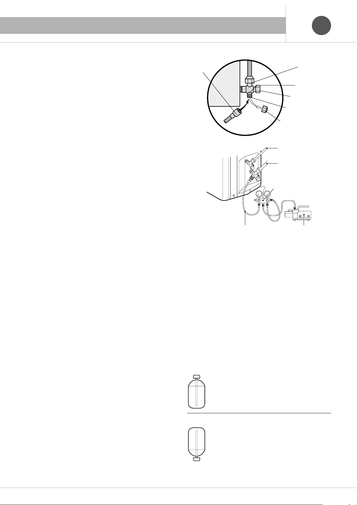
1. DESCRIZIONE DEI COMPONENTI
7. LOAD AND SYSTEM TEST
GBGB
ITIT
7.1 Draining and filling
the refrigerating circuit with R 410 A
- The operations indicated below must be carried out only after disconnecting the air conditioner from the power supply.
- The outdoor unit holds a refrigerant R410A charge suitable for pipelines
up to 5 meters in length.
- Do not mix any substance other than the specified refrigerant (R41 OA)
into the refrigeration cycle.
- When refrigerant gas leaks occur, ventilate the room as soon and as
much as possible.
- R410A, as well as other refrigerants, should always be recovered and
never be released directly into the environment.
- Use a vacuum pump for R41 OA exclusively. Using the same vacuum
pump for different refrigerents may damage the vacuun pump or the unit.
- Use tools (manifold, hoses and vacuum pump) dedicated exclusively to
systems using R-410A refrigerant.
-
Do not substitute or mix one gas with another, as they are not compatible.
- For an R 410 A charge, it is imperative to introduce the refrigerant in
liquid phase.
7.1.1 Procedura di vuoto e carica
- Tighten the unions (Fig. A) as indicated at page6.3.4.
- Connect a vacuum pump to the service connection 3 (fig. A), via a set
of portable pressure gauges.
- Keep it running until a vacuum of 1 mBar or below has been reached, if
the pump is fitted with a vacuum gauge, or for at least 15 minutes if a
vacuum gauge is not available..
- Close the valve on the set of gauges connected to the pump, and turn
the pump off.
- If the pressure gauge set is fitted with a vacuum gauge, wait at
least 5 minutes, then check that the vacuum in the system has been
maintained. If not, look for the cause of the leak.
- For pipelines longer than 5 meters, it is necessary to fill the circuit, using
a measuring cylinder or an electronic balance, with a quantity of R 410A
liquid phase proportional to the size and length of the pipes used, as
shown in the following table page 35.
Note:
To determine the charge additional Considering the length of a single
line.
Flexible hose
connector
Service connection 3
Service connection cap
Fig. A
Liquid
MIC55
Flexible line
After the addition of any refrigerant gas charge which may be necessary:
- Remove caps B (Fig. A) and with the appropriate key open the valves (it
is good practice to open them all the way, then close them by a half of a
turn).
- Put caps B (Fig. A) back on and tighten them.
- Check for possible leaks at the unions with a refrigerant gas leak
detector.
- Disconnect the equipment used from the union 3 (fig A) and close the
service connectors, refitting their caps tightly.
7.1.2 Precautions when adding refrigerant
- Fill from the liquid pipe in liquid form.
- Precautions when adding R410A. It is a mixed refrigerant, so adding
it in gas form may cause the refrigerant composition to change,
preventing normal operation.
-
Before filling, check whether the cylinder has a siphon attached or not.
(lt should have something like “liquid filling siphon attached” displayed on
it.)
Gas
Gauge group
Vacuum pump
Union
3-way valve
Valve cap 2
42
Filling a cylinder with an attached siphon
Stand the cylinder upright when filling.
There is a siphon pipe inside, so the cylinder need not
be upside-down to fill with liquid.
Filling other cylinders
Turn the cylinder upside-down when filing .
Check the type of refrigerant to be used on the machine namiplate.

1. DESCRIZIONE DEI COMPONENTI
7. LOAD AND SYSTEM TEST
GBGB
ITIT
7.2 Test running
(the first start-up absolutely must occur in
Cooling mode)
Before starting the test, make sure you have correctly completed
the following work:
- Pipe;
- Connection of electrical cables;
- Correspondence correct the indoor and outdoor;
- Filling appropriate coolant, if necessary;
- Ensure that all stop valves are fully open;
- Check that the voltage supplied to the outdoor unit and the indoor units is 230V.
- To test cooling, set the lowest temperature at 16 °C.
- To test heating, set the highest temperature, at 30 °C.
- Please check both cooling and heating operation of each unit
individually and then also check the simultaneous operation of
all indoor units.
- After running the unit for about 20 minutes, check the indoor
unit outlet temperature.
Note:
If room temperature is lower than 16°C it will be impossible to
test the operation in Cooling mode with the remote control, as
well as if room temperature is higher than 30°C it will be impossible to test the operation in Heating mode.
7.3 Refrigerant Recovery
Refrigerant should always be recovered in special tanks by using
the recovery unit and following its using instructions.
Note:
Refrigerant should never be released into the atmosphere as specified
in Regulation (EC) no. 2037/2000 of the European Parliament and of the
Council.
Note:
When unit stops or operating mode has been changed, the compressor does not start working before 3 min.
When operating in Cooling mode, some frost may form on the
Indoor unit or on piping.
Please let the unit work according to the relevant manual instructions. Explain to the final user the air conditioner functioning
through the observance of the instructions manual.
Items to confirm:
Gas leakage from pipe connection?
Heat insulation treatment of pipe connection?
Are the connection wiring of indoor and outdoor unit firmly
inserted into the terminal block?
Is the connection wiring of indoor and outdoor firmly fixed?
Is drainage securely arranged?
Is the ground wire securely and firmly connected?
Is power supply voltage abided by electric code?
Is there any noise?
Does cooling perform normally?
Does room temperature regulator operate normally?
43

1. DESCRIZIONE DEI COMPONENTI
8. DISPOSAL
8.1 Enviromental safeguard information!
This equipment contains fluorinated greehouse gases covered
by Kyoto Protocol. It should only be serviced or dismantled by
professional trained personnel.
Directive 2012/19/EC (WEEE): Information for users
This product complies with EU Directive 2012/19/EC.
The barred bin symbol on the appliance indicates that the product, requiring separate treatment to household waste after its normal working
life, must be taken to a waste-sorting centre for electrical and electronic
appliances or returned to the retailer at the time of purchasing a new
equivalent appliance.
The user is responsible for taking the appliance to the appropriate waste
collection centre at the end of its working life.
Correct waste sorting, with the discarded appliance being sent for
recycling, treatment and compatible environmental disposal helps
prevent any negative effects on the environment and health, and encourages the recycling of product materials.
For further detailed information regarding available collection systems,
please contact your local waste disposal service or the shop where you
made your purchase.
GBGB
ITIT
8.3
Disposal rules for the new air conditioner
packaging
All of the air conditioner packing materials can be disposed of without
harming the environment. The cardboard box must be cut into pieces and
delivered to a paper collection container. The plastic and polystyrene
packaging does not contain fluorine or hydrocarbons.
All of these materials can be deposited in a waste dump and recycled
after proper treatment. Contact your local authorities for information on
waste disposal.
9.4 Battery disposal
The batteries have been designed and produced with
high quality materials and the components can be
recycled and/or re-used.
The symbol of the crossed-out rubbish bin indicates that
the product (batteries) at the end of its useful life must
be handled separately from domestic waste and must be
sent to a separate waste collection center, as provided by the European
Community 2006/66EC, art. 20 and annex II.
If under the bin there is a chemical symbol, this indicates that the batteries have a certain concentration of heavy metal.and it will be indicated
as follows:
Hg: mercury (0,0005%), Cd: cadmium (0,002%), Pb: lead (0,004%)
8.2 Disposal rules for the old air conditioner
Before disposing of your old air conditioner, make sure that it is off and
unplug it. The refrigerant it contains requires a special procedure for disposal. Materials of value in the air conditioner can be recycled. Contact
local authorities or the waste disposal facility for more information.
Make sure you do not damage the pipes of the air conditioner before you
take it to the waste disposal facility. Help protect the environment by
following a correct, non-polluting method of disposal.
44

1. DESCRIZIONE DEI COMPONENTI
9. MALFUNCTION
Under particular conditions the air conditioner can have operation malfunctions which often are apparent or determined by accidental causes
or, most of the time, by trivial ones.
Warning!
Before requesting the service centre to intervene, it is recommended to
have simple checks in order to continuously make the best use of the air
conditioner performance as well as to avoid useless service interventions.
ITIT
Defect
The air conditioner does not start.
The remote control display dims when a command is sent.
Doesn’t the air conditioner indicate reception of the signal sent by the remote
control with a “beep”?
In winter use is the starting of the internal ventilation delayed of a few minutes or does it suddenly stop and restart after some time?
In winter use the external fan turns for a couple of minutes even if the air
conditioner has been turned off.
Does the air conditioner not cool sufficiently?
Does the indoor unit of the air conditioner have surfaces with condensation,
especially near the cold air outlet?
Does the air conditioner not heat sufficiently?
Possible cause
- Is the air conditioner electrically supplied?
- Are there any wrong operation settings on the remote control?
- Is anything stopping the reception of the infrared signal on the air conditioner? (a beep must be heard).
- Are the batteries in the remote control correctly inserted?
- Are the remote control batteries flat?
- It is a normal situation since the air conditioner is equipped with a thermal
sensor inserted in the coil of the indoor unit which optimizes the operation
of the fan till a temperature of 38 °C is reached.
- It is a normal situation since the air conditioner disposes all the heat present in the exchanger.
- Are the indoor unit air filters dirty or clogged?
- Is the outdoor unit grid clogged?
- Is there an open window?
- Is the temperature on the remote control set regularly?
- If the room is very humid this phenomenon is considered normal.
- If the room is not excessively humid check the correct direction of the air
flowing out of the air conditioner.
- Open windows.
- Are the indoor unit air filters dirty or clogged?
- Is the outdoor unit grid very clogged?
- Is the temperature set on the remote control correct?
- If the indoor unit is installed very high, due to the hot air stratification phenomenon, it is recommended to set the temperature on the remote control
with an increase of 4/5 °.
- During heat pump operation, frost accumulates on the surface of the outdoor unit which reduces the efficiency of the air conditioner.
Such frost is melted and removed with the “defrosting” operation entirely
managed by a microprocessor.
With severe outdoor temperatures (-8 °C) or high humidity (90% U.R.), the
defrosting cycles will be more frequent and in such case it will be necessary to resort to another source of additional heat.
If the air conditioners emits strong odours?
The air conditioner is noisy?
- Have the filters been cleaned?
- Has ordinary maintenance been carried out?
- When the air conditioner starts to cool or stops during heating, it is possible to hear noises such as rustlings or gurglings due to the cooling liquid’s
circulation inside the conditioner;
- Upon the air conditioner’s starting or turning off, creaks may be heard due
to dilatation.
45
1. DESCRIZIONE DEI COMPONENTI
9. MALFUNCTION
N° Type of anomaly Display Possible causes
1. Too much coolant.
1 High pressure protection E1
2 indoor unit ice protection E2
3 Low pressure protection E3
Compressor discharge high temperature
4
protection
5 Overload protection E5
2. Poor heat exchange (exchanger dirty or poor air circulation).
3. Ambient temperature too high.
1. Poor heat exchange (exchanger dirty or poor air circulation).
2. indoor unit fan motor damaged.
1. Not enough coolant;
2. Loss of coolant.
1. Too much coolant.
E4
2. Ambient temperature too high.
3. Poor heat exchange (exchanger dirty or poor air circulation).
1. Supply voltage unstable.
2. Supply voltage low.
3. Too much coolant.
4. Ambient temperature too high.
5. Poor heat exchange (exchanger dirty or poor air circulation).
GBGB
ITIT
6 Communication error E6
7 Operating mode in conflict E7
8 Capacitor coil overheating protection E8
9 EEPROM anomaly EE Outdoor unit AP1 electronic board damaged.
10
11
12 Bridge anomaly C5 The bridge on the electronic board of the indoor unit is not inserted correctly.
13 Coolant recovery F0 The outdoor unit has received the signal to start the "Coolant recovery"
14
15
16
17
18
19
Reduced frequency for overcurrent of the
IPM module
Reduced frequency for overtemperature
of the IPM module
Indoor unit ambient temperature sensor
anomaly
Indoor unit evaporator temperature
sensor anomaly
Outdoor unit ambient temperature sensor
anomaly
Outdoor unit capacitor temperature
sensor anomaly
Outdoor unit discharge temperature
sensor anomaly
Reduced frequency for overheating of the
condensing coil
1. Communication cable between indoor and outdoor units not connected correctly.
2. Control wire not connected correctly (if installed).
The operating mode of the indoor unit is in conflict with the operation of the outdoor
unit.
1. Too much coolant;
2. Poor heat exchange (exchanger dirty or poor air circulation);
3. Ambient temperature too high.
1. Check the thermal insulation of the IPM module and the radiator (the unit must be
En
off for at least 20 minutes);
2. Outdoor unit electronic board damaged.
1. Check the thermal insulation of the IPM module and the radiator (the unit must be
EU
F1
F2
F3
F4
F5
F6
off for at least 20 minutes);
2.
2. Outdoor unit AP1 electronic board damaged.
1. Loosening or bad contact of the temperature sensor with the electronic board.
2. Temperature sensor damaged.
3. Indoor unit electronic board damaged.
1. Loosening or bad contact of the temperature sensor with the electronic board.
2. Temperature sensor damaged.
3. Indoor unit electronic board damaged.
4. The temperature sensor head has not been inserted inside the copper pipe.
1. Loosening or bad contact of the temperature sensor with the electronic board.
2. Temperature sensor damaged.
3. Outdoor unit electronic board damaged.
1. Loosening or bad contact of the temperature sensor with the electronic board.
2. Temperature sensor damaged.
3. Outdoor unit electronic board damaged.
4. The temperature sensor head has not been inserted inside the copper pipe.
Loosening or bad contact of the temperature sensor with the electronic board.
1.
2. Temperature sensor damaged.
3. Outdoor unit electronic board damaged.
4.
The temperature sensor head has not been inserted inside the copper pipe.
1. Supply voltage low.
2. Too much coolant.
3. Ambient temperature too high.
4. Poor heat exchange (exchanger dirty or poor air circulation).
46

1. DESCRIZIONE DEI COMPONENTI
9. MALFUNCTION
N° Type of anomaly Display Possible causes
1. Supply voltage low.
20 Reduced frequency for overcurrent F8
Reduced frequency for overtemperature
21
of exhaust air.
Reduced frequency for indoor unit ice
22
protection
23 Voltage too high for the electronic board PH
24 Voltage too low for the electronic board PL
25 Fixed frequency test P0 Displayed during the P0 fixed frequency test.
26 Fixed frequency test P1 Displayed during the P1 fixed frequency test.
27 Fixed frequency test P2 Displayed during the P2 fixed frequency test.
28 Fixed frequency test P3 Displayed during the P3 fixed frequency test.
29 Fixed frequency test P4 Displayed during the P4 fixed frequency test.
30 Fixed frequency test P5 Displayed during the P5 fixed frequency test.
31 Fixed frequency test P6 Displayed during the P6 fixed frequency test.
32 Fixed frequency test P7 Displayed during the P7 fixed frequency test.
33 IPM module high temperature protection P8
34 Capacitor charging anomaly PU
35 Defrosting H1 Normal operation during the heating mode.
36 Ionizer protection H2
37 Compressor overload protection H3
38 Anomaly in the system H4
39 IPM module protection H5
2. Too much coolant.
3. Ambient temperature too high.
4. Poor heat exchange (exchanger dirty or poor air circulation).
1. Ambient temperature too high;
F9
2. Not enough coolant;
3. Malfunction of the electronic expansion valve.
1. Poor heat exchange (exchanger dirty or poor air circulation).
FH
2. Indoor unit fan speed too low;
1. Voltage between L and N on the terminal board over 265 VAC;
2. Wiring loose (the unit must be off for at least 20 minutes before checking the
wiring);
3. Electronic board damaged.
1. Voltage between L and N on the terminal board below 150 VAC;
2. Wiring loose (the unit must be off for at least 20 minutes before checking the
wiring);
3. Electronic board damaged.
1. Check the thermal insulation of the IPM module and the radiator (the unit must be
off for at least 20 minutes);
2.
2. Outdoor unit AP1 electronic board damaged.
1. Voltage between L and N on the terminal board different from 210 ÷ 250 VAC
2. Wiring loose or cut (the unit must be off for at least 20 minutes before checking the
wiring);
3. Capacitor damaged
4. Outdoor unit AP1 electronic board damaged.
1. Ionizer wiring loose or cut;
2. Ionizer damaged;
3. Indoor unit electronic board damaged.
1. Compressor wiring loose or cut (in normal operating conditions the resistance for
this terminal should be less than 1 ohm);
2. Too much or not enough coolant.
3. Obstruction in the cooling circuit;
4. Malfunction of the compressor.
1. Condensing temperature too high;
2. Ambient temperature too high;
3. Poor heat exchange (exchanger dirty or poor air circulation).
1. Voltage between L and N on the terminal board different from 210 ÷ 250 VAC;
2. Compressor wiring loose or cut;
3. Compressor damaged;
4. Too much or not enough coolant;
5. High load or insufficient heat transfer.
GBGB
ITIT
47

1. DESCRIZIONE DEI COMPONENTI
9. MALFUNCTION
N° Type of anomaly Display Possible causes
1. Motor wiring loose or cut;
40 Malfunction of the indoor unit fan motor H6
41 Desynchronization of the compressor H7
42 Power factor anomaly HC
43
44 High absorption power protection L9 Power absorbed high
45 Indoor unit and outdoor unit not coupled LP Indoor unit and outdoor unit not coupled
46 No start LC
47
48
49
50 Malfunction of four-way valve U7
51 Outdoor unit zerocrossing anomaly U8
52
53
Malfunction of the outdoor unit fan
motor
Phase current anomaly detected in the
compressor circuit
Anomaly for voltage drop for the DC
bus-bar
Anomaly in the detection of current for
the entire unit
Malfunction of the coolant (liquid)
temperature sensor
Malfunction of the coolant (gas) temperature sensor
2. Motor blocked;
3. Motor damaged;
4. Indoor unit electronic board damaged.
1. Voltage between L and N on the terminal board different from 210 ÷ 250 VAC;
2. Compressor wiring loose or cut;
3. Compressor damaged;
4. Too much or not enough coolant;
5. Poor heat exchange (exchanger dirty or poor air circulation).
1. Voltage between L and N on the terminal board different from 210 ÷ 250 VAC;
2. Wiring loose or cut (the unit must be off for at least 20 minutes before checking the
wiring);
3. Outdoor unit AP1 electronic board damaged.
1. Motor wiring loose or cut;
2. Motor blocked;
L3
3. Motor damaged;
4. Outdoor unit electronic board damaged.
1. Time required by the compressor;
2. Compressor wiring loose or cut;
3. Compressor damaged;
1. Voltage between L and N on the terminal board different from 210 ÷ 250 VAC;
2. Compressor wiring loose or cut;
U1
3. Compressor damaged;
4. Outdoor unit AP1 electronic board damaged.
1. Unstable voltage between L and N on the terminal board;
U3
2. Outdoor unit AP1 electronic board damaged.
U5
Outdoor unit AP1 electronic board damaged.
1. Supply voltage below 175 VAC;
2. Four-way valve wiring loose or cut;
3. Four-way valve damaged.
4. Outdoor unit AP1 electronic board damaged.
1. Motor wiring loose or cut;
2. Indoor unit electronic board damaged.
1. Loosening or bad contact of the temperature sensor with the electronic board.
2. Temperature sensor damaged.
b5
3. Outdoor unit AP1 electronic board damaged.
4. The temperature sensor head has not been inserted inside the copper pipe.
1. Loosening or bad contact of the temperature sensor with the electronic board.
2. Temperature sensor damaged.
b7
3. Outdoor unit AP1 electronic board damaged.
4. The temperature sensor head has not been inserted inside the copper pipe.
GBGB
ITIT
48

1. DESCRIZIONE DEI COMPONENTI
SCHEDA PRODOTTO / PRODUCT FICHE
ITIT
GBGB
Fontanafredda (Pn) - Italy
Fontanafredda (Pn) - Italy
49

1. DESCRIZIONE DEI COMPONENTI
SCHEDA PRODOTTO / PRODUCT FICHE
ITIT
GBGB
Fontanafredda (Pn) - Italy
Fontanafredda (Pn) - Italy
50

1. DESCRIZIONE DEI COMPONENTI
11. SCHEDA PRODOTTO / PRODUCT FICHE
ITIT
GBGB
Fontanafredda (Pn) - Italy
Fontanafredda (Pn) - Italy
51

1. DESCRIZIONE DEI COMPONENTI
SCHEDA PRODOTTO / PRODUCT FICHE
ITIT
GBGB
Fontanafredda (Pn) - Italy
DE
Fontanafredda (Pn) - Italy
QE
52

53

1. DESCRIZIONE DEI COMPONENTI
SCHEMI ELETTRICI - ELECTRIC SCHEMES SCHEMI ELETTRICI - ELECTRIC SCHEMES
ITIT
GBGB
XECO 0915E, XECO 1215E (vedi leggenda a p. 58 - see legend p. 58)
3OHDVHGRQWWRXFKDQ\
WHUPLQDOZKHQWKHPDFKLQHLV
UXQQLQJVWRSSLQJRUKDVEHHQ
SRZHUHGRIIIRUOHVVWKDQ
PLQXWHVWRSUHYHQWWKHULVN
RIHOHFWULFVKRFN
%8
%.
%1
<(*1
:$51,1*
;7
1
1
/
<(*1
0$*1(7,&
5,1*
/
/
,1'22581,7
7(50,1$/
%/2&.
%8
1
%1
/
<(*1
(/(&75,&$/
3(
%2;
<(*1
3(
32:(5
0,',62/$7,21
6+((7
BU
BK
BN
N
/
<(*1
/
5,1*
0$*1(7,&
<(*1
28778%(
7(03
6(1625
©
57
1
&208
$&/
3(
8
%8
<(
<(
%8
8
&203
3(
&203
2875220
7(03
6(1625
©
57
N
:
9
5'
5'
9
(;+$867
©
57
N
&1
29&&203
;
5'
6$7
:
29(5/2$5'
3527(&725
7(03
6(1625
(/(&7521,&
(;3$16,21
9$/9(
(.9
&1
:$<
9$/9(
<9
97
:$<
$30DLQ%RDUG
2)$1
5'
<(*1
0
3(
)$1
3(
02725
127(
0RWRU
JURXQGRQO\
DSSOLHVWRWKH
LURQVKHOOPRWRU
97
(+
&RPS
%DQG
+HDWHU
5($&725
%8
/
5,1*
0$*1(7,&
/;
/
/;
+($7+($7
(+
%RWWRP
%DQG
+HDWHU
%1
/
XECO 1815E, XECO 2415E (vedi leggenda a p. 58 - see legend p. 58)
:$51,1*
3OHDVHGRQWWRXFKDQ\WHUPLQDO
ZKHQWKHYROWDJHRIWHUPLQDO
3'&DQG1'&DW$3LV
KLJKHUWKDQ9WRSUHYHQWWKH
ULVNRIHOHFWULFVKRFN
<(*1
7(50,1$/
3(
%/2&.
%8
1
%.
%1
,1'22581,7
%1
%8
/
1
;7
<(*1
32:(5
1
/
%8
%1
0$*1(7,&
5,1*
3(
/
/
/
%.
&20B,11(5
%1
$&B/
%8
1
<(*1
/
28778%(
57 57 57
©
:+
3(
3(
29(5/2$'3527(&725
:+:+
7(036(1625
2875220
7(036(1625
(;+$867
7(036(1625
0$*1(7,&
5,1*
©
©
...
%.
7B6(1625
29&B&203
$3
35,17('&,5&8,7%2$5'
+($7B%
5'
(+
%27720
%$1'
+($7(5
5'
:$< 2)$1
9797
<9
:$<
9$/9(
6$7
&203
/
/
<(
%8
<(%8
0
)$102725
&203
/
5'
5'
:5'9<(8%8
3(
3(
:98
3(
;
<(*1
3(
<(*1
54

1. DESCRIZIONE DEI COMPONENTI
9. SCHEMI ELETTRICI
SCHEMI ELETTRICI - ELECTRIC SCHEMES
XECO 1415DE (vedi leggenda a p. 58 - see legend p. 58)
ITIT
GBGB
7(50,1$/
/
1
32:(5
,1'22581,7$
,1'22581,7%
/
1
32:(5
%1%.
%8
<(*1
%8
%.
%1
<(*1
3(
%8
%.
%1
<(*1
3(
'5('
02'8/(
%/2&.
;7
7(50,1$/
%/2&.
1
;7$
7(50,1$/
%/2&.
1
;7%
/%1/
/
1
5-&211(&725
/
<(*1
3(
%8
%8
%1
/
:$51,1*
3OHDVHGRQWWRXFKDQ\WHUPLQDO
ZKHQWKHYROWDJHRIWHUPLQDO
3'&DQG1'&DW$3LV
KLJKHUWKDQ9WRSUHYHQWWKH
ULVNRIHOHFWULFDOVKRFN
%8
/
<(*1
3(
%1
&2035(6625
%$1'+($7(5
'5('
$&/
1
(3(
$3)LOWHU%RDUG
/
%.
/
*<
(/(&7521,&
(;3$16,21 (;3$16,21
9$/9($
(.9
(+
:+ %.
5'5'
+($7&
)$ )%
$30DLQ%RDUG
2)$1
0
<(*1
)$102725
3(
%8
%1
%8
1
$&/
76(1625
1
&20,11(5
29&&203
%.
5'%.
©
*$69$/9( /,48,'9$/9(
7(036(1625 7(036(1625
1
$&/
1
(/(&7521,&
9$/9(%
(.9
78%($
:+
©
57 57
4$ <$ 4% <%
*$69$/9(
7(036(1625
/,48,'9$/9(
7(036(1625
:$<
78%(%
©
8%8
9<(
:5'
©
%.
:+
%8
<(
5'
&211(&725
:+
:+
5'%.
5757
57
.
©
57
.
©
57
.
©
97
<9
97
/
/
/
6$7
29(5/2$'
3527(&725
287'22581,7
(;+$867
7(036(1625
2875220
7(036(1625
28778%(
7(036(1625
:$<9$/9(
%8
<(
5'
:;98
&203
&203
<(*1
3(
3(
XECO 1815DE (vedi leggenda a p. 58 - see legend p. 58)
7(50,1$/
%/2&.
%1%.
/
1
<(*1
32:(5
,1'22581,7$
,1'22581,7%
/
%8
1
;7
7(50,1$/
%/2&.
%8
1
%.
%1
<(*1
;7$
3(
7(50,1$/
%/2&.
%8
1
%.
%1
<(*1
;7%
3(
%27720
%$1'+($7(5
:$51,1*
3OHDVHGRQWWRXFKDQ\WHUPLQDO
ZKHQWKHYROWDJHRIWHUPLQDO
3'&DQG1'&DW$3LV
KLJKHUWKDQ9WRSUHYHQWWKH
ULVNRIHOHFWULFDOVKRFN
/
/
<(*1
3(
%8
%8
%1
(+
/
/
%1
5'
5'
%1
$&/
%8
1
/
(3(
<(*1
$3)LOWHU%RDUG
3(
&2035(6625
%$1'+($7(5
+($7&
+($7%
<(*1
3(
%.
*<
(/(&7521,&
9$/9($
(+
5'
2)$1
0
)$102725
%8
1
%1
$&/
%8
1
/
/
(/(&7521,&
(;3$16,21(;3$16,21
9$/9(%
(.9
(.9
%.:+
)%)$
$30DLQ%RDUG
78%($
:+
%. 5'
©
*$69$/9(
7(036(1625
/,48,'9$/9(
7(036(1625
©
5757
1
$&/
1
&20,11(5
%.
76(1625
:$<
8%8
9<(
:5'
29&&203
78%(%
%. 5'
©
57 57
<%4%<$4$
/,48,'9$/9(*$69$/9(
7(036(16257(036(1625
%.
:+
%8
<(
5'
&211(&725
:+
:+
©
57
.
©
57
.
©
.
57
©
97
<9
97
/
/
/
6$7
29(5/2$'
3527(&725
287'22581,7
(;+$867
7(036(1625
2875220
7(036(1625
28778%(
7(036(1625
:$<9$/9(
%8
<(
5'
89;:
&203
&203
<(*1
3(
3(
55

1. DESCRIZIONE DEI COMPONENTI9. SCHEMI ELETTRICI
SCHEMI ELETTRICI - ELECTRIC SCHEMES
XECO 2415TE (vedi leggenda a p. 58 - see legend p. 58)
ITIT
GBGB
7(50,1$/
32:(5
/
1
,1'22581,7$,1'22581,7%,1'22581,7&
%/2&.
%1%.
/
%8
1
<(*1
;7
3(
;7$
%8
1
%.
%1
<(*1
7(50,1$/
3(
%/2&.
;7%
%8
1
%.
%1
<(*1
7(50,1$/
3(
%/2&.
;7&
%8
1
%.
%1
<(*1
7(50,1$/
%/2&.
3(
&2035(6625
%$1'+($7(5
3OHDVHGRQWWRXFKDQ\WHUPLQDOZKHQ
WKHYROWDJHRIWHUPLQDO3'&DQG
1'&DW$3LVKLJKHUWKDQ9WR
SUHYHQWWKHULVNRIHOHFWULFDOVKRFN
%1
%8
%8 %1
%8 %1
:$51,1*
57
.
+33
8%8
9<(
:5'
5'
5'
5'%.
©
/LTXLG9DOYH
7HPS6HQVRU
%.
.
.
:+
<(
%8
97
97
;
%8
<(
5'
&211(&725
:+
:+
29(5/2$'
3527(&725
(;+$867
©
7(036(1625
57
2875220
©
7(036(1625
57
28778%(
©
7(036(1625
+,*+
35(6685(
3
+36
6:,7&+
<9
/
%8
/
<(
/
5'
6$7
&203
&203
0
)$102725
%27720
+($7(5
(+
287'22581,7
:$<
9$/9(
%$1'
89:
<(*1
3(
3(
3(
<(*1
3(
/
/
%1
/
%8
5'
5'
/
$&/
/
1
<(*1
(
$3)LOWHU%RDUG
3(
(/(&7521,&
9$/9($
:+
(;3$16,21(;3$16,21
9$/9(%
(.9
+($7&
:+
*DV9DOYH
7HPS6HQVRU 7HPS6HQVRU
(/(&7521,&(/(&7521,&
(;3$16,21
9$/9(&
(.9
5'%.
)%)$
78%($
%. 5'
©
<$4$
/LTXLG9DOYH
7HPS6HQVRU
%.
*<
:+
%8
(.9
)&
©
5757
$&/
/
/
/
/
5($&725
/ /
$30DLQ%RDUG
%.
4% <%
*DV9DOYH *DV9DOYH
/
%1
/
%8
1
<(*1
(
3(
/
%8
/
/
2*:+
/;/;
78%(%
5'%.
©
57 57
©
/LTXLG9DOYH
7HPS6HQVRU 7HPS6HQVRU
$&/
1
76(1625
&20,11(5
1
/;
/;
29&&203
78%(&
5'
©
57 57
4& <&
:$<
2)$1
+($7%
XECO 2815QE (vedi leggenda a p. 58 - see legend p. 58)
32:(5
/
1
7(50,1$/
%/2&.
%1%.
/
%8
1
<(*1
;7
3(
7(50,1$/%/2&.
%8
1
%.
%1
<(*1
;7$
3(
7(50,1$/%/2&.
%8
1
%.
%1
<(*1
3(
7(50,1$/%/2&.
%8
%.
%1
<(*1
3(
7(50,1$/%/2&.
%8
%.
%1
<(*1
3(
;7%
1
;7&
1
;7'
,1'22581,7% ,1'22581,7$
,1'22581,7&
,1'22581,7'
3OHDVHGRQWWRXFKDQ\WHUPLQDOZKHQ
WKHYROWDJHRIWHUPLQDO3'&DQG
1'&DW$3LVKLJKHUWKDQ9WR
SUHYHQWWKHULVNRIHOHFWULFDOVKRFN
%1
%8
%1
%8
%1%8
%1%8
%8 %1
:$51,1*
/
/
/
(/(&7521,&
(;3$16,21
9$/9(A
:+ %. 5'
(/(&7521,& (/(&7521,&
(;3$16,21
9$/9(%
(.9
)$
:+
4$ <&4&<%4%<$
*DV
9DOYH
7HPS
6HQVRU
(.9
)%
78%($ 78%('
©
©
57
9DOYH
7HPS
6HQVRU
/
/
<(*1
3(
(;3$16,21
9$/9(&
78%(%
*DV /LTXLG/LTXLG
7HPS
6HQVRU
%.
*<
:+
5'
%8
(.9
%. 5'5'%.
©
$&/
1
(
$30DLQ%RDUG
/
/
/
/
/
(/(&7521,&
(;3$16,21
9$/9('
(.9
<(
)&
5'%.
©
575757
9DOYH9DOYH
7HPS
6HQVRU
)'
*DV
9DOYH
7HPS
6HQVRU
78%(&
$&/
:+ 2*
57 57
%1
%8
1
<(*1
(
3(
%8
5($&725
/
/
/; /;
5'%.
©
©
/LTXLG
9DOYH
7HPS
6HQVRU
/
/
/
/
/
<(
4' <'
*DV
9DOYH
7HPS
6HQVRU
$&/
76(1625
1
+33
:$<
&20,11(5
1
29&&203
/;
/;
+($7&
2)$1
$30DLQ%RDUG
+($7%
©
5757
/LTXLG
9DOYH
7HPS
6HQVRU
5'
%27720
%$1'
+($7(5
%. 5'
©
8%8
9<(
:5'
5'
(+
%.
57
57
:+
57
<(
%8
97
97
:+
:+
;
%8
<(
5'
&211(&725
5'
5'
(;+$867
©
.
7(036(1625
2875220
©
.
7(036(1625
28778%(
©
.
7(036(1625
+,*+
35(6685(
3
+36
/
/
/
6:,7&+
<9
6$7
%8
8
<(
&203
9
5'
:
&203
&2035(6625
%$1'+($7(5
0
)$102725
287'22581,7
:$<
9$/9(
29(5/2$'
3527(&725
3(
<(*1
3(
<(*1
3(
3(
56

1. DESCRIZIONE DEI COMPONENTI9. SCHEMI ELETTRICI
SCHEMI ELETTRICI - ELECTRIC SCHEMES
XECO 4216CE (vedi leggenda a p. 58 - see legend p. 58)
ITIT
GBGB
57

1. DESCRIZIONE DEI COMPONENTISCHEMI ELETTRICI - ELECTRIC SCHEMES
ITIT
GBGB
Leggenda - IT Legend - GB
Morsettiera della unità interna XT TERMINAL BLOCK
Filo colore blu BU
Filo colore nero BK
Filo colore marrone BN
Filo colore rosso RD
Filo colore bianco WH
Filo colore grigio GY
Filo colore giallo YE
Filo colore giallo/verde YEGN
Scheda elettronica principale AP1
Scheda elettronica filtro AP2
Compressore COMP
Unità interna INDOOR UNIT
Induttanza toroidale MAGNETIC RING
Induttanza REACTOR
Induttanza L
Riscaldatore elettrico per compressore EH COMP. BAND HEATER
Riscaldatore elettrico per compressore EH1 COMP. BAND HEATER
Riscaldatore elettrico basamento unità
esterna
Valvola 4 vie 4YV 4 WAY VALVE
Valvola espansione elettronica EKV ELECTRONIC EXPANSION VALVE
Sensore temperatura GAS
Sensore temperatura esterna RT2 OUTROOM TEMP SENSOR
Sensore temperatura scambiatore unità
esterna
Protezionecompressore SAT OVERLOAD PROTECTOR
Pressostato di alta ( AP) HPS HIGH PRESSURE SWITCH
Pressostato di alta 1 (YKB-4.2/3.6-C) HP1
Pressostato di alta 2 (YKB-3.7/3.1-C) HP2
Pressostato di bassa LP
Motore ventilatore M / M1 FAN MOTOR
Alimentazione elettrica 230V~ 50Hz POWER
Sensore temperatura GAS unità A QA GAS VALVE TEMP SENSOR
Sensore temperatura GAS unità A RT6 GAS VALVE TEMP SENSOR
Sensore temperatura GAS unità B QB GAS VALVE TEMP SENSOR
Sensore temperatura GAS unità B RT8 GAS VALVE TEMP SENSOR
Sensore temperatura GAS unità C QC GAS VALVE TEMP SENSOR
Sensore temperatura GAS unità C RT10 GAS VALVE TEMP SENSOR
Sensore temperatura GAS unità D QD GAS VALVE TEMP SENSOR
Sensore temperatura GAS unità D RT12 GAS VALVE TEMP SENSOR
Sensore temperatura GAS unità E RT14 GAS VALVE TEMP SENSOR
EH2 BOTTOM BAND HEATER
RT3 EXHAUST TEMP SENSOR / DIS
CHARGE GAS TEMP SENSOR
RT1 OUTTUBE TEMP SENSOR
Leggenda - IT Legend - GB
Sensore temperatura LIQUIDO unità A YA LIQUID VALVE TEMP SENSOR
Sensore temperatura LIQUIDO unità A RT7 LIQUID VALVE TEMP SENSOR
Sensore temperatura LIQUIDO unità B YB LIQUID VALVE TEMP SENSOR
Sensore temperatura LIQUIDO unità B RT9 LIQUID VALVE TEMP SENSOR
Sensore temperatura LIQUIDO unità C YC LIQUID VALVE TEMP SENSOR
Sensore temperatura LIQUIDO unità C RT11 LIQUID VALVE TEMP SENSOR
Sensore temperatura LIQUIDO unità D YD LIQUID VALVE TEMP SENSOR
Sensore temperatura LIQUIDO unità D RT13 LIQUID VALVE TEMP SENSOR
Sensore temperatura LIQUIDO unità E RT15 LIQUID VALVE TEMP SENSOR
ATTENZIONE WARNING
Per evitare il rischio di scosse elettriche
-
e lesioni, non toccare i terminali e/o com
ponenti elettrici ed elettronici quando
l’unità è in funzione, ferma o spenta ed
attendere almeno 30 minuti dopo aver
tolto alimentazione elettrica alla unità.
ATTENZIONE WARNING
Per evitare il rischio di scosse elettriche
e lesioni, non toccare i terminali e/o com
ponenti elettrici ed elettronici , quando la
tensione al terminale P (DC +) e N (DC-)
sulla scheda elettronica AP1 è superiore
a 30V.
-
AVVISO: NOTICE:
Nessuno strippaggio riscaldatore di
fascia compressore non ha bisogno di
morsetti di cablaggio di collegamento;
Linea Noumero W23 e Numero. Linea
W24 sono sostituiti da due fili di piomboout dotati di riscaldamento di banda, col
legati alla AP HEAT.
Please don’t touch any terminal when the
machine is running, stopping or has been
powered off for less than 30 minutes to
prevent the risk of electric shock!
-
Please don’t touch any terminal when the
voltage of terminal P (DC+) and N (DC-) at
AP1 is higher than 30V to prevent the risk
of electric shock!
None stripping compressor band heater
doesn’t need the connection wiring terminals; No W23 line and N0. W24 line
are replaced by the two lead-out wires
equipped with band heater, connected to
the AP HEAT.
58

1. DESCRIZIONE DEI COMPONENTIREFRIGERANT CIRCUITS / CIRCUITI FRIGO
outdoor
indoor
D1
C
1
B
1
A
1
filter
A heat exchanger
gas -liquid separator
inverter compressor
discharge silencer
discharge temperature
sensor
SP
4-way valve
outdoor heat exchanger
fan
high pressure switch
B heat exchanger
C heat exchanger
D heat exchanger
filter
filter
filter
filter
C2
C3
D3
D2
B3
B2
A2
A3
A1:A
unit electronic expansion valve B1:B-unit electronic expansion valve
C1:C-unit electronic expansion valve D1:D-unit electronic expansion valve
A2:A-unit gas pipe temperature sensor B2:B-unit gas pipe temperature sensor
C2:C-unit gas pipe temperature sensor D2:D-unit gas pipe temperature sensor
A3:A
unit liquid pipe temperature sensor B3:B-unit liquid pipe temperature sensor
C3:C-unit liquid pipe temperature sensor D3:D-unit liquid pipe temperature sensor
ITIT
XECO-0915E - XECO-1215E - XECO-1815E - XECO-2415E - XECO-1415DE - XECO-1815DE - XECO-2415TE XECO-2815QE
GBGB
59

M
Liquid Receiver
Outdoor Unit
Indoor Unit
Heat Exchanger
Heat Exchanger
Heat Exchanger
Heat Exchanger
Heat Exchanger
Heat Exchanger
Heating
Cooling
Compressor
Gas/Liquid Separator
Stop Valve
Four-way Valve
Capillary
Oil Separator
Electronic
Expansion Valve
REFRIGERANT CIRCUITS / CIRCUITI FRIGO
XECO-4216CE
ITIT
GBGB
Leggenda - IT Legend - GB
Unità esterna Outdoor Unit
Unità interna Indoor Unit
Scambiatore di calore Heat Exchanger
Ricevitore liquido Liquid Receiver
Valvola espansione elettronica Electronic Expansion Valve
Separatore gas/liquido Gas/Liquid Separator
Compressore Compressor
Capillare Capillar y
Separatore olio Oil Separator
Valvola 4 vie Four-way Valve
Valvola di chiusura Stop Valve
Riscaldamento Heating
Raffreddamento Cooling
Filtro filter
Ventilatore fan
Sensore di temperatura di scarico discharge temperature sensor
Silenziatore scarico discharge silencer
Compressore inverter inverter compressor
pressostato AP high pressure switch
Scambiatore di calore unità esterna outdoor heat exchanger
A1:A-valvola di espansione elettronica dell’unità B1:B-valvola di espansione elet tronica dell’unità A1:A-unit electronic expansion valve B1:B-unit electronic expansion valve
C1:C-valvola di espansione elettronica dell’unità D1:D-valvola di espansione elettronica dell’unità C1:C-unit electronic expansion valve D1:D-unit electronic expansion valve
A2:A-Sensore temperatura tubo del gas dell’unità B2:B-Sensore temperatura tubo del gas dell’unità A2:A-unit gas pipe temperature sensor B2:B-unit gas pipe temperature sensor
C2:C-Sensore temperatura tubo del gas dell’unità D2:D-Sensore temperatura tubo del gas dell’unità C2:C-unit gas pipe temperature sensor D2:D-unit gas pipe temperature sensor
A3:A-sensore di temperatura del tubo del liquido B3:B-sensore di temperatura del tubo del liquido A3:A-unit liquid pipe temperature sensor B3:B-unit liquid pipe temperature sensor
C3:C-sensore di temperatura del tubo del liquido D3:D-sensore di temperatura del tubo del liquido C3:C-unit liquid pipe temperature sensor D3:D-unit liquid pipe temperature sensor
60
GUARANTEE CERTIFICATE Slip A
GBGB
GBGB
GBGB
Model
Serial Number
Date installation/first running
Seller
Company
Street
Zip Town Country
To make the guarantee valid we ask you to follow the below rules:
- Fill in the Certificate of Guarantee in a clear and readable way.
- Send to Emmeti Spa in a separate envelope the “C” part of the Certificate of Guarantee.
The missing consignment of the Certificate of Guarantee or the wrong filling in of it involves the loss of the guarantee.
Slip “A” for user
To be kept
(Please print in block letters).
GUARANTEE CERTIFICATE Slip B
Model
Serial Number
Date installation/first running
User
Installer
Street
Zip Town Country
After sale service
Street
Zip Town Country
Street
Zip Town Country
Slip “B” for distributor
(Please print in block letters).
GUARANTEE CERTIFICATE Slip C
Model
Serial Number
Date installation/first running
User
Street
Zip Town Country
Installer
Street
Zip Town Country
After sale service
Street
Zip Town Country
Slip “C” for Emmeti Spa
(Please print in block letters).

Guarantee conditions
Emmeti Spa guarantees the quality of manufacture and of the materials used. The Guarantee is valid for a period of 2 years and runs from the date of first startup as recorded on the certificate and corroborated by the
Service Centre which carried out the operation, for the models for which this is specified, and for other models from the date of installation as corroborated by the personnel who installed it, provided always that not
more than 12 months have passed from the date of purchase from Emmeti Spa; if this period has been exceeded, the guarantee will have to be recognised by the seller.
The certificate must be marked by the stamp of the staff that carried out the installation.
During that period, Emmeti Spa undertakes to repair and/or replace free of charge, with costs of labour not included, those parts which in its own exclusive judgement prove to be defective.
Such repairs shall not alter the date of expiry of the Guarantee.
The Guarantee does not cover:
1 - Damage caused by incorrect installation of the equipment or by unsuitability of the refrigeration and/or electrical system.
2 - Faults resulting from negligence, lack of care, incompetent use, or repairs carried out by non-authorised third parties.
3 - Parts normally subject to wear, or which have a shorter life-span than the period of Guarantee indicated above.
For instance: external panels, plastic parts, filters, electric cables etc.
In order for the Guarantee to be effective it is necessary to fill in all the parts of the certificate in a clearly readable manner and send part “C” in a closed envelope to Emmeti Spa post box nr. 74 Fontanafredda (PN)
within ten days from the date of installation/first startup.
Should the certificate not be sent within 10 days of the installation/startup of the equipment, or should the certificate not be completed in all its parts by the purchaser (particularly the date of installation/first
startup) the Guarantee shall be considered to have expired.
The same applies in the event that the staff of the Technical Service Centre or of Emmeti Spa discover while doing repairs that the date of installation/first startup is not the true one (which can be detected from
identifying details and other elements in the equipment).
The present certificate must be presented to the staff of the Authorised Customer Service Centre, together with a document of proof of purchase (invoice or docket), every time the client ask for an intervention
during the guarantee period.
Emmeti Spa will not be liable for loss or damage caused to persons or things resulting from breakdown, forced suspension of use of the equipment or improper use.
The Guarantee is valid only on the following conditions:
1 - The equipment must be installed by qualified personnel.
2 - The installation must be done in accordance with the Laws in force in the territory and according to the directions given in the instruction manual.
3 - Any repairs must be carried out only by staff of Authorised Service Centres.
4 - The Guarantee certificate must be completed in all its parts in a clear and readable manner.
5 - The Guarantee certificate must be posted to Emmeti Spa within 10 days from purchase. Emmeti Spa grants no other Guarantees apart from the above-mentioned ones. In case of any dispute, the Court of
Pordenone - Italy shall have Jurisdiction.


Rispetta l’ambiente!
Per il corretto smaltimento, i diversi materiali devono essere separati e conferiti secondo la normativa vigente.
Respect the environment!
For a correct disposal, the different materials must be divided and collected according to the regulations in force.
EMMETI Spa
Via B. Osoppo, 166 - 33074 Fontanafredda frazione Vigonovo (PN) Italy
Tel. 0434-567911 - Fax 0434-567901
Internet: http://www.emmeti.com - E-mail: info@emmeti.com
Rev. 0 - 12.2015 - Ufficio Tecnico Emmeti Spa - AM
E 7 0 0 0 3 2 8 0 0 0 0 1
 Loading...