

Page 1

emkaPACK non-invasive
telemetry transmitter
user manual
version 1.4 rev. 1 - august 2008
______________________________________________________________________________________________________________________________
www.emka.fr
Page 2

emkaPACK non-invasive telemetry transmitter user manual version 1.4 rev.1
product information and technical support
www.emka.fr / www.emkatech.com
emka TECHNOLOGIES corporate headquarters
emka TECHNOLOGIES SA
59, bd. Général Martial Valin 75015 Paris - France
phone: + 33 (0)1 40 60 76 00 fax: +33 (0)1 40 60 65 55
sales and support office for North America
emka TECHNOLOGIES INC
115 Hillwood Ave., Suite 203 Falls Church, VA 22046 - USA
phone: +1 (703) 237-9001 fax: +1 (703) 237-9006
To comment this user manual, please send your remarks to documentation@emka.fr .
© 2008 emka TECHNOLOGIES SA. All rights reserved.
______________________________________________________________________________________________________________________________
emka TECHNOLOGIES page 2
Page 3
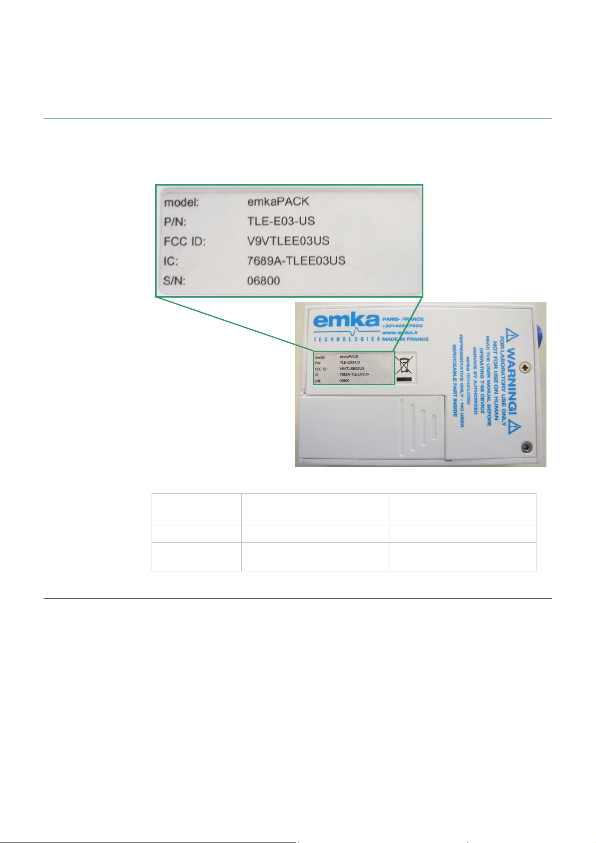
geographical region of use
emkaPACK transmitters are specific to the geographical region of use. The part
number (P/N) on the back of the device (see figure) indicates the geographical
region of use of your device (see table below).
the telemetry system
geographical
region of use
Europe only TLE-E03
US and Canada
only
part number (p/n) compliance notice
TLE-E03-US
FCC ID : V9VTLEE03US
IC : 7689A-TLEE03US
for use in US only
This equipment has been tested and found to comply with the limits for a Class B
digital device, pursuant to Part 15 of the FCC Rules. These limits are designed to
provide reasonable protection against harmful interference. This equipment
generates, uses, and can radiate radio frequency energy and, if not installed and
used in accordance with the instructions, may cause harmful interference to radio
communications. However, there is no guarantee that interference will not occur in
a particular installation. If this equipment does cause harmful interference, which
can be determined by turning the equipment off and on, the user is encouraged to
try to correct the interference by one of the following measures:
• reorient or relocate the receiving antenna
• increase the separation between the equipment and receiver
• connect the equipment to an outlet on a circuit different to that of the receiver
• consult emka TECHNOLOGIES
______________________________________________________________________________________________________________________________
emka TECHNOLOGIES page 3
Page 4

emkaPACK non-invasive telemetry transmitter user manual version 1.4 rev.1
You do not need to apply for a license to operate the emkaPACK non-invasive
telemetry transmitter. Do not attempt to open the emkaPACK.
Any changes or modifications in the emka
emka TECHNOLOGIES could void your authority to operate this equipment.
emka TECHNOLOGIES SA, 59, boulevard Général Martial Valin, 75015, Paris,
France, declares that device TLE-E03-US complies with Part 15 of the FCC Rules.
Operation is subject to the following two conditions: (1) the device may not cause
harmful interference, and (2) the device must accept any interference received,
including interference that may cause undesired operation.
for use in Canada only
emka TECHNOLOGIES SA, 59, boulevard Général Martial Valin, 75015, Paris,
France, déclare que l’appareil TLE-E03-US respecte la règlementation CNR-210 de
l’Industrie du Canada. L'utilisation de ce dispositif est autorisée seulement aux
deux conditions suivantes : (1) il ne doit pas produire de brouillage, et (2)
l'utilisateur du dispositif doit être prêt à accepter tout brouillage radioélectrique
reçu, même si ce brouillage est susceptible de compromettre le fonctionnement du
dispositif.
Attention: Tous changements ou modifications sur l’emka
expressément approuvé par emka TECHNOLOGIES pourrait annuler votre autorité
à utiliser cet appareil.
emka TECHNOLOGIES SA, 59, boulevard Général Martial Valin, 75015, Paris,
France, declares that the device TLE-E03-US complies with RSS-210 of Industry
Canada. Operation is subject to the following two conditions: (1) the device may not
cause harmful interference, and (2) the device must accept any interference
received, including interference that may cause undesired operation.
Caution: Any changes or modifications in the emka
approved by emka TECHNOLOGIES could void your authority to operate this
equipment.
PACK that are not expressly approved by
PACK qui ne sont pas
PACK that are not expressly
______________________________________________________________________________________________________________________________
emka TECHNOLOGIES page 4
Page 5

important notices
disclaimer
The hardware is exclusively designed for scientific research on the physiology of
laboratory animals. When this equipment is used, research animals should remain
confined to their usual laboratory cages.
All the hardware and software materials described in this user manual are not
intended to be used, and should not be used in human experimentation or applied
to humans in any way.
verification
emka TECHNOLOGIES hardware and software are extensively tested and
calibrated before leaving our factory or warehouse. Researchers should
independently verify the basic accuracy of materials delivered.
warranty
the telemetry system
safety warning
copyright
All material delivered by emka TECHNOLOGIES has a warranty against defects in material
and workmanship for a period of one year from the date of shipment (as
evidenced by receipts or other documentation).
repair or replace equipment that proves to be defective during the warranty
period. This warranty covers parts and labor.
The warranty becomes invalid if the material is not used in accordance with this
user manual.
emka TECHNOLOGIES believes that the information provided in this document is
accurate. Our document has been reviewed for technical accuracy. In the event
that technical or typographical errors exist, emka TECHNOLOGIES reserves the
right to make changes to subsequent editions of this document without prior
notice to holders of this edition. The reader should contact
if errors are suspected.
If material is not used in accordance with this user manual, electrical protection
provided by the hardware material may be impaired.
This manual contains all information about which precautions to take to avoid
injury due to electrical shock. Please read this manual before using the
non-invasive telemetry transmitter.
emka TECHNOLOGIES will, at its option,
emka TECHNOLOGIES
emkaPACK
Under the copyright laws, this publication may not be reproduced or transmitted in
any form, electronic or mechanical, including photocopying, recording, storing in
an information retrieval system, or translating, in whole or in part, without the prior
written consent of
______________________________________________________________________________________________________________________________
emka TECHNOLOGIES page 5
emka TECHNOLOGIES SA.
Page 6

emkaPACK non-invasive telemetry transmitter user manual version 1.4 rev.1
table of contents
chapter 1 the telemetry system ........................................................................10
chapter 2 emkaPACK transmitter ...................................................................12
2.1 description ........................................................................................................................................12
2.2 acquired parameters........................................................................................................................14
chapter 3 setting up the emkaPACK transmitter.............................................16
3.1 what is supplied ................................................................................................................................16
3.2 setting up the emkaPACK transmitter.............................................................................................16
chapter 4 running sessions .............................................................................. 18
chapter 5 maintenance ................................................................................... 22
chapter 6 extending functionality..................................................................... 23
chapter 7 frequently asked questions ............................................................. 24
7.1 emkaPACK transmitter..................................................................................................................... 24
7.2 ecg .................................................................................................................................................. 24
7.3 activity ............................................................................................................................................. 25
chapter 8 troubleshooting ............................................................................... 26
chapter 9 recommendations ........................................................................... 28
chapter 10 technical specifications .................................................................. 29
chapter 11 good laboratory practice ................................................................ 30
11.1 validation ......................................................................................................................................... 30
11.2 maintenance................................................................................................................................... 30
chapter 12 technical support ............................................................................31
12.1 internet site......................................................................................................................................31
12.2 your emka TECHNOLOGIES contacts ...........................................................................................31
chapter 13 customer feedback........................................................................ 32
13.1 support form................................................................................................................................... 32
13.2 feedback on this user manual........................................................................................................ 33
13.3 general feedback form................................................................................................................... 34
______________________________________________________________________________________________________________________________
emka TECHNOLOGIES page 6
Page 7

the telemetry system
table of figures
figure 1 a standard telemetry system installed by emka TECHNOLOGIES ............................. 10
figure 2 emkaPACK number .................................................................................................. 12
figure 3 emkaPACK transmitter serial number (S/N).............................................................. 12
figure 4 ecg connector and primary connectors.................................................................... 13
figure 5 secondary connectors (markings) ............................................................................ 13
figure 6 emkaPACK transmitter and led................................................................................. 14
figure 7 clips and banana connectors for ecg measurements ............................................... 16
figure 8 standard placement of electrodes ............................................................................ 19
figure 9 electrode placement in alternative ecg configuration ............................................... 19
figure 10 current flows in the alternative ecg configuration .................................................... 19
figure 11 placing bandaging around electrodes and wires......................................................20
figure 12 emkaPACK transmitter in place...............................................................................20
figure 13 example placement of electrodes for 1 lead ecg (lead II) ........................................ 21
table of tables
table 1 standards for color coding for ecg electrodes............................................................ 14
table 2 calibration values for ecg signal ................................................................................. 16
table 3 calibration values for activity signal ........................................................................... 17
table 4 technical specifications ..............................................................................................29
______________________________________________________________________________________________________________________________
emka TECHNOLOGIES page 7
Page 8

emkaPACK non-invasive telemetry transmitter user manual version 1.4 rev.1
about this manual
This document tells you how to use the emkaPACK for the acquisition of ecg and
activity data.
For customers new to telemetry, chapter 1 is a brief overview of the telemetry
system from emka TECHNOLOGIES.
PACK transmitter, while chapter 3 'setting up the
PACK transmitter. chapter 9 'recommendations'
conventions
chapter 2 describes your emka
emkaPACK transmitter' and chapter 4 'running sessions' provide practical
guidance on using the emka
contains important information concerning which the types of batteries to use with
your emka
If you have any questions or encounter any problems, the solution is likely to be
found in this manual, in particular chapter 7 'frequently asked questions' or chapter
8 'troubleshooting'.
PACK transmitter.
The different types of information given in the text are described below.
note: note.
Text in this format alerts you to a note, comment, or specific information.
technical note: technical note.
Text in this format alerts you to a note, comment, or specific information of a
technical nature.
important! important note.
Text in this font alerts you to important information.
caution! caution note.
Text in this font warns you of precautions to take to avoid danger, injury, the loss of
data, or a system crash.
equipment symbols
The different types of symbols on the device are described below.
Attention, consult accompanying documents.
Battery
related documentation
The following documents may also be of interest to you.
emkaPACK non-invasive telemetry system application note - for an overview of
telemetry
______________________________________________________________________________________________________________________________
emka TECHNOLOGIES page 8
Page 9

the telemetry system
emkaPACK telemetry receiver user manual
iox2 user manual - iox2 is emka TECHNOLOGIES‘ software solution for acquiring,
analyzing and storing data
ecgAUTO user manual - ecgAUTO is emka TECHNOLOGIES’ ecg analysis software
______________________________________________________________________________________________________________________________
emka TECHNOLOGIES page 9
Page 10
emkaPACK non-invasive telemetry transmitter user manual version 1.4 rev.1
chapter 1 the telemetry system
The telemetry system from emka TECHNOLOGIES is intended for use in preclinical
research, primarily toxicology and safety pharmacology studies.
It is a non-invasive, or external, system that acquires biological data from large
subjects such as dogs and non-human primates then transmits these data
wirelessly to a data acquisition station.
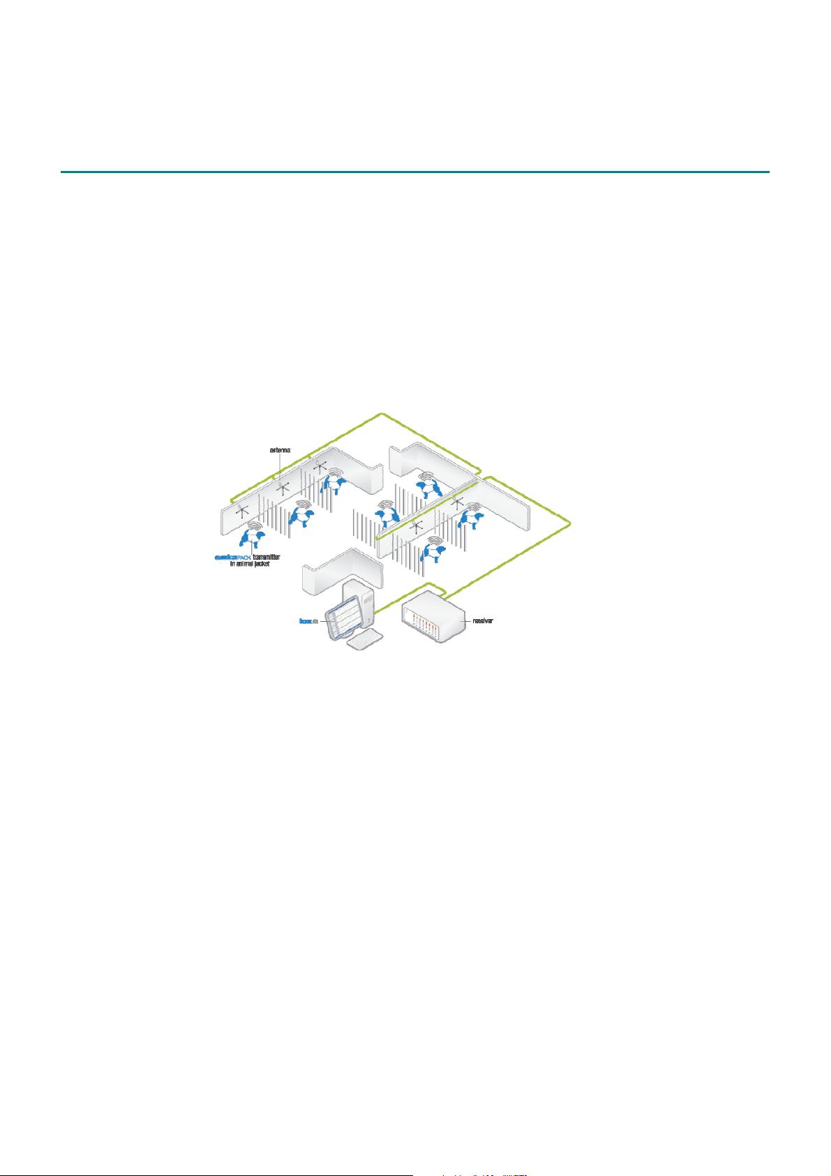
The different components of the telemetry system are shown in figure 1. This is a
standard set-up consisting of one antenna per cage and a small number of
subjects (to aid understanding, only key components and connections are shown).
figure 1 a standard telemetry system installed by emka TECHNOLOGIES
The different components of a standard telemetry system are as follows:
emkaPACK transmitter
The emka
jacket pocket on the back of the subject. Each emka
PACK transmitter is a compact and durable unit that fits neatly into a
PACK transmitter collects,
conditions, converts (to digital), and transmits physiological signals on a specific
frequency channel.
antenna
receives the transmitted signals, and is connected to the receiver module, directly
or via an antenna network.
receiver mainframe
houses and powers the receiver modules
emka
PACK receiver module
Each is tuned to a specific frequency channel, and forms a pair with a specific
emka
PACK transmitter. The modules slot inside the receiver mainframe.
versatile antenna adapter (VAA) (not shown on figure)
One or more VAAs combine to form an antenna network. Their role is to combine
and/or split the radio signal going from one or more antennas to one or more
______________________________________________________________________________________________________________________________
emka TECHNOLOGIES page 10
Page 11

the telemetry system
receiver modules. This allows greater flexibility when planning experiments (for
example, with a VAA, a particular emka
PACK can be used in different pens in
different recording sessions).
workstation
every setup contains at least one workstation equipped with a data acquisition card
and software for acquiring, analyzing and storing data. In figure above, iox2 is
used for acquisition, analysis and storage. For ecg data, advanced analysis can be
carried out with ecgAUTO software.
______________________________________________________________________________________________________________________________
emka TECHNOLOGIES page 11
Page 12

emkaPACK non-invasive telemetry transmitter user manual version 1.4 rev.1
chapter 2 emkaPACK transmitter
The emkaPACK transmitter performs collection, conditioning (including
amplification), analog-to-digital conversion, and transmission of ecg and activity.
It runs on two AA/R6 alkaline batteries providing continuous acquisition of 7-lead
ecg and activity data for an average of 80 hours.
With regard to battery choice:
• it is strongly recommended to avoid high-power batteries (see chapter 9).
• it is preferable to use single-use (disposable) rather than rechargeable
batteries (see FAQ "can I use rechargeable batteries?" in chapter 7).
The emkaPACK transmitter does not have a power switch. It is automatically
switched on and off when the ecg cable is connected and disconnected.
2.1 description
2.1.1 emkaPACK number
The corresponding receiver module has the same number (figure 2).
figure 2 emkaPACK number
2.1.2 serial number (S/N)
A unique serial number (S/N) is found on the back of each emkaPACK (figure 3).
figure 3 emkaPACK transmitter serial number (S/N)
______________________________________________________________________________________________________________________________
emka TECHNOLOGIES page 12
Page 13

2.1.3 ecg connector
The ecg cable is connected to the ecg
2.1.4 primary connectors
These connectors are used to connect to modules for the acquisition of
physiological signals other than ecg and activity.
emkaPACK transmitter
LEADS connector (figure 4).
figure 4 ecg connector and primary connectors
2.1.5 secondary connectors
These connectors connect to modules for the acquisition of physiological signals
other than ecg and activity (figure 5).
These connectors are not fitted on the emkaPACK as standard, because they are
only for use with modules by emka TECHNOLOGIES. Nevertheless, markings are
provided on the emkaPACK for customers who purchase the modules (figure 5).
(In this case, the connectors may be fitted by customers themselves or by
emka TECHNOLOGIES.)
figure 5 secondary connectors (markings)
______________________________________________________________________________________________________________________________
emka TECHNOLOGIES page 13
Page 14

emkaPACK non-invasive telemetry transmitter user manual version 1.4 rev.1
2.1.6 led
The led (figure 6) indicates the progress of the boot-up procedure.
figure 6 emkaPACK transmitter and led
2.2 acquired parameters
2.2.1 ecg
The emkaPACK is used to obtain ecg data from large animals, such as dogs,
primates and pigs. Three configurations are possible
• 1-lead ecg, using a 3-wire ecg cable
• 6-lead ecg, using a 4-wire ecg cable, for obtaining the standard leads,
namely three Einthoven bipolar leads (I, II, III) and three Goldberger unipolar
leads (aVR, aVL, aVF)
• 7-lead ecg, using a 5-wire ecg cable - 6-lead ecg as above plus one
unipolar chest lead (Wilson lead)
The colors used for the different wires are those defined by standards (Table 1).
location IEC (Europe) AAMI (US, Japan)
right arm (RA) red white
left arm (LA) yellow black
right leg (RL) black green
left leg (LL) green red
chest lead variable
(gray for emka
TECHNOLOGIES)
variable
(gray for emka TECHNOLOGIES)
table 1 standards for color coding for ecg electrodes
When placing an order for an emka
PACK, customers must specify which ecg
configuration they intend to use because the internal software of the emkaPACK
must be configured. In addition, the appropriate ecg cable is supplied.
______________________________________________________________________________________________________________________________
emka TECHNOLOGIES page 14
Page 15

2.2.2 activity
emkaPACK transmitter
The 3-axis accelerometer inside the emkaPACK transmitter measures movement in
each axis every 2 ms.
The emkaPACK calculates an activity signal (Act) for intervals of 192 ms as follows.
εAct ++=
x
with
εx = x
εy = y
εz = z
2
- ¯x
n
- ¯yn where yn is the y-axis value for acquisition n Æ n+95
n
- ¯zz
n
2
ε
y
n
n
2
ε
z
where xn is the x-axis value for acquisitions n Æ n+95
where zn is the z-axis value for acquisition n Æ n+95
______________________________________________________________________________________________________________________________
emka TECHNOLOGIES page 15
Page 16
emkaPACK non-invasive telemetry transmitter user manual version 1.4 rev.1
chapter 3 setting up the emkaPACK transmitter
3.1 what is supplied
• ecg cable containing 3, 4 or 5 wires, as requested by the customer.
Electrodes provided with 4-and 5-wire cables are color coded in
accordance with IEC standards (on request, emka
cable color coded according to AAMI standards).
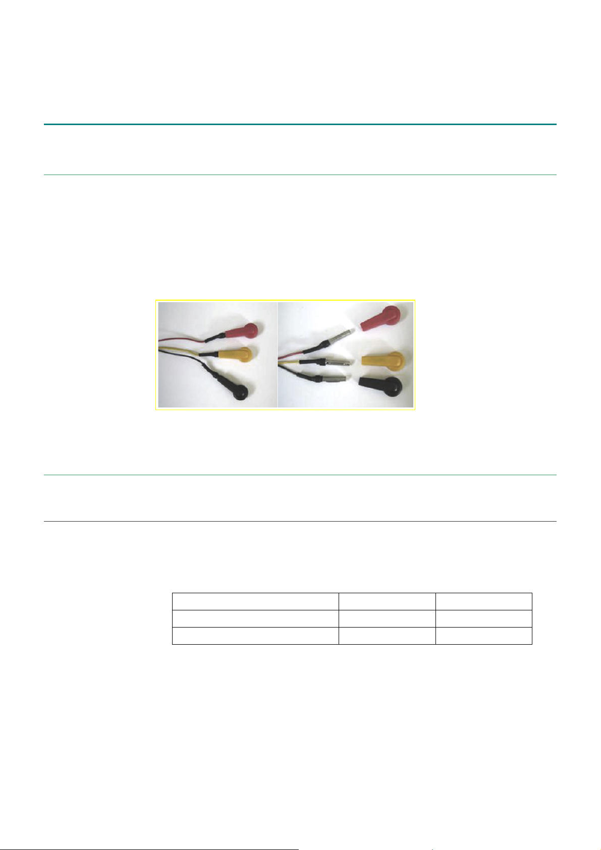
• electrode connectors (Comepa) - both banana and clip connectors are
supplied (figure 7). The clip connector is inserted around the banana
connector. Therefore, simply remove the clip connector if you want to use
the banana connectors.
TECHNOLOGIES will supply
figure 7 clips and banana connectors for ecg measurements
3.2 setting up the emkaPACK transmitter
The setup involves calibration only.
3.2.1 calibration of ecg signal
The ecg measurement chain is factory calibrated and temperature compensated.
You simply enter the two pairs of calibration values directly into your data
acquisition software:
low high
Physical value (mV)
Output signal amplitude (V)
table 2 calibration values for ecg signal
If you are using iox2, this 'manual calibration' is done in 'two-points calibration
(manual)'.
To perform calibration, you can also use a device that simulates ecg output. You
may use the ecg calibrator from emka TECHNOLOGIES for this purpose (sold
separately).
-5 5
-5 5
______________________________________________________________________________________________________________________________
emka TECHNOLOGIES page 16
Page 17

3.2.2 calibration of activity signal
The integrated activity measurement system is factory calibrated and temperature
compensated.
You simply enter the two pairs of calibration values (voltage and physical quantity)
directly into your data acquisition software:
low high
Physical value (m.s-2)
Output signal amplitude (V)
table 3 calibration values for activity signal
If you are using iox2, this 'manual calibration' is done in 'two-points calibration
(manual)'.
setting up the emkaPACK transmitter
0 1
-5 -1.45
______________________________________________________________________________________________________________________________
emka TECHNOLOGIES page 17
Page 18

emkaPACK non-invasive telemetry transmitter user manual version 1.4 rev.1
chapter 4 running sessions
This chapter describes how to run a session for the acquisition of 7-lead ecg and
activity in dogs.
It is assumed that the telemetry setup also includes iox2 (a software application for
acquiring, analyzing and storing data) and you are using clothing from Lomir
(custom-designed for the emkaPACK).
4.1.1 requirements
• ecg cable (supplied)
• banana and clip connectors (supplied)
• adhesive electrodes (available from emka TECHNOLOGIES separately)
• clippers
• gauze sponge
• alcohol for disinfecting the skin
• white tape
• undershirt
• jacket
• self-adherent bandaging (optional), such as Vetrap
United Kingdom)
TM
(3M, Bracknell, Berks,
4.1.2 running a session
1. Insert new batteries.
subject preparation - place the electrodes
There are two possible ecg configurations.
standard configuration
1. Shave the skin on the underside of the subject in five different areas as
follows:
• two circles of 5 cm diameter below the left front leg and the right front leg
(LA and RA electrodes)
• two circles of 5 cm diameter mid-way between the front and rear legs, on
the left side and the right side (LL and RL electrodes)
• one circle of 5 cm diameter 7 cm below the front left electrode (V
electrode), i.e. under the heart
2. Wipe each area with gauze sponge and alcohol and allow to air dry.
3. Connect the electrodes to the wires of the ecg cable.
4. Place the adhesive electrodes on the bare skin, at the correct site (figure 8).
Press around the edge of the electrode but not in the centre.
______________________________________________________________________________________________________________________________
emka TECHNOLOGIES page 18
Page 19

alternative configuration
running sessions
figure 8 standard placement of electrodes
Experience has shown that this configuration can also provide high-quality ecg
signals, notably in beagles. The placement of electrodes for 6-lead ecg (shown in
figure 9, AAMI colours) is adapted to the position of the heart (more central within
the chest cavity), with the current flows crossing in the subject’s chest (figure 10).
All the electrodes should be aligned along an imaginary circle drawn around the
subject's chest and be located away from its normal range of movement.
figure 9 electrode placement in alternative ecg configuration
figure 10 current flows in the alternative ecg configuration
______________________________________________________________________________________________________________________________
emka TECHNOLOGIES page 19
Page 20
emkaPACK non-invasive telemetry transmitter user manual version 1.4 rev.1
subject preparation - dress the subject
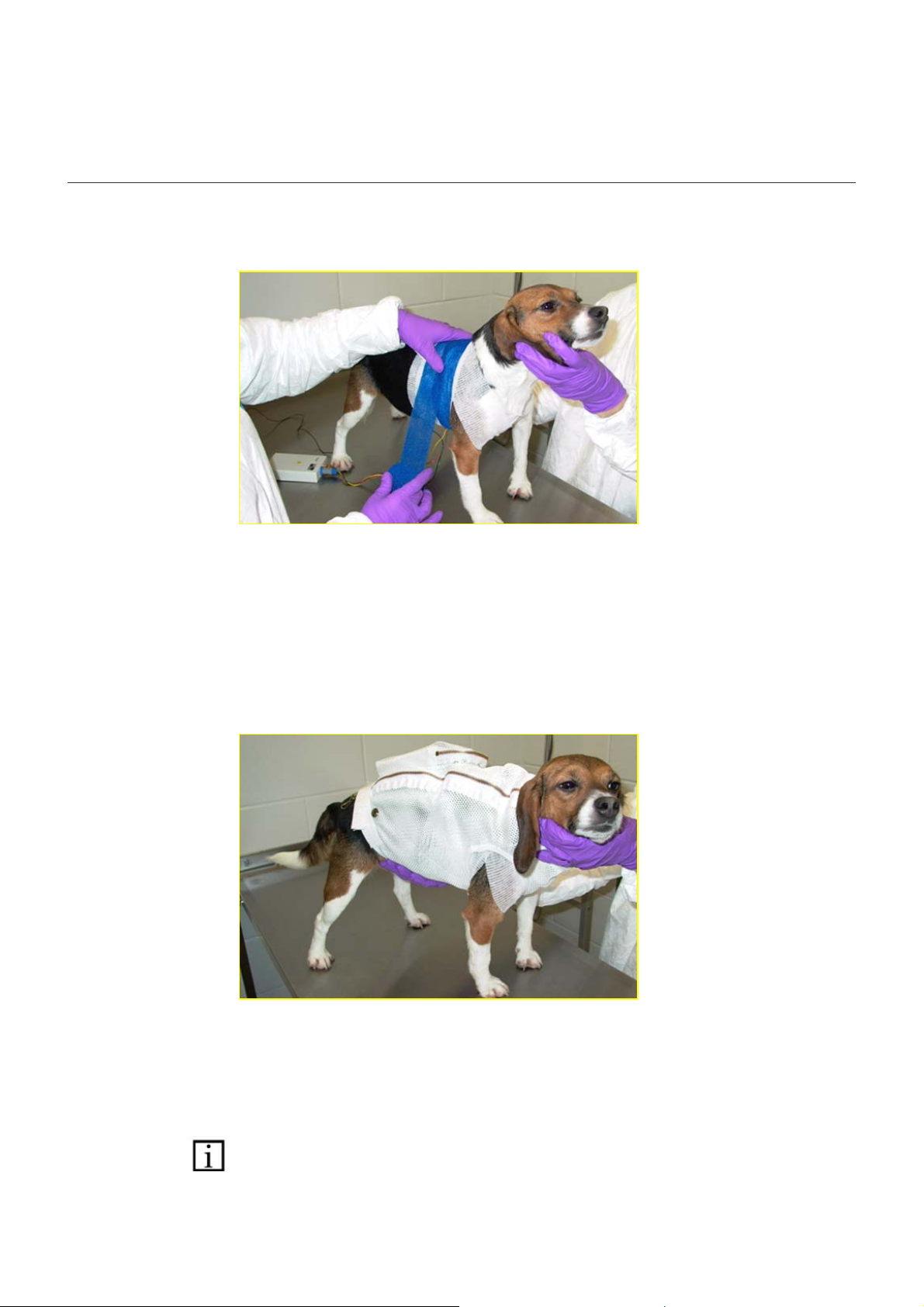
5. Secure the wires in position with the undershirt. As an alternative or if the
undershirt is not sufficient, use white tape and bandaging (figure 11). The
bandaging must not be too tight as this will impair the animal's breathing.
figure 11 placing bandaging around electrodes and wires
6. Place the jacket around the subject.
7. Place the emkaPACK transmitter in the jacket pocket.
8. Ensure that there are no loose wires hanging out, as these are liable to be
chewed or to catch on objects. The subject is ready (figure 12).
figure 12 emkaPACK transmitter in place
The procedure is the same for other ecg configurations (such as 6-lead ecg) with
steps 1 to 4 modified accordingly. figure 13 shows electrode placement for
obtaining 1-lead ecg (for lead II ).
important! all the wires of the ecg cable must be connected to the subject, even if
you are not using them (for example, if you wish to acquire 1-lead ecg with a 5-wire
cable). Otherwise, the signal will be inaccurate. ecg cable can be ordered from
emka
______________________________________________________________________________________________________________________________
TECHNOLOGIES.
emka TECHNOLOGIES page 20
Page 21

running sessions
figure 13 example placement of electrodes for 1 lead ecg (lead II)
note: the emkaPACK transmitter can be used to obtain ecg data from other large
animals, such as primates and pigs.
power up
Plug the ecg cable into the ecgLEADS connector to turn on the emkaPACK
transmitter. It then performs a boot procedure. During this procedure, which only
takes a few seconds, the led goes from off to solid green (i.e. not flashing). After
successful boot-up, the led simply goes off.
If the LED does not go on or goes solid red, there is a potential problem with the
emkaPACK transmitter. If this happens, switch off the emkaPACK transmitter (by
disconnecting the ecg cable), check the connections and batteries, then switch it
on again. If the problem persists, please contact emka
'Technical support' chapter).
recording session
No particular action is required during recording sessions.
If the battery charge falls below a certain level, the 'low battery' led lights up on the
corresponding receiver module.
4.1.3 after sessions
At the end of the experiment, disconnect the ecg cable from the emkaPACK
transmitter to switch off the power.
The emkaPACK transmitter should be stored in a cool dry place. Keep it away from
sunlight and other sources of heat. Keep it away from sources of magnetism.
If you will not be using the emka
batteries.
TECHNOLOGIES (see
PACK transmitter for some time, remove the
______________________________________________________________________________________________________________________________
emka TECHNOLOGIES page 21
Page 22

emkaPACK non-invasive telemetry transmitter user manual version 1.4 rev.1
chapter 5 maintenance
For accurate data, the calibration of the telemetry system must be verified on a
regular basis. At installation, emka TECHNOLOGIES provides a calibration certificate
valid for one year. Certificate renewal (verification or recalibration) is performed as
part of maintenance contracts.
Calibration should be performed as often as necessary. In practice, the frequency
of calibration is imposed by internal regulations or is indicated in certain situations,
e.g. exposure to highly variable temperature, humidity, shock etc.
Check the cables and connectors regularly.
If you will not be using the emka
batteries.
PACK transmitter for some time, remove the
______________________________________________________________________________________________________________________________
emka TECHNOLOGIES page 22
Page 23

chapter 6 extending functionality
emka TECHNOLOGIES sells a range of modules for the acquisition of different
types of signals.
• skin temperature
• blood pressure, non-invasively (nibp module) or in combination with a vascular
access port (t-PRESS module)
• lung volume (emka
Please contact emka TECHNOLOGIES for more information about using your
emkaPACK with the above modules.
BELT module)
extending functionality
______________________________________________________________________________________________________________________________
emka TECHNOLOGIES page 23
Page 24

emkaPACK non-invasive telemetry transmitter user manual version 1.4 rev.1
chapter 7 frequently asked questions
7.1 emkaPACK transmitter
can I use the emkaPACK transmitter for eeg measurements?
Each type of bioelectric potential has a characteristic amplitude, frequency, signalnoise ratio, etc and requires specially designed components. Currently, emkaPACK
telemetry system is designed to measure ecg only. However please let us know if
you are interested in using emka
biopotentials. Our aim is to satisfy our customers' requirements.
can I use rechargeable batteries?
Yes, but it is recommended to use single-use batteries to reduce the risk and the
duration of recording gaps during experimental sessions. This is because:
• single-use batteries generally provide current for longer than fully-charged
rechargeable batteries.
• single-use batteries generally have a more gradual discharge curve. This
means that they will reach full discharge 3-4 hours after the 'low-battery'
warning appears (versus 10-15 minutes with most rechargeable batteries).
Please check the website www.emka.fr (in English) to see the latest options. If you
cannot find the product you need for your experiments, please contact us.
PACK transmitter for measuring other
is there a help-line?
The answers to most technical issues are contained within this user manual, in
particular, the 'troubleshooting' and 'frequently asked questions' chapters.
If you cannot find a solution in this manual, you may:
• check the website at www.emka.fr (in English)
o products >> software
o applications >> telemetry
o services >> technical support
o services >> FAQs
• contact emka
• fax back the Support Form in the 'customer feedback' chapter
TECHNOLOGIES (see 'technical support' chapter)
7.2 ecg
how often do I have to calibrate the ecg module?
Generally, we recommend that users perform calibration with a device that
simulates ecg signals (e.g. ecg calibrator from emka
month. More frequent calibration may be imposed by internal regulations or
indicated in certain situations, e.g. if the emka
variable environmental conditions (temperature, humidity, shock etc).
TECHNOLOGIES) at least once a
PACK transmitter is subject to highly
______________________________________________________________________________________________________________________________
emka TECHNOLOGIES page 24
Page 25

what type of ecg data can I acquire using the emka
frequently asked questions
PACK transmitter?
As part of a telemetry set-up, emka
PACK transmitter may be used for acquiring
• 1-lead ecg
• 6-lead ecg (3 Einthoven bipolar, 3 Goldberger unipolar)
• 7 lead ecg (
3 Einthoven bipolar, 3 Goldberger unipolar, 1 unipolar chest lead)
is it possible to change ecg configuration, e.g. from 6-lead ecg to 7-lead ecg ?
Yes, it is possible to change ecg configuration. However, the system must be
adapted by using appropriate cable and reconfiguring emka
internal software (this is done by emka
TECHNOLOGIES).
Correct cable and reconfiguration are particularly important if you decide to 'downgrade' ecg configuration (e.g. 7-lead to 6-lead, or 6-lead to 1-lead). If the
appropriate cable is not used, unused electrodes may cause interference. To
ensure accurate signals, every wire of the ecg cable must be connected to the
subject, regardless of whether its signal will be acquired.
can I make eeg measurements using emkaPACK transmitter?
Currently this is not possible. However please let us know if you are interested in
using emkaPACK transmitter for this purpose. Our aim is to satisfy our customers'
requirements.
7.3 activity
PACK transmitter
how often do I have to calibrate the activity option?
The activity option is factory calibrated; the accelerometer is designed to provide
the same voltage output for a given activity level over time.
You only need to enter pairs of calibration values (voltage and physical quantity)
directly into your data acquisition software. This 'manual calibration' therefore is not
a full calibration because you type in the quantity rather than physically apply it.
______________________________________________________________________________________________________________________________
emka TECHNOLOGIES page 25
Page 26

emkaPACK non-invasive telemetry transmitter user manual version 1.4 rev.1
chapter 8 troubleshooting
the LED does not go on when the ecg connector/power plug is connected
Possible causes and solutions:
One or both batteries are the wrong way.
Æ Place the batteries the right way.
One or both batteries has run out.
Æ Insert new batteries.
emka
Æ Contact technical support (See 'technical support' chapter)
the LED is solid red
Possible causes and solutions:
Initialization has failed.
Æ Check all connections.
emka
Æ Contact Technical support (See 'technical support' chapter)
PACK transmitter is defective.
PACK transmitter is defective.
there are no signals from one of the emkaPACK transmitters (the 'source on' led of the
corresponding receiver module is off)
Æ Ensure that the antenna networks (the VAAs) are powered up
Æ Check that the corresponding emka
PACK transmitter is working.
- are the batteries the right way?
- have the batteries run out?
Æ Insufficient transmission range
Under normal conditions, the settings of each emka
PACK transmitter should ensure
continuous coverage, wherever the subject is located
there are no signals from any of the emka
PACK transmitters
Possible causes and solutions:
There is no power supply in the receiver mainframe:
Æ Check the power supply module in the receiver mainframe (the led should be
green): Has the fuse blown? Is the power switched on?
there is no physiological signal
Æ Check the connections.
Æ Check that the electrodes connectors have not become disconnected.
the ecg signal is noisy
Æ Check that all wires are connected to the electrodes.
Æ Check that the electrodes are properly stuck to the subject
______________________________________________________________________________________________________________________________
emka TECHNOLOGIES page 26
Page 27

chapter 9 recommendations
emka TECHNOLOGIES strongly recommends the use of DURACELL
PROCELL AA/LR6 2700 mAh alkaline batteries.
After extensive testing, we found DURACELL PROCELL batteries to be reliable as
well as powerful enough to run emka
information for 7-lead ecg and activity. These batteries are reasonably priced
(around EUR 0.35 or US$ 0.50 each).
Other batteries exist, some of which have a higher energy capacity. For example,
the ENERGIZER ULTIMATE LITHIUM battery has close to twice the energy of a
DURACELL PROCELL. Although their cost is disproportionately higher, some
customers may find them attractive because of their high energy content.
However, we strongly recommend against the use of high-power
batteries to run emka
following facts:
• emka
PACK is powered by two 1.5V batteries running in series, providing a total
of 3V.
• emka
PACK is fitted with an electronics module that provides its key
components a stable 3V power supply even when available battery voltage
drops below the nominal 3V value (as occurs towards the end of battery life).
• emkaPACK does not have an equivalent feature that stabilizes voltage at 3V
when batteries provide a total voltage above 3V.
• high-power batteries usually provide voltage well above 1.5V (typically up to
1.8V), and their voltage remains above 1.5V through most of their life span.
• running emka
PACK with voltage above its nominal 3V has undesirable effects
on the amplitude of the transmitted signal. For example, going from a voltage of
3V to 3.6V causes a decrease of around 15% in the output amplitude of ecg or
activity.
To avoid difficulties and inconsistencies between calibration and
measurements, all customers are advised to use alkaline DURACELL
PROCELL or equivalent batteries.
These recommendations should not present a problem for the majority of our
customers. However, if you believe that the recommended batteries will not have
sufficient power, please contact emka TECHNOLOGIES SA (France) for advice on
how to proceed and/or to find a solution.
Future versions of emka
batteries without any undesirable effects on signal amplitude.
PACK transmitters; this recommendation is based on the
PACK transmitters will be designed to accept high-power
recommendations
PACK for 80 hours when transmitting
______________________________________________________________________________________________________________________________
emka TECHNOLOGIES page 27
Page 28

emkaPACK non-invasive telemetry transmitter user manual version 1.4 rev.1
chapter 10 technical specifications
parameter description value unit notes
Vcc
Icc
Trd
Lbt
Fa
Tst
Top
HRs
HRo
Dimensions
Weight
Battery
supply voltage 1.1 3 3.3 V DC
supply current 8 13 30 mA Depends on factory settings.
transmission distance 0.75 10 m Depends on factory settings
low battery indication 1.7 1.8 1.9 V See calibration certificate
functional autonomy 48 72 80 Hours Depends on transmission
storage temperature -10 20 60 °C
operating temperature 10 35 50 °C
storage humidity 20 40 80 %RH
operating humidity 30 50 70 %RH
length:
width:
depth:
weight (with batteries) 180 g
2 x AA/LR6 type battery 1.5 V Duracell PROCELL 2700 mAh
min typ max
117
78
27
mm
mm
mm
See calibration certificate
and environment
power and battery type
or equivalent alkaline model
recommended
ecg signal
Lo Freq
Hi Freq
Max offset
Aimax
Fs
Zi
G
Res
low cut-off frequency 0.7 Hz -3 dB
high cut-off frequency 250 Hz -3 dB
maximum input offset -75 0 +75 mV F < 0.7 Hz
max. input amplitude -4 1 +4 mV 0.7 < F < 250 Hz
sampling frequency 500 Hz
Input impedance of ecg
amplifier
signal amplification 1 V/mV see calibration certificate
amplitude resolution 7.8 µV
3.10
9
Ω
activity signal
Fs
AMax
______________________________________________________________________________________________________________________________
sampling frequency
Maxim acceleration
amplitude per axis (x, y or
z)
table 4 technical specifications
emka TECHNOLOGIES page 28
5.1 Hz
- 1.5 1.5 m.s
-2
Page 29

chapter 11 good laboratory practice
As part of its commitment to customer service, emka TECHNOLOGIES provides
assistance to customers to allow them to conduct studies according to good
laboratory practice. Assistance covers validation and maintenance.
11.1 validation
Telemetry systems from emka TECHNOLOGIES are developed according to high
quality assurance standards and have built-in features which allow them to be
successfully validated.
emka TECHNOLOGIES performs a validation of the system's accuracy, stability, and
reliability at installation, i.e. for your specific system configuration under your
specific operating procedures and your specific operating environment.
As the system provider, we know how the system operates; thus, we can provide
efficient validation assistance through our validation support service packages:
• support to customer and/or third-party package
• sample plan and test script models package
• tailored models package
• full validation process package
We provide assistance for the entire validation process.
good laboratory practice
11.2 maintenance
Our maintenance contracts provide you with assistance for any problems
encountered, and yearly controls.
______________________________________________________________________________________________________________________________
emka TECHNOLOGIES page 29
Page 30

emkaPACK non-invasive telemetry transmitter user manual version 1.4 rev.1
chapter 12 technical support
The answers to most technical issues are contained within this user manual. In
particular, the ‘troubleshooting’ and ‘frequently asked questions’ chapters contain
answers to the most commonly occurring issues.
If you cannot find a solution in this manual, please:
• check the website
• contact emka
• fax back the ‘support form’ in the ‘customer feedback’ chapter
12.1 internet site
TECHNOLOGIES
The website of emka TECHNOLOGIES at www.emka.fr contains a lot of information,
including technical support and services. We invite you to visit the following
sections:
• products >> hardware >> non-invasive telemetry
• applications >> telemetry
• services >> technical support
• services >> faq
12.2 your emka TECHNOLOGIES contacts
If you searched www.emka.fr and could not find the answers you need, contact
your local office or emka TECHNOLOGIES corporate headquarters.
emka
emka TECHNOLOGIES SA
59, bd. Général Martial Valin 75015 Paris - France
phone: + 33 (0)1 40 60 76 00 fax: +33 (0)1 40 60 65 55
sales and support office for North America
emka TECHNOLOGIES INC.
115 Hillwood Ave., Suite 203 Falls Church, VA 22046 - USA
phone: +1 (703) 237-9001 fax: +1 (703) 237-9006
TECHNOLOGIES corporate headquarters
______________________________________________________________________________________________________________________________
emka TECHNOLOGIES page 30
Page 31

chapter 13 customer feedback
13.1 support form
Photocopy this page and fill it out each time you encounter problems. Completing
this form accurately helps us to answer your question more effectively.
personal information:
name:
_______________________________________________________________________________
title/function:
_______________________________________________________________________________
company:
_______________________________________________________________________________
address:
_______________________________________________________________________________
fax/phone (please indicate which):
_______________________________________________________________________________
Describe the problem below.
_______________________________________________________________________________
_______________________________________________________________________________
_______________________________________________________________________________
_______________________________________________________________________________
_______________________________________________________________________________
_______________________________________________________________________________
_______________________________________________________________________________
_______________________________________________________________________________
_______________________________________________________________________________
Please return the form by post or fax
emka TECHNOLOGIES (corporate headquarters)
59, bd. Général Martial Valin 75015 Paris - France / Fax: +33 (0)1 40 60 65 55
emka TECHNOLOGIES INC (sales and support office for North America)
115 Hillwood Ave., Suite 203 Falls Church, VA 22046 - USA
Fax: +1 (703) 237-9006
customer feedback
______________________________________________________________________________________________________________________________
emka TECHNOLOGIES page 31
Page 32

emkaPACK non-invasive telemetry transmitter user manual version 1.4 rev.1
13.2 feedback on this user manual
emka TECHNOLOGIES strongly encourages feedback on its products and services.
Please let us know what you think about this user manual by returning the form
below. This information will enable us to continue to improve our documentation.
My feedback concerns:
emkaPACK transmitter user manual version 1.4 rev.1 – August 2008
personal information:
name:
_______________________________________________________________________________
title/function: company:
_______________________________________________________________________________
address:
_______________________________________________________________________________
fax/phone (please indicate which):
_______________________________________________________________________________
Please tell us whether you think that this manual is (circle the correct answer)
• exhaustive Yes / No
• clear, easy to understand Yes / No
• well organized Yes / No
• useful Yes / No
If you have specific comments or suggestions for improving the manual, please
mention them here:
_______________________________________________________________________________
_______________________________________________________________________________
If there are any errors in the user manual, please describe them here (with page
number/ section)
_______________________________________________________________________________
_______________________________________________________________________________
_______________________________________________________________________________
Thank you for your time. Your feedback is valuable to us.
Please return the form by post or fax
emka TECHNOLOGIES (corporate headquarters)
59, bd. Général Martial Valin 75015 Paris - France / Fax: +33 (0)1 40 60 65 55
emka TECHNOLOGIES INC (sales and support office for North America)
115 Hillwood Ave., Suite 203 Falls Church, VA 22046 – USA
Fax: +1 (703) 237-9006
______________________________________________________________________________________________________________________________
emka TECHNOLOGIES page 32
Page 33

13.3 general feedback form
emka TECHNOLOGIES strongly encourages feedback on its products and
services.
This form may be used to provide feedback on any of our products and services.
This information will enable us to continue to provide quality products to meet your
needs.
product or service concerned:
_______________________________________________________________________________
personal information:
name:
_______________________________________________________________________________
title:
_______________________________________________________________________________
company:
_______________________________________________________________________________
address:
_______________________________________________________________________________
fax/phone (please indicate which):
_______________________________________________________________________________
provide your feedback below
_______________________________________________________________________________
_______________________________________________________________________________
_______________________________________________________________________________
_______________________________________________________________________________
_______________________________________________________________________________
_______________________________________________________________________________
_______________________________________________________________________________
_______________________________________________________________________________
Thank you for your time. Your feedback is valuable to us.
Please return the form by post or fax
emka TECHNOLOGIES (corporate headquarters)
59, bd. Général Martial Valin 75015 Paris - France / Fax: +33 (0)1 40 60 65 55
emka TECHNOLOGIES INC (sales and support office for North America)
115 Hillwood Ave., Suite 203 Falls Church, VA 22046 -
customer feedback
USA / Fax: +1 (703) 237-9006
______________________________________________________________________________________________________________________________
emka TECHNOLOGIES page 33
Page 34

emkaPACK non-invasive telemetry transmitter user manual version 1.4 rev.1
End of user manual.
Thank you for purchasing the emkaPACK transmitter as part of your telemetry
setup.
Our goal is to develop products and services that meet the needs of the research
community. As such we are attentive to all our customers and your feedback is
appreciated.
emka TECHNOLOGIES
emka
TECHNOLOGIES SA
59, bd. Général Martial Valin 75015 Paris - France
phone: + 33 (0)1 40 60 76 00 fax: +33 (0)1 40 60 65 55
emka
TECHNOLOGIES INC.
115 Hillwood Ave., Suite 203 Falls Church, VA 22046 - USA
phone: +1 (703) 237-9001 fax: +1 (703) 237-9006
www.emka.fr / www.emkatech.com
© 2008 emka
Because emka
TECHNOLOGIES SA. All contents Copyright. All rights reserved.
TECHNOLOGIES has a policy of continuous product improvement, we
reserve the right to change design and specifications without notice.
______________________________________________________________________________________________________________________________
emka TECHNOLOGIES page 34
 Loading...