

Page 1
TECHNICAL BULLETIN TB-6594
SmartLog Pro®
Installation, Operation and Maintenance
The SmartLog Pro® offers three operator identification
methods: HID OMNIKEY® proximity reader, barcode
scanner and touchscreen keypad. The five-inch color
touchscreen provides an intuitive user interface for easy
test operation and a clear indication of test results.
The operator average test time is 2 seconds. Internal
flash memory allows operators to continue using the
tester even if network failure were to occur. All test
transactions would download to the database once the
network connection is restored.
The TEAM5 Software can generate automated reports
that may be e-mailed to track short term and long term
corrective actions. Test limits and test parameters (wrist
strap only, footwear only, wrist strap and footwear, etc.)
may be customized with the software to meet special
requirements. The SmartLog Pro® is calibrated to NIST
traceable standards.
ESD Association Information
“Compliance verification should be performed prior to
each use (daily, shift change, etc.). The accumulation
of insulative materials may increase the foot grounder
system resistance. If foot grounders are worn outside
the ESD protected area testing for functionality
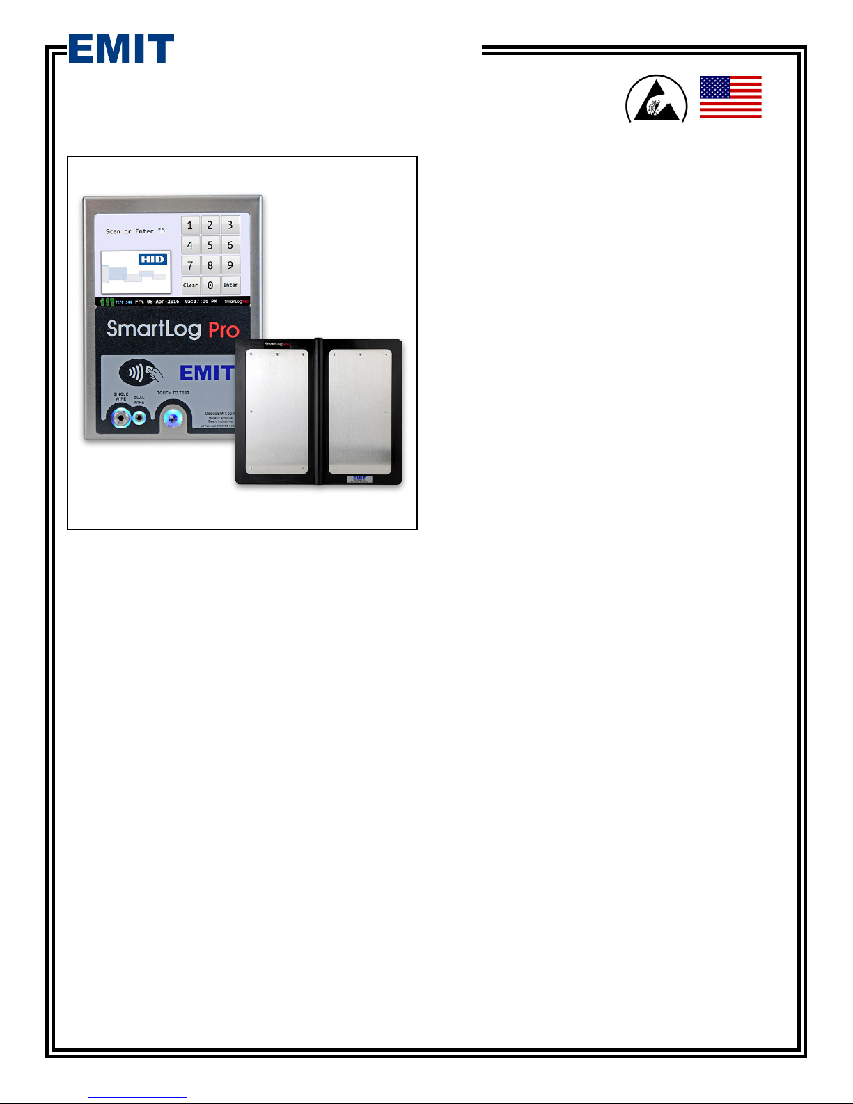
Figure 1. EMIT 50780 SmartLog Pro®
Description
The SmartLog Pro® verifies the functionality of an
operator’s wrist strap and footwear, logs the test results,
and controls access to an ESD Protected Area.
The default test limits are set to:
Wrist Strap: 750 kilohms to 10 megohms
Footwear: 750 kilohms to 35 megohms
All operator test activity is logged into a database
to meet the ANSI/ESD S20.20 requirements for
on-going quality control purposes. Each log entry
includes operator identification, test results, resistance
measurements, time, temperature and humidity.
Operator identification and access control is initiated
with the embedded HID OMNIKEY® proximity reader,
barcode scanner or touchscreen keypad. Access control
to an ESD Protected Area can be further enforced by
using the relay terminal on the SmartLog Pro®. It can
be connected to an electronic door lock or turnstile
to grant access only to those who have passed their
pre-defined ESD tests and been given clearance to the
area.
before reentry to the ESD protected area should be
considered.” ESD SP9.2 APPENDIX B - Foot Grounder
Usage Guidance
“Process monitoring (measurements) shall be conducted
in accordance with a Compliance Verification Plan that
identifies the technical requirements to be verified, the
measurements limits and the frequency at which those
verifications shall occur...Compliance verification records
shall be established and maintained to provide evidence
of conformity to the technical requirements.
The test equipment selected shall be capable of
making the measurements defined in the Compliance
Verification Plan.” (ANSI/ESD S20.20) section 7.3
ANSI/ESD S20.20 Table 1 Flooring-Footwear Systems
Technical Requirements Recommended Range “less
than 3.5 x 10⁷ ohms measured per ANSI/ESD STM
97.1.”
“Typical test programs recommend that wrist straps that
are used daily should be tested daily. However, if the
products that are being produced are of such value that
knowledge of a continuous, reliable ground is needed,
and then continuous monitoring should be considered or
even required.” (ESD Handbook ESD TR 20.20 section
5.3.2.4.4)
Note: SmartLog Pro® provides wrist strap test per IEC
61340-5-1 Clause A.1 and footwear testing per IEC
61340-5-1 Clause A.2 with upper limits < 3.5 x 10⁷
ohms.
Made in the
United States of America
EMIT - 3651 Walnut Avenue, Chino, CA 91710 • (909) 664-9980 • Website: DescoEMIT.com
TB-6594 Page 1 of 12
March 2018
© 2018 DESCO INDUSTRIES, INC.
Employee Owned
Page 2

Contents
3 System Overview
4 Items and Accessories
4 Packaging
5 Features and Components
6 Installation
6 Hardware Setup
7 10mm Wrist Cord Adapter
8 Relay Terminal
8 Network Setup
9 Test Limit Configuration
10 TEAM5 Software
11 Operation
12 Maintenance
12 Calibration
12 Specifications
12 Limited Warranty
EMIT - 3651 Walnut Avenue, Chino, CA 91710 • (909) 664-9980 • Website: DescoEMIT.com
TB-6594 Page 2 of 12
© 2018 DESCO INDUSTRIES, INC.
Employee Owned
Page 3
System Overview
SmartLog Pro®
Department
Manager
Supervisor
Department
Manager
PC with
TEAM5 Software
Department
Manager
SmartLog Pro®
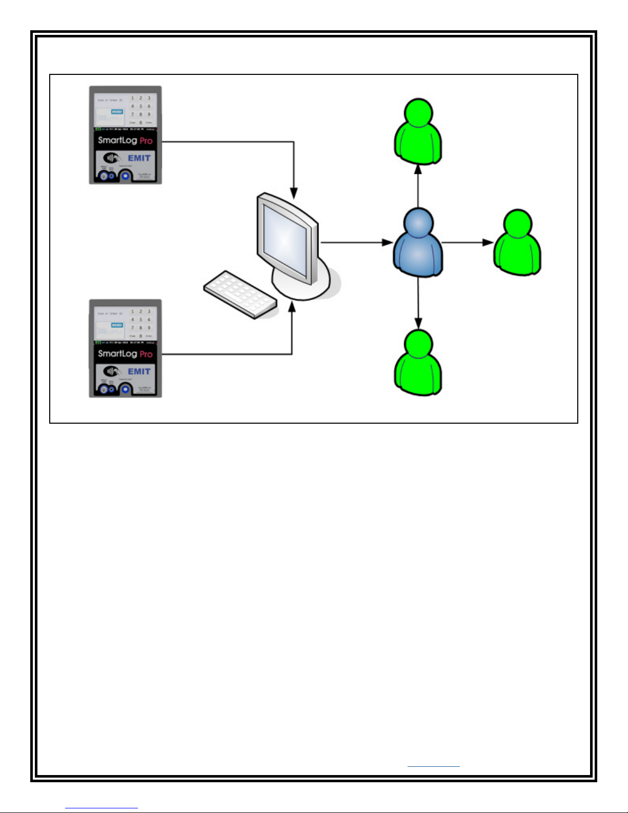
Figure 2. Illustration of the SmartLog Pro® System collecting and transferring ESD data to a central PC where it is
distributed to supervisors and department managers.
EMIT - 3651 Walnut Avenue, Chino, CA 91710 • (909) 664-9980 • Website: DescoEMIT.com
TB-6594 Page 3 of 12
© 2018 DESCO INDUSTRIES, INC.
Employee Owned
Page 4
Items and Accessories
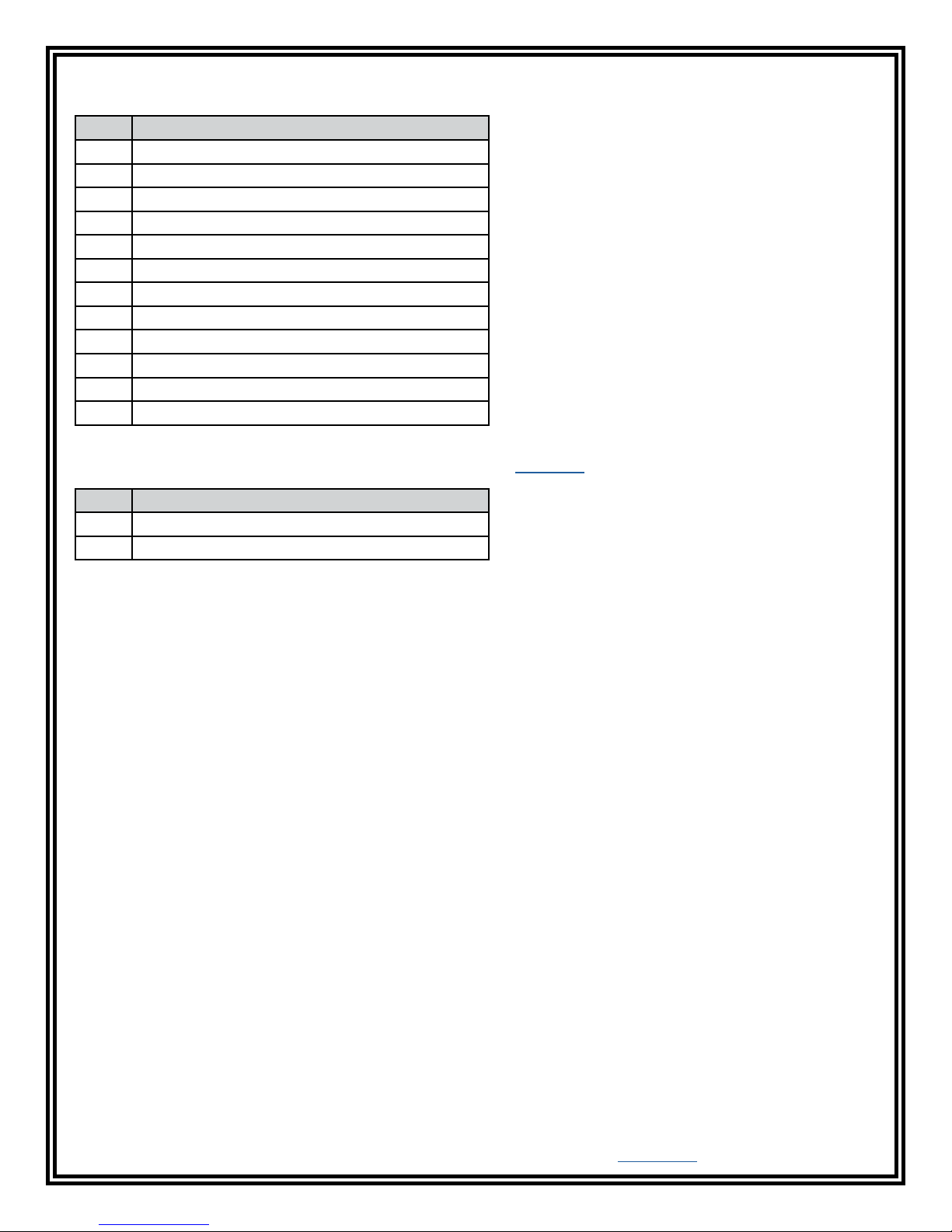
Item Description
50780 SmartLog Pro®
50781 SmartLog Pro® with Turnstile, 120VAC
50782 SmartLog Pro® with Turnstile, 220VAC
50415 Stand
50783 Turnstile Mounting Kit
50755 ESD Glove Test Fixture
50424 Limit Comparator for Testers
50784 5-Pound Electrode for Limit Comparator
50785 Power Adapter, 5VDC, with interchangeable plugs
50786 Replacement Dual Foot Plate
50787 Replacement Foot Plate Cable
50788 Handheld QR Code Scanner, USB
Use the SmartLog Pro® along with the TEAM5 Software to automate the collection of employee ESD testing. This
software is offered in two tiers: TEAM5 and TEAM5 Enterprise. Click here to view the TEAM5 Comparison Chart.
Item Description
50491 TEAM5 Enterprise Software
50493 TEAM5 Software
Packaging
1 SmartLog Pro®
1 Mounting Bracket
1 Dual Independent Foot Plate
1 Power Adapter, 5VDC 3.0A center positive, with interchangeable plugs (North America, UK/Asia, Europe)
1 Foot Plate Cable, 6.5 feet
1 Ground Cord
1 Thumb Screw
2 Mounting Anchors
2 Mounting Screws
2 Zip Ties
1 Plunger and Spring Assembly for 10mm Wrist Cord Adapter
1 Certificate of Calibration
EMIT - 3651 Walnut Avenue, Chino, CA 91710 • (909) 664-9980 • Website: DescoEMIT.com
TB-6594 Page 4 of 12
© 2018 DESCO INDUSTRIES, INC.
Employee Owned
Page 5
Features and Components
A
B
F
D E
C
G
H
I
J
M
N
K
O
L
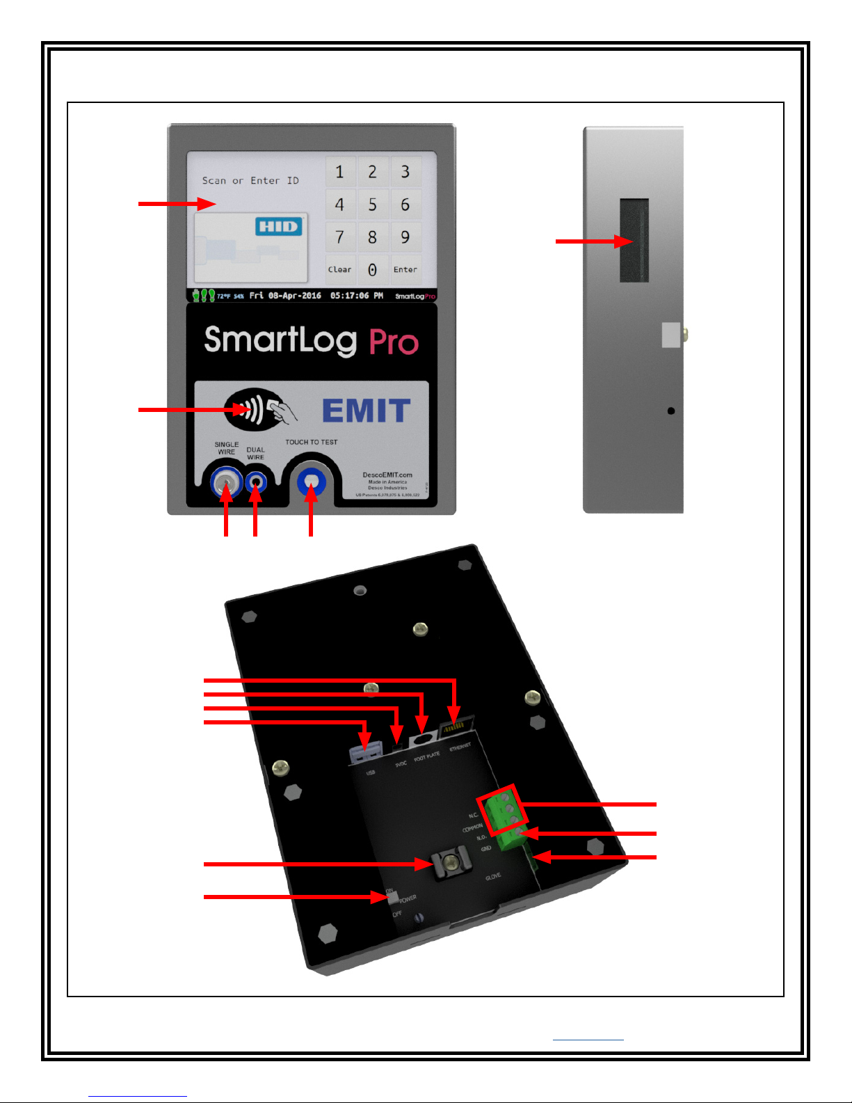
Figure 3. SmartLog Pro® features and components
EMIT - 3651 Walnut Avenue, Chino, CA 91710 • (909) 664-9980 • Website: DescoEMIT.com
TB-6594 Page 5 of 12
© 2018 DESCO INDUSTRIES, INC.
Employee Owned
Page 6
A. Touchscreen Display: Displays the keypad, time,
date, temperature, humidity, command prompts, test
results and settings.
B. Embedded HID OMNIKEY® Proximity Reader:
Users can begin the test by holding a proximity badge
in front of the proximity reader symbol. The HID
OMNIKEY® reader is compatible with the following
badge formats: HID Prox®, Indala Prox, MIFARE®
Classic, MIFARE DESFire® EV1, iCLASS®.
Contact EMIT Customer Service if a different proximity
badge format is to be used.
C. Single-Wire Wrist Strap Jack: Connect the
single-wire wrist cord here to test.
See “10mm Wrist Cord Adapter” on page 7 if using
single-wire wrist cords with a 10mm snap termination.
D. Dual-Wire Wrist Strap Jack: Connect the dual-wire
wrist cord here to test.
Installation
Hardware Setup
If the SmartLog Pro® is located near a restroom, sink or
other water source, operators will need to be instructed
to thoroughly dry their hands before testing. Wet hands
may cause inaccurate test results and damage to the
tester.
1. Connect the ground cord, foot plate cable, Ethernet
cable and power adapter to the SmartLog Pro®.
2. Route all cables through the U-shaped opening
located at the bottom of the SmartLog Pro® and
secure them to the cable tie mount with the included
zip tie.
3. Connect the ground cord’s ring terminal to a
known ground point. Connect the foot plate cable
to the foot plate. Verify that the Ethernet cable is
connected to your network.
E. Solid-State Test Switch: Place and hold your finger
here to begin the test.
F. CCD Barcode Scanner: Reads Code 39 and
128 barcode symbologies by default. Other barcode
symbologies are available upon request.
G. Ethernet Jack: Provides communication to the
SmartLog Pro® over a network. See “Network Setup” on
page 8 for more information.
H. Foot Plate Jack: Connect one end of the foot plate
cable here and the other end to the dual foot plate.
I. 5VDC Power Jack: Connect the included power
adapter here to power the SmartLog Pro®.
J. Dual USB Ports: Used for EMIT certified external
readers and accessories.
K. Cable Tie Mount: Use the included zip ties to
secure all cables and cords connected to the SmartLog
Pro®.
L. Power Switch: Slide the switch to the top position
to turn ON the SmartLog Pro®. Slide the switch to the
bottom position to turn OFF the SmartLog Pro®.
M. Relay Terminal: Integrates with electronic door
locks, lights, buzzers, etc. See “Relay Terminal” on
page 8 for more information.
4. Connect the power adapter to an appropriate power
outlet, and power the SmartLog Pro® by sliding its
power switch to the ON position. The display will
turn on, and the boot sequence will initiate. “Scan
or Enter ID” will display on the SmartLog Pro® after
the boot sequence has completed. The blue LEDs
will continuously cycle around the test switch when
the ESD tester is on standby.
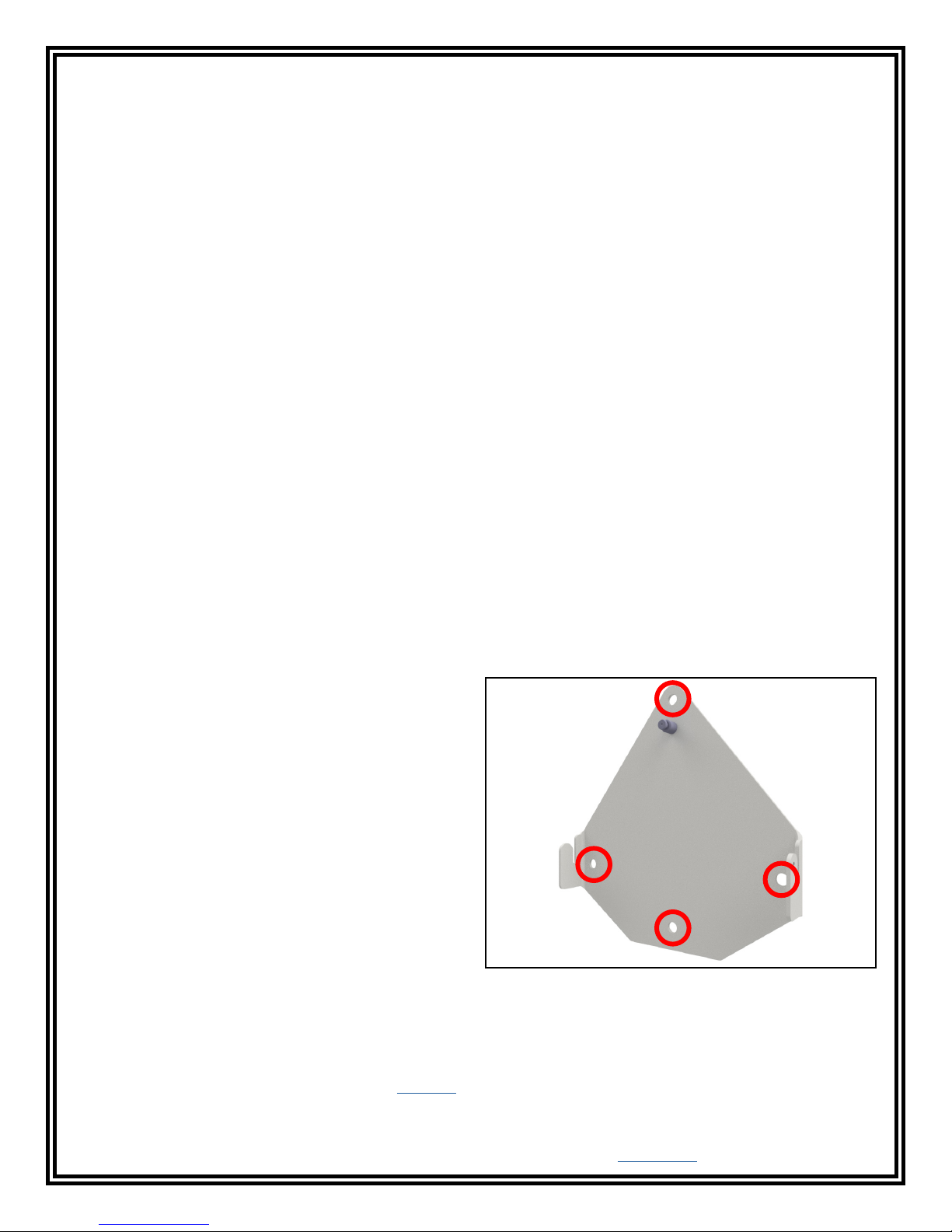
5. Use the included screws and anchors to secure
the mounting bracket to the desired location. The
screws may be used in any of the four holes shown
below. Be sure to locate the bracket where users
can read the display and use the tester.
N. Ground Terminal: Secure the tinned wire
termination of the included ground cord to this terminal.
Connect the ring terminal termination of the cord to
equipment ground. This connection will remove any
static charge from the user before the test.
NOTE: Failure to correctly ground the SmartLog Pro®
may result in damage not covered under warranty.
O. ESD Glove Test Fixture Port: Used for connecting
the EMIT 50755 ESD Glove Test Fixture. See TB-6586
for more information.
EMIT - 3651 Walnut Avenue, Chino, CA 91710 • (909) 664-9980 • Website: DescoEMIT.com
TB-6594 Page 6 of 12
Figure 4. Mounting holes on the SmartLog Pro®
mounting bracket
© 2018 DESCO INDUSTRIES, INC.
Employee Owned
Page 7
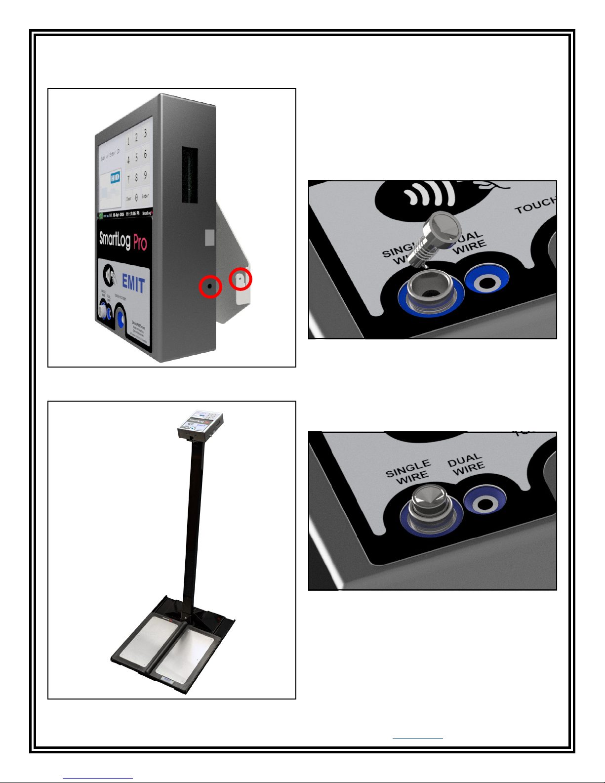
6. Connect the SmartLog Pro® to the bracket. Use the
included thumbscrew to secure the SmartLog as
shown below.
10mm Wrist Cord Adapter
A plunger and spring assembly is included with every
SmartLog Pro®. Use this assembly to retrofit the
single-wire jack on the SmartLog Pro® to test wrist
cords with a 10mm termination instead of a banana
plug. NOTE: This assembly cannot be removed once
installed.
1. Insert the plunger assembly into the single-wire
jack on the face of the SmartLog Pro®. Be sure to
clear the clip at the base of the plunger’s shaft when
inserting into the jack.
Figure 5. Securing the SmartLog Pro® to the mounting
bracket
Figure 7. Inserting the plunger and spring assembly into
the single-wire jack
2. The plunger will slightly protrude out of the
single-wire jack when installed. Test its installation
by pushing down on the plunger. It should dip and
then spring back up when released.
Figure 8. Completed installation of the plunger and
spring assembly
Figure 6. Use the EMIT 50415 SmartLog Stand as a
mounting alternative
EMIT - 3651 Walnut Avenue, Chino, CA 91710 • (909) 664-9980 • Website: DescoEMIT.com
TB-6594 Page 7 of 12
© 2018 DESCO INDUSTRIES, INC.
Employee Owned
Page 8
Relay Terminal
The SmartLog Pro® features a relay terminal that can
be integrated with electronic door locks, lights, buzzers,
etc. to control access to an area.
The relay open and close (activation) time may be
modified using the TEAM5 Software. See the TEAM5
User Manual for more information.
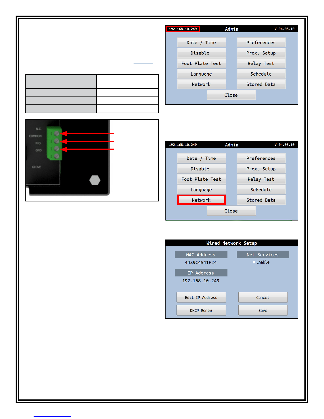
Contact Rating 1A @ 30VDC, .5A @
125VAC
Maximum Switching Power 30W
Maximum Switching Voltage 250VAC, 220VDC
Maximum Switching Current 1A
Normally Closed
Common
Normally Open
Figure 10. Locating the IP address in the Admin Menu
7. Tap the Network button to access the Wired
Network Setup Menu. This menu will allow you to
view and edit any network settings if desired.
Figure 9. Relay terminal contacts located on the back of
the SmartLog Pro®
Network Setup
The following procedures will outline how to connect the
SmartLog Pro® to a local area network (LAN) using its
Ethernet communication module.
DYNAMIC IP PROCEDURE
1. Verify that the Ethernet cable is securely connected
to your network and SmartLog Pro®. The LEDs on
the Ethernet port will illuminate when a connection
to the network is established.
2. The SmartLog Pro® will automatically obtain an IP
address from the DHCP server. The IP address can
be located within the Admin Menu.
3. To access the Admin Menu, tap 0 then Enter on the
touchscreen keypad.
4. The SmartLog will prompt for the Admin ID. Tap 0
then Enter.
5. The SmartLog will prompt for the Admin PIN. Tap 0
then Enter.
6. The Admin Menu will appear. The IP address
can be found in the top left corner. Take note
of this address as it will be required to establish
communication between the SmartLog Pro® and the
TEAM5 Server Software.
Figure 11. Locating the Network button in the Admin
Menu
Figure 12. Wired Network Setup menu
EMIT - 3651 Walnut Avenue, Chino, CA 91710 • (909) 664-9980 • Website: DescoEMIT.com
TB-6594 Page 8 of 12
© 2018 DESCO INDUSTRIES, INC.
Employee Owned
Page 9
STATIC IP PROCEDURE
1. Share the MAC address of the SmartLog Pro®
with an IT administrator, so a static IP address
can be assigned to the unit. The MAC address
can be found on a label applied to the back of the
SmartLog Pro®.
2. Use an Ethernet cable to connect the SmartLog
Pro® to your network. Power the SmartLog Pro®.
3. The SmartLog Pro® will communicate with the
network server and receive the static IP address
assigned by the IT administrator. The IP address
can be located within the Admin Menu.
4. To access the Admin Menu, tap 0 then Enter on the
touchscreen keypad.
5. The SmartLog will prompt for the Admin ID. Tap 0
then Enter.
6. The SmartLog will prompt for the Admin PIN. Tap 0
then Enter.
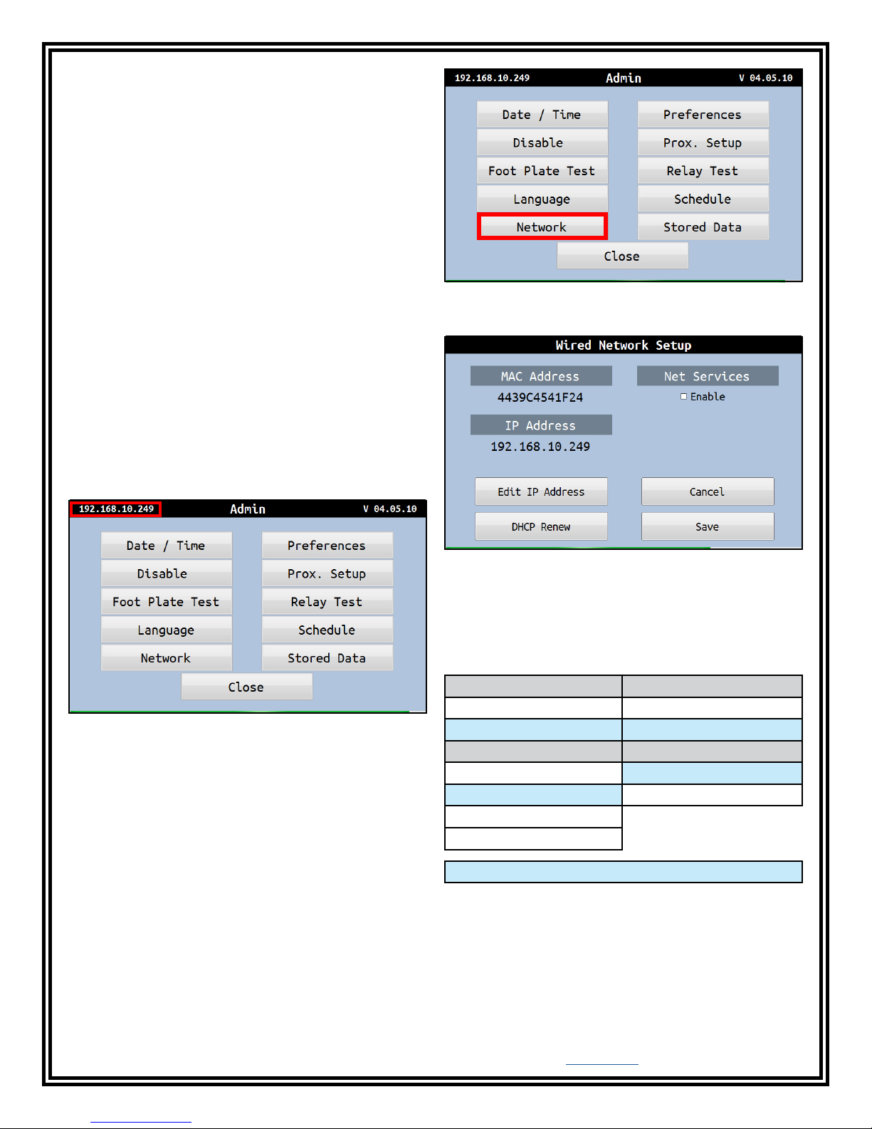
7. The Admin Menu will appear. The IP address
can be found in the top left corner. Take note
of this address as it will be required to establish
communication between the SmartLog Pro® and the
TEAM5 Server Software.
Figure 13. Locating the IP address in the Admin Menu
8. Tap the Network button to access the Wired
Network Setup Menu. This menu will allow you to
view and edit any network settings if desired.
Figure 14. Locating the Network button in the Admin
Menu
Figure 15. Wired Network Setup menu
Test Limit Configuration
The following footwear and wrist strap resistance limits
are available in the SmartLog Pro®:
Footwear Wrist Strap
LOW Limit Resistance LOW Limit Resistance
100 Kilohms (1.0 x 10
750 Kilohms (7.5 x 10
HIGH Limit Resistance HIGH Limit Resistance
10 Megohms (1.0 x 10
35 Megohms (3.5 x 10
100 Megohms (1.0 x 10
1 Gigohm (1.0 x 10
5
) 100 Kilohms (1.0 x 10⁵)
5
) 750 Kilohms (7.5 x 10⁵)
7
) 10 Megohms (1.0 x 10⁷)
7
) 35 Megohms (3.5 x 10⁷)
8
)
9
)**
EMIT - 3651 Walnut Avenue, Chino, CA 91710 • (909) 664-9980 • Website: DescoEMIT.com
TB-6594 Page 9 of 12
Default Settings
**A dirty foot plate could result in a false pass when the
footwear limit is set to 1 Gigohm. Be sure to keep the
foot plate clean with 99% isopropyl alcohol when using
this setting. This setting is not recommended for relative
humidity greater than 50%.
© 2018 DESCO INDUSTRIES, INC.
Employee Owned
Page 10
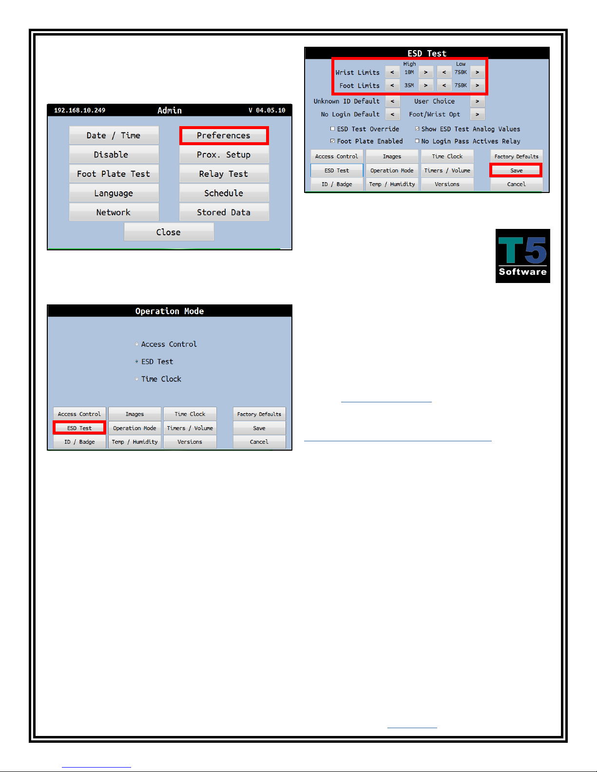
SETTING THE RESISTANCE LIMITS
1. Access the Administrator Menu by entering an
administrator ID number and PIN on the keypad.
2. Tap the Preferences button.
Figure 16. Locating the Preferences button in the Admin
Menu
3. Tap the ESD Test button.
Figure 18. Locating the Wrist and Foot Limits in the
ESD Test Menu
TEAM5 Software
When used with the EMIT SmartLog™,
TEAM5 allows manufacturers and
assemblers to automate the collection
of employee ESD testing. It has a set of
robust employee management functions
that allows automated tracking of employee leave time,
shift and department assignments and ESD training.
TEAM5 connects your ESD test data to the rest of your
manufacturing environment with automated electronic
data interchange in a variety of formats.
Figure 17. Locating the ESD Test button in the
Preferences Menu
4. Adjust the Wrist Strap and Footwear Limits by
tapping the < and > buttons. Tap the Save button
when complete.
TEAM5 Software is required for every SmartLog system
installation. TEAM5 is compatible with the SmartLog
V5™ and SmartLog Pro® systems.
See the TEAM5 User Manual for more information.
The software may be downloaded using the following
link:
http://emit.descoindustries.com/team5.aspx
NOTE: A license dongle is required to run the software.
Contact EMIT Customer Service to schedule an
installation session.
EMIT - 3651 Walnut Avenue, Chino, CA 91710 • (909) 664-9980 • Website: DescoEMIT.com
TB-6594 Page 10 of 12
© 2018 DESCO INDUSTRIES, INC.
Employee Owned
Page 11
Operation
NOTE: The SmartLog Pro® must first be programmed
with the user ID table using the TEAM5 Software before
being deployed for employee use, or the default test
settings will be applied.
See the TEAM5 User Manual for more information.
If the SmartLog Pro® is located near a restroom, sink or
other water source, operators will need to be instructed
to thoroughly dry their hands before testing. Wet hands
may cause inaccurate test results and damage to the
tester.
1. A circling light around the test switch indicates when
the SmartLog Pro® is on standby and ready to
perform a test.
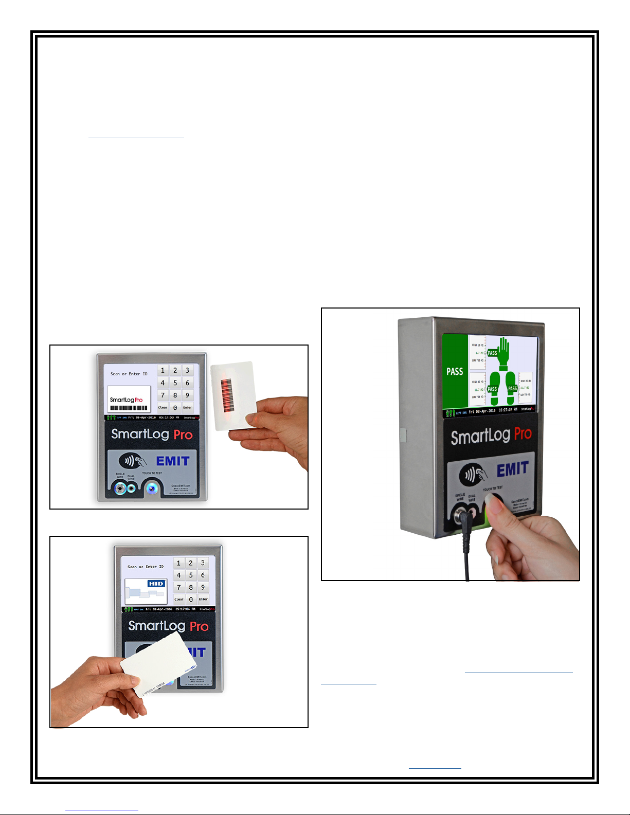
2. Initiate the test procedure by identifying yourself to
the SmartLog Pro®. This may be done using the
touchscreen keypad, barcode scanner or proximity
reader.
NOTE: Hold the proximity badge in front of the RFID
icon for a full second if using proximity badges. See
Figure 20.
3. Follow the prompt on the SmartLog’s display.
4. When performing a footwear test, be sure to place
both feet on the dual foot plate (one foot per plate).
NOTE: Keep the foot plate clean with 99% isopropyl
alcohol when using the 1 Gigohm high test limit. A
dirty foot plate could yield a false pass.
When performing a wrist strap* test, be sure to
completely plug in the wrist cord into the tester’s
jack.
5. To begin the test, use your finger to bridge the test
switch’s inner and outer contacts. The blue standby
LED will become solid to indicate that the test has
been initiated. Hold your finger down until the test
results are displayed on the touchscreen.
If your finger is removed too early, the tester’s blue
LEDs will blink three times to indicate that the test
was not completed. DO NOT touch any other metal
while performing your test as this will affect your
results.
Figure 19. Using the barcode scanner
Figure 20. Holding a proximity badge in front of the
RFID icon on the SmartLog Pro®
EMIT - 3651 Walnut Avenue, Chino, CA 91710 • (909) 664-9980 • Website: DescoEMIT.com
TB-6594 Page 11 of 12
Figure 21. Performing a test with the SmartLog Pro®
6. The relay terminal will activate if the defined tests
are passed (if applicable).
NOTE: Failures may be caused by dry skin or minimal
sweat layer. For wrist straps, try using an approved
dissipative hand lotion such as Menda Reztore™ ESD
Hand Lotion prior to use. Footwear test results can be
improved by taking a short walk to build a sweat layer
for better conductivity.
*The SmartLog Pro® may also be used to test smocks
or garments that feature a grounding mechanism for
operators using a coiled cord connection.
© 2018 DESCO INDUSTRIES, INC.
Employee Owned
Page 12
Maintenance
Specifications
To maintain optimum performance, cleaning should
be performed on a regular basis. Use 99% isopropyl
alcohol to clean the foot plate and test switch. Other
cleaners are susceptible to leaving residue on these
surfaces.
NOTE: Avoid wetting or mopping the foot plate. This
may yield false test results and cause damage to its
internal circuitry.
Calibration
Frequency of recalibration should be based on the
critical nature of those ESD sensitive items handled and
the risk of failure for the ESD protective equipment and
materials. In general, EMIT recommends that calibration
be performed annually.
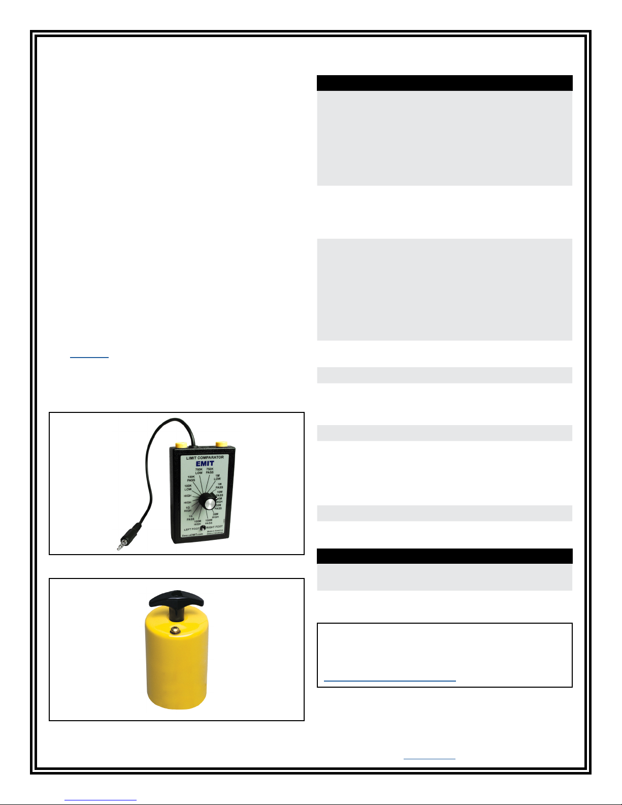
Use the EMIT 50424 Limit Comparator and EMIT 50784
5-Pound Electrode to perform periodic verification (once
every 6-12 months) of the SmartLog Pro®. The Limit
Comparator can be used to check the test limits of the
SmartLog Pro® without removing it from the factory
floor.
See TB-6581 for more information.
NOTE: Calibration is not required for the temperature
and humidity sensor embedded within the SmartLog
Pro®.
SmartLog Pro
Input Voltage and
Frequency
(External Adapter)
®
AC/DC Power Adapter
Power Input:
100-240VAC, 50/60 Hz
Power Output:
5VDC, 3.0A
Cable Length:
5 ft. (1.5 m)
Operating Temperature 70°F to 85°F (21°C to 30°C)
for 1 gigohm test limit
41°F to 85°F (5°C to 30°C)
for all other test limits
Environmental
Requirements
Indoor use only at altitudes
less than 6500 ft. (2 km)
Maximum relative humidity
of 80% up to 85°F (30°C)
decreasing linearly to 50% @
85°F (30°C)
Maximum relative humidity of
50% at 1 gigohm setting
Dimensions 6.75" x 5.00" x 1.75"
(17.1 cm x 12.7 cm x 4.4 cm)
Weight 1.8 lbs (0.8 kg)
Test Accuracy ±20% for 1 gigohm footwear
test limit
±10% for all other test limits
Test Switch Voltage 5 VDC @ open circuit
Wrist Strap and
Footwear Test Voltage
30 VDC @ open circuit
Test current is limited by
resistors and varies on
the test range setting (100
kilohms - 1 gigohm)
Temperature Accuracy ±0.5°C
Humidity Accuracy ±5%
Figure 22. EMIT 50424 Limit Comparator
Figure 23. EMIT 50784 5-Pound Electrode for Limit
Comparator
EMIT - 3651 Walnut Avenue, Chino, CA 91710 • (909) 664-9980 • Website: DescoEMIT.com
TB-6594 Page 12 of 12
Dual Independent Foot Plate
Dimensions 14.0" x 16.0" x 0.9"
(35.6 cm x 40.1 cm x 2.3 cm)
Weight 7.5 lbs (3.4 kg)
Limited Warranty, Warranty Exclusions, Limit of
Liability and RMA Request Instructions
See the EMIT Warranty -
DescoEMIT.com/Warranty.aspx
© 2018 DESCO INDUSTRIES, INC.
Employee Owned
 Loading...