

Page 1
TECHNICAL BULLETIN TB-6512
Monitor Calibration Unit
Installation, Operation and Maintenance
Calibrating the Full Time Continuous Monitor
The Full Time Continuous Monitor is available as the
following item number:
Brand Item
EMIT 50543
EMIT 50544
TESTING THE OPERATOR CIRCUIT
1.
Connect the Calibration Unit’s GROUND test lead to a
ground point.
2. Insert the Calibration Unit’s OPERATOR test lead into
Figure 1. EMIT 50512 Monitor Calibration Unit
Description
The EMIT 50512 Monitor Calibration Unit is designed to
simplify the process of calibrating Workstation Continuous
Monitors. The unit allows the user to quickly and easily
verify whether a tester is operating within specifications. The
Monitor Calibration Unit is a passive device and requires no
power source.
the Full Time Monitor’s OPERATOR jack.
Made in the
United States of America
“A Compliance Verification Plan shall be established
to ensure the Organization’s fulfillment of the technical
requirements of the ESD Control Program Plan (ANSI/
ESD S20.20 section 7.3). The product qualification for the
Continuous Monitors per ANSI/ESD S20.20 Table 3 is “User
defined” test method and required limits, and compliance
verification is per ESD TR53 with the required limit being
“Manufacturer defined.” Per ESD TR53 Compiance
Verification “Compliance verification of the constant monitor
device should follow the manufacturer’s instructions.”
Packaging
1 Monitor Calibration Unit
1 Alligator Clip
1 Stacking Snap Adapter
1 Banana Plug / Wire Adapter
1 Certicate of Calibration
Calibration Test Procedures
The Monitor Calibration Unit was specifically designed for
use in calibration of Desco brand equipment. The following
step by step procedures will cover calibration for specific
test units. The procedures will not cover adjustment of the
test equipment. Contact our Customer Service Department
for detailed information regarding adjustment of specific
continuous monitors.
Figure 2. Connecting the OPERATOR test lead from
the Monitor Calibration Unit to the Full Time Continuous
Monitor
3. Start the Calibration Unit’s selector knob at the full
counter-clockwise position. When testing the operator
circuit, test only the first four limits on the Calibration
Unit. Rotate the selector knob to the LOW FAIL position.
The red OPERATOR GROUND LED on the monitor
should illuminate, and the alarm should sound.
4. Rotate the selector knob clockwise to the LOW LIMIT
position of the green pass sector. The monitor’s green
OPERATOR GROUND LED should illuminate.
TB-6512 Page 1 of 5
January 2014
EMIT - 3651 Walnut Avenue, Chino, CA 91710 • (909) 664-9980 • Website: DescoEMIT.com
© 2014 DESCO INDUSTRIES, INC.
Employee Owned
Page 2
5. Rotate the selector knob clockwise to the HIGH PASS
position at the end of the green pass sector. The
monitor’s green OPERATOR GROUND LED should
remain illuminated.
6. Rotate the selector knob clockwise to the HIGH FAIL
position. The monitor’s red OPERATOR GROUND LED
should illuminate, and the alarm should sound.
7. Disconnect the Monitor Calibration Unit from the monitor.
Calibrating the Dual Operator Continuous
Monitor with Satellites
The Dual Operator Continuous Monitor with Satellites is
available as the following item numbers:
Brand Item
Charleswater 99093
Charleswater 99095
TESTING THE MAT CIRCUIT
1. Connect the Calibration Unit’s GROUND test lead to a
ground point.
2. Insert a wrist cord into the monitor’s operator jack and
snap it to the parking station. This will enable the
audible alarm circuit needed for calbration verfication.
3. Connect the included banana plug / wire adapter to the
Calibration Unit’s MAT test lead. Insert the adapter’s
wire terminal into monitor’s MAT terminal.
TESTING THE OPERATOR CIRCUITS
1. Connect the Calibration Unit’s GROUND test lead to a
ground point.
2. Insert the Calibration Unit’s OPERATOR test lead into
the satellite’s OPERATOR jack.
Figure 4. Connecting the OPERATOR test lead from the
Monitor Calibration Unit to the satellite remote
Figure 3. Connecting the MAT test lead from the Monitor
Calibration Unit to the Full Time Continuous Monitor
4. Rotate the Calibration Unit’s selector knob to the MAT
FAIL 10M position. The monitor’s red MAT GROUND
LED should illuminate, and the alarm should sound.
5. Rotate the selector knob counter-clockwise to the MAT
PASS 10M position. The monitor’s green MAT
GROUND LED should illuminate.
EMIT - 3651 Walnut Avenue, Chino, CA 91710 • (909) 664-9980 • Website: DescoEMIT.com
3. Start the Calibration Unit’s selector knob at the full
counter-clockwise position. When testing the operator
circuit, test only the first four limits on the Calibration
Unit. Rotate the selector knob to the LOW FAIL position.
The corresponding red operator LED on the monitor
should illuminate, and the alarm should sound.
4. Rotate the selector knob clockwise to the LOW LIMIT
position of the green pass sector. The monitor’s
corresponding green operator LED should illuminate.
5. Rotate the selector knob clockwise to the HIGH
PASS position at the end of the green pass sector. The
monitor’s corresponding green operator LED should
remain illuminated.
6. Rotate the selector knob clockwise to the HIGH FAIL
position. The monitor’s corresponding red operator LED
should illuminate, and the alarm should sound.
7. Disconnect the Monitor Calibration Unit from the satellite.
8. Perform the same procedure for the other satellite.
TB-6512 Page 2 of 5
© 2014 DESCO INDUSTRIES, INC.
Employee Owned
Page 3
TESTING THE MAT CIRCUITS
1. Connect the Calibration Unit’s GROUND test lead to a
ground point.
TESTING THE OPERATOR CIRCUIT
1. Connect the Calibration Unit’s GROUND test lead to a
ground point.
2. Insert a wrist cord into the satellite’s operator jack and
snap it to the parking station. This will enable the
audible alarm circuit needed for calbration verfication.
3. Connect the included stacking snap to the Calibration
Unit’s MAT test lead. Disconnect the satellite from
its mat connection and re-install it to the Calibration
Unit’s stacking snap.
NOTE: The stacking snap must be isolated from the
grounded mat.
2. Insert the Calibration Unit’s OPERATOR test lead into
the Jewel® Mini Monitor’s OPERATOR jack.
Figure 6. Connecting the OPERATOR test lead from the
Monitor Calibration Unit to the
Jewel® Workstation
Continuous Mini Monitor
Figure 5. Connecting the MAT test lead from the Monitor
Calibration Unit to the satellite
4. Rotate the Calibration Unit’s selector knob to the MAT
FAIL 10M position. The monitor’s corresponding red mat
LED should illuminate, and the alarm should sound.
5. Rotate the selector knob counter-clockwise to the MAT
PASS 10M position. The monitor’s corresponding green
mat LED should illuminate.
6. Perform the same procedure for the other satellite.
Calibrating the Jewel® Workstation Continuous
Mini Monitor
The Jewel® Workstation Continuous Mini Monitor is available
as the following item number:
Brand Item
Charleswater 99135
3. Start the Calibration Unit’s selector knob at the full
counter-clockwise position. When testing the operator
circuit, test only the first four limits on the Calibration
Unit. Rotate the selector knob to the LOW FAIL position.
The red OPERATOR GROUND LED on the monitor
should illuminate, and the alarm should sound.
4. Rotate the selector knob clockwise to the LOW LIMIT
position of the green pass sector. The monitor’s green
OPERATOR GROUND LED should illuminate.
5. Rotate the selector knob clockwise to the HIGH PASS
position at the end of the green pass sector. The
monitor’s green OPERATOR GROUND LED should
remain illuminated.
6. Rotate the selector knob clockwise to the HIGH FAIL
position. The monitor’s red OPERATOR GROUND LED
should illuminate, and the alarm should sound.
7. Disconnect the Monitor Calibration Unit from the monitor.
TB-6512 Page 3 of 5
EMIT - 3651 Walnut Avenue, Chino, CA 91710 • (909) 664-9980 • Website: DescoEMIT.com
© 2014 DESCO INDUSTRIES, INC.
Employee Owned
Page 4
TESTING THE MAT CIRCUIT
1. Connect the Calibration Unit’s GROUND test lead to a
ground point.
TESTING THE OPERATOR CIRCUIT
1.
Connect the Calibration Unit’s GROUND test lead to a
ground point.
2. Insert a wrist cord into the monitor’s operator jack and
snap it to the parking station. This will enable the
audible alarm circuit needed for calbration verfication.
3. Connect the included stacking snap to the Calibration
Unit’s MAT test lead. Disconnect the monitor from
its mat connection and re-install the snap located
underneath the LEDs to the Calibration Unit’s stacking
snap.
NOTE: The stacking snap must be isolated from the
grounded mat.
BOTTOM VIEW
2. Insert the Calibration Unit’s OPERATOR test lead into
the Multi-Mount Monitor’s operator jack.
Figure 8. Connecting the OPERATOR test lead from the
Monitor Calibration Unit to the
Multi-Mount Continuous
Monitor
Figure 7. Connecting the MAT test lead from the Monitor
Calibration Unit to the
Jewel® Workstation Continuous Mini
Monitor
4. Rotate the Calibration Unit’s selector knob to the MAT
FAIL 500M position. The monitor’s red WORKSURFACE
GROUND LED should illuminate, and the alarm should
sound.
5. Rotate the selector knob counter-clockwise to the MAT
PASS 500M position. The monitor’s green
WORKSURFACE LED should illuminate.
Calibrating the Multi-Mount Continuous Monitor
The Multi-Mount Continuous Monitor is available as the
following item number:
Brand Item
Charleswater 99129
3. Start the Calibration Unit’s selector knob at the full
counter-clockwise position. When testing the operator
circuit, test only the first four limits on the Calibration
Unit. Rotate the selector knob to the LOW FAIL position.
The red OPERATOR GROUND LED on the monitor
should illuminate, and the alarm should sound.
4. Rotate the selector knob clockwise to the LOW LIMIT
position of the green pass sector. The monitor’s green
OPERATOR GROUND LED should illuminate.
5. Rotate the selector knob clockwise to the HIGH PASS
position at the end of the green pass sector. The
monitor’s green OPERATOR GROUND LED should
remain illuminated.
6. Rotate the selector knob clockwise to the HIGH FAIL
position. The monitor’s red OPERATOR GROUND LED
should illuminate, and the alarm should sound.
7. Disconnect the Monitor Calibration Unit from the monitor.
TB-6512 Page 4 of 5
EMIT - 3651 Walnut Avenue, Chino, CA 91710 • (909) 664-9980 • Website: DescoEMIT.com
© 2014 DESCO INDUSTRIES, INC.
Employee Owned
Page 5
TESTING THE MAT CIRCUIT
1. Connect the Calibration Unit’s GROUND test lead to a
ground point.
2. Insert a wrist cord into the monitor’s operator jack and
snap it to the parking station. This will enable the
audible alarm circuit needed for calbration verfication.
3. Connect the included banana plug / wire adapter to the
Calibration Unit’s MAT test lead. Insert the adapter’s
wire terminal into monitor’s MAT terminal.
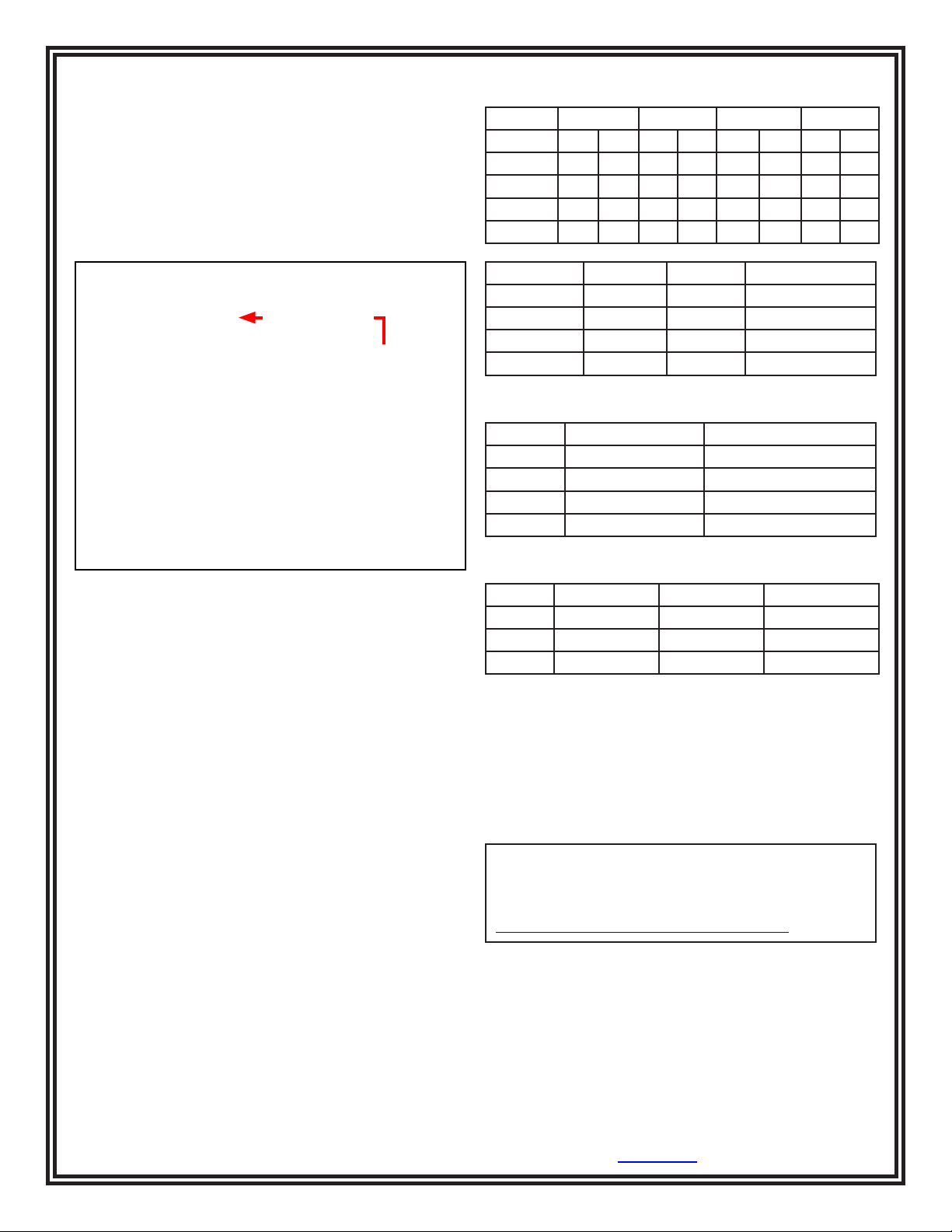
Record Data for:
Low Pass Low Fail High Pass High Fail
Serial # Cp Dis Cp Dis Cp Dis Cp Dis
Serial # Mat Pass Mat Fail Megohms @ 50V
Compare with the following specs (tolerance = ± 10%):
Equiv. Parallel C Dissipation Factor
Low Fail 138.9 pF 0.158
Low Pass 118.6 pF 0.367
Hi Pass 49.0 pF 0.445
Hi Fail 44.7 pF 0.192
Figure 9. Connecting the MAT test lead from the Monitor
Calibration Unit to the
Multi-Mount Continuous Monitor
4. Rotate the Calibration Unit’s selector knob to the MAT
FAIL 10M position. The monitor’s red MAT GROUND
LED should illuminate, and the alarm should sound.
5. Rotate the selector knob counter-clockwise to the MAT
PASS 10M position. The monitor’s green MAT
GROUND LED should illuminate.
Calibration
Required Test Equipment: RLC Bridge
Settings:
For 50 Hz, Frequency = 1,000 Hz (20 x 50), 20th Harmonic
For 60 Hz, Frequency = 1,020 Hz (17 x 60), 17th Harmonic
Set function switch to read “equivalent parallel circuit”
Additional Required Test Equipment for MAT Resistance
Measurement:
Megger: Set V compliance = 50V or less
or
DMM: 50V power supply
Mat (tolerance = ± 4%):
Pass Fail V Measure ~ 50
10 Meg 8 Megohms 12 Megohms
100 Meg 80 Megohms 120 Megohms
500 Meg 400 Megohms 600 Megohms
Specifications
Weight: 6.8 oz
192 g
Dimensions: 4.5" x 2.5" x 1.2"
11.4 cm x 6.4 cm x 3.0 cm
Limited Warranty, Warranty Exclusions, Limit of
Liability and RMA Request Instructions
See EMIT’s Warranty -
http://emit.descoindustries.com/Warranty.aspx
TB-6512 Page 5 of 5
EMIT - 3651 Walnut Avenue, Chino, CA 91710 • (909) 664-9980 • Website: DescoEMIT.com
© 2014 DESCO INDUSTRIES, INC.
Employee Owned
 Loading...