

Eminent Technology LFT-8 Owners manual
EMINENT
TECHNOLOGY
INCORPORATED
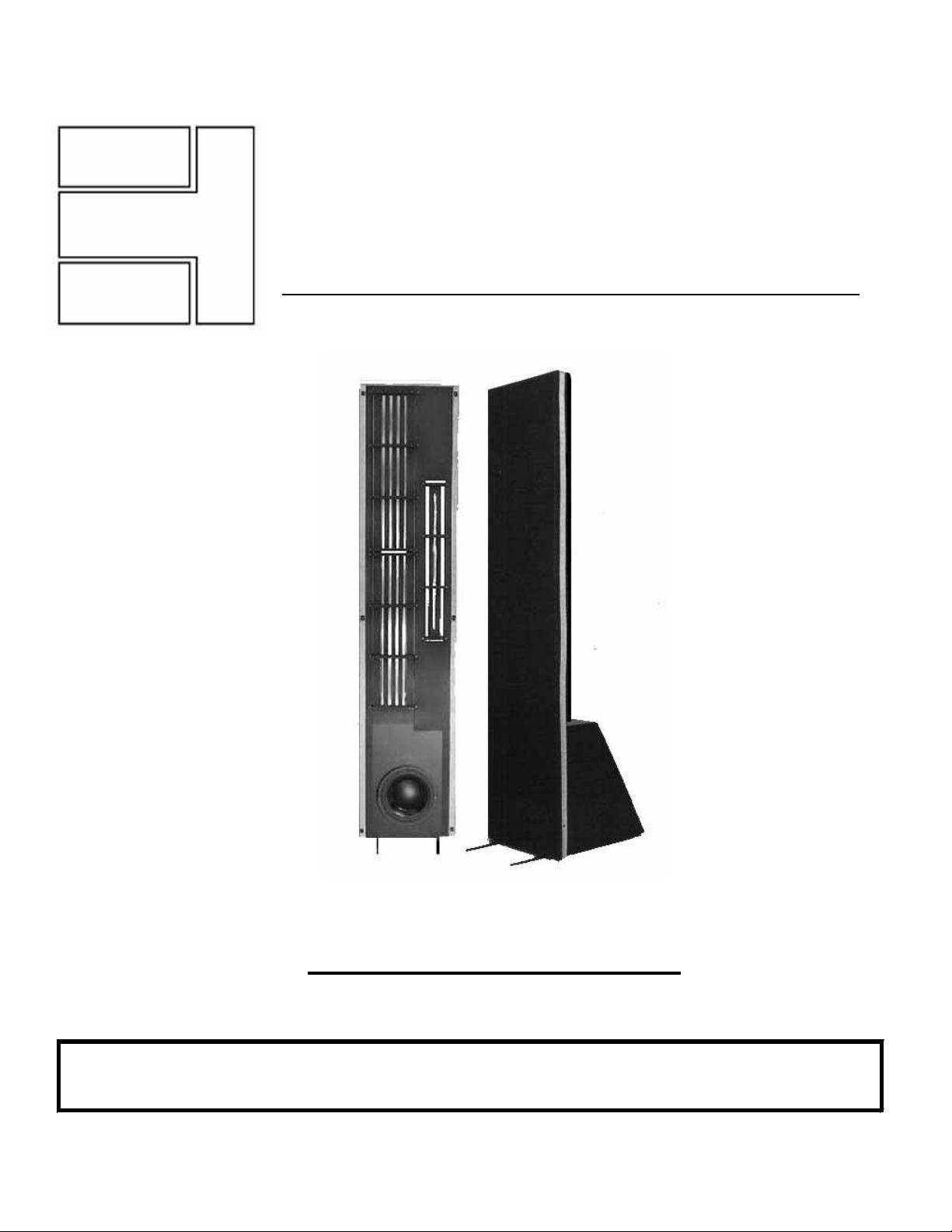
LFT VIII
HYBRID LINEAR FIELD TRANSDUCER LOUDSPEAKER
REFERENCE MANUAL
Revised: 7/22/03
Eminent Technology, Inc. 225 East Palmer Street Tallahassee, Florida 32301
Phone: (850) 575-5655 FAX: (850) 224-5999 Email: info@eminent-tech.com
Website: www.eminent-tech.com

Extremely strong magnetic fields are
present at and around this
loudspeaker. Devices that are
adversely affected by high levels of
magnetic flux, such as television sets
and pacemakers, should be kept at
least three feet away from each
speaker. Also, keep in mind when
any ferrous objects are brought close
to the speakers. Hold steel tools
securely when setting up and
adjusting the LFT-VIII, to prevent a
hex key or screwdriver from slipping
from your hand and damaging the
Mylar diaphragm.
ATTENTION:
STRONG
MAGNETIC
FIELDS
_____________
2

TABLE OF CONTENTS
Installation of the LFT-VIII........................................................5
Unpacking the Speakers.............................................................5
Speaker Assembly......................................................................6
Positioning the Speakers in the Listening Room.......................7
Imaging ......................................................................................7
The Tweeter Level Control ........................................................8
Amplifier Requirements.............................................................8
Bi-Wiring and Bi-Amping.........................................................9
Bi-Amping .................................................................................9
Technical Description................................................................10
Electrostatic Loudspeakers ......................................................11
Planar Magnetic Loudspeakers................................................12
Ribbon Loudspeakers...............................................................13
Evaluating Earlier Approaches................................................14
Electrostatics............................................................................14
Planar Magnetics......................................................................14
Ribbons ....................................................................................14
The Linear Field Transducer....................................................16
Diaphragm Construction..........................................................16
The Magnet/Frame Structure...................................................16
Panel Frequencies ....................................................................18
General Specifications...............................................................19
LFT-VIII Impedance Curve.....................................................20
LFT-VIII Impedance Data........................................................21
Crossover Information..............................................................22
Square Wave Performance ......................................................23
Frequency Response Curve.......................................................24
LFT-VIII Panel Specifications..................................................25
Mid Range Panel Design...........................................................26
LFT-VIII Woofer Specifications..............................................27
Additional Woofer Specifications .............................................28
3

Woofer Design............................................................................29
Woofer Enclosure......................................................................30
Warranty....................................................................................31
Appendix A – Hex Cam Spacer Installation...........................33
Appendix B – Tweeter Diaphragm Replacement...................36
4
A complete technical description of the LFT-VIII is included in this
manual and begins on page 10. It is recommended that you become
familiar with this information because an understanding of the LFT
principals will assist you in the proper set up of these loudspeakers.
Installation of
the LFT-VIII
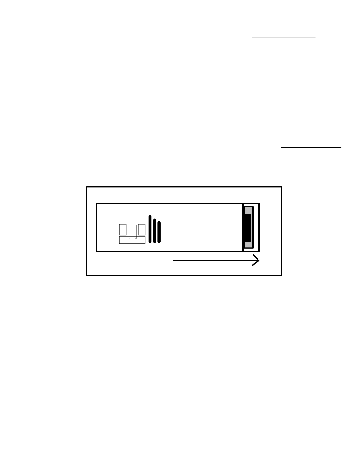
The LFT-VIII is shipped in 3 boxes. The larger square box contains the two
woofer cabinets. The 2 long rectangular boxes contain the panels and grills. To
remove the panels position the box on its side and open the end of the shipping
carton. Remove the padding from the bottom and slide the speaker from the box
as shown below.
Open
Unpacking the
Speakers
After removing the speaker from its carton it can be leaned against a wall
standing up or placed with the front face of the speaker flat on the carpet. Then
the bubble wrap should be removed. The wrap also holds the grill cloth (covered
by a large cardboard sheet) to the speaker. After the wrap is removed these will
separate from the speaker.
Do not attempt to remove or loosen hardware on the drivers themselves.
The magnets are held together under great force and personal injury could
result.
5
Speaker
Assembly
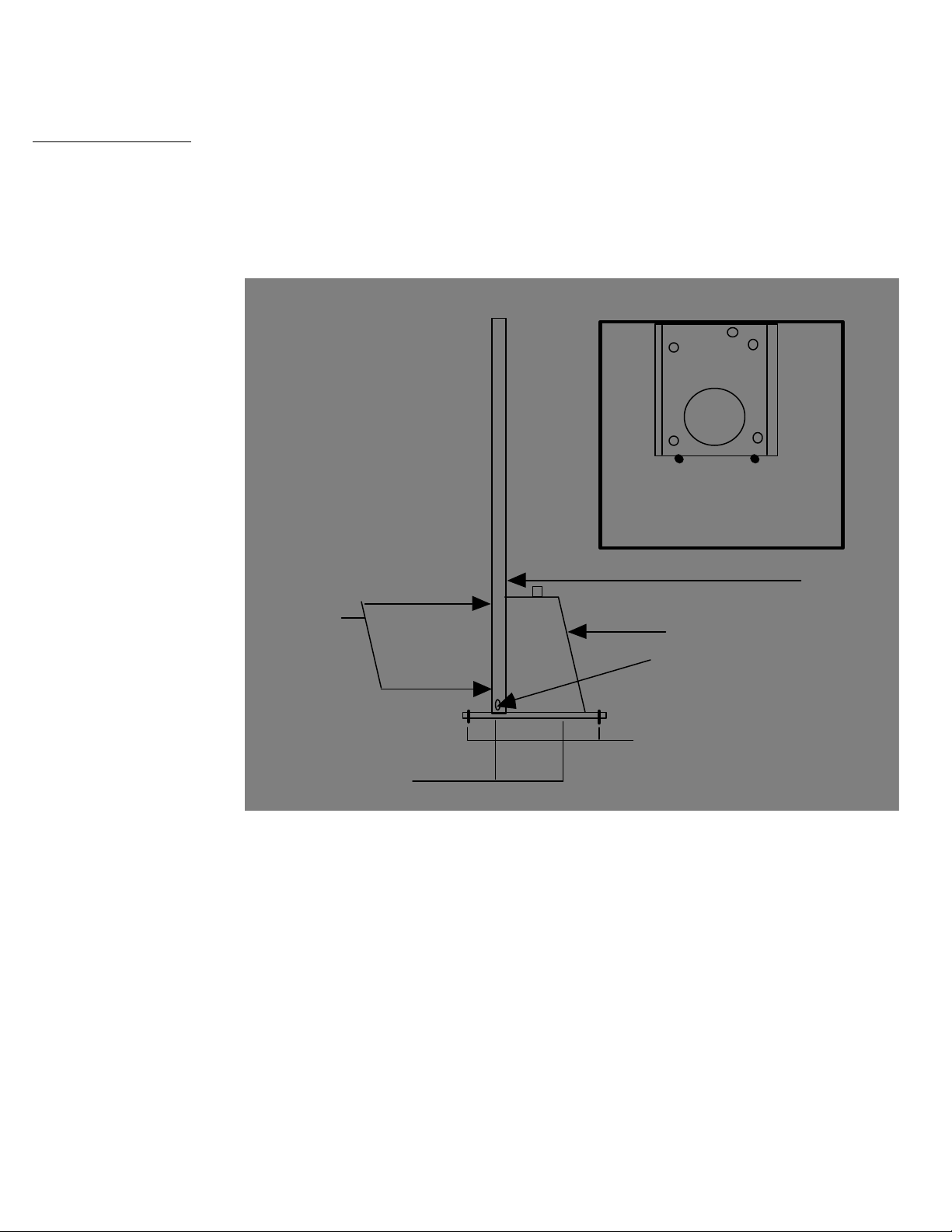
Assemble the panel to each woofer cabinet as shown below.
Fasten the feet to the bottom of the woofer cabinet. Use the
drawing below to identify the correct hardware locations. Grill
cloths snap into place with Velcro fasteners at each corner on the
front and back of the speaker. Bolt the woofer box to the panel as
illustrated below. Laying the speaker on its side may be helpful
in assembly.
Front View Showing
Position of The Five 8X3/4
Sheet Metal Screws
(5) #8X3/4 Sheet Metal
Screws In Front Of Panel
Screws In Bottom
Location Of Terminal Board
Woofer Cabinet
Sheet metal Screw (2)
10-32 x 3/4 Socket Head
Screw (4)(4) #8X3/4 Sheet Metal
Connections to Mid-Range and Tweeter Panels
After attaching the woofer cabinets to the panels, you must attach
the three leads that come out of the mid-range/tweeter panel to the
screw barrier terminals on top of the woofer cabinets. The small
black wire (18 ga.) that comes from the tweeter panel is secured
to on of the terminals marked High, Med or Low on top of the
woofer cabinet. The larger diameter wires (12 ga.) will be
attached to their respective terminals atop the woofer cabinet,
Black to Negative, White to Positive.
6

Speaker placement is critical for correct imaging, frequency
balance, low frequency performance, and efficiency.
The LFT-VIII speakers are a mirror image pair and should be set
up with the tweeter panels to the inside.
Low frequency performance in particular can be determined by
the shape of the room and the speaker's distance from the wall
immediately behind them. Typically, the optimal distance
between the LFT’s and the rear wall is 1 to 5 feet in an average
room.
The overall frequency balance of the LFT-VIII is somewhat
affected by the degree to which the speakers are toed in toward
the central listening position. The on-axis frequency response of
the LFT-VIII is essentially flat, and it is often best to position the
speakers so that the main listening position is about on axis with
each speaker. Slight mid-range frequency balance changes can be
obtained by pointing the speakers slightly away from the listening
position. Adjusting the speakers’ degree of vertical tilt with the
pointed feet can also alter this balance.
Positioning
the Speakers
in the
Listening
Room
Overall imaging depends primarily on the distance separating the
two speakers relative to their distance from the preferred listening
position; it is also affected by the degree of toe-in. We cannot
accurately predict what will work best in your listening room, and
can suggest only that you begin with the drawing on the previous
page as a starting point or general guideline. Keep in mind that
the parameters that affect frequency balance also tend to affect
imaging properties, and vice versa, so it is best to adjust speaker
placement in small increments and to note carefully all of the
changes effected by each shift in position before proceeding
further.
Imaging
7

The Tweeter
Level Control
The high frequency performance of the LFT’s can be tailored with the
tweeter level control. The high frequency performance of the LFT-VIII
is adjusted with the tweeter level control. There are three tweeter level
positions: High, Mid and Low. These levels adjust the tweeter output
in approximately 3 dB increments. It is best to start with the tweeter
level set to Low, position the speakers for the best overall frequency
balance, and then decide if more high frequency energy is needed.
Amplifier
Requirements
The LFT-VIII is wired for 8-ohm operation and is appropriate for use
with most moderately powered tube and solid-state amplifiers. The
efficiency is 84dB with a 2.83-volt drive (1 “8” ohm watt). The
efficiency rating is lower than average. However, the LFT-VIII
radiates a planar wave front, and as such, on axis its apparent efficiency
at the listening position is higher than the numerical rating implies. The
LFT-VIII has a minimum rating of 75 watts per side, tube or solid state.
It can handle “music power” levels (short term burst) of 300 watts or
more with out difficulty. The largest recommended amplifier size for
the LFT-VIII is 200 watts.
The LFT-VIII does not require a high current amplifier. A receiver may
be used if it has sufficient power. Tube amplifiers should be used with
the 8-ohm tap.
8

The LFT-VIII is configured to allow bi-wiring or bi-amping with a
minimum of trouble.
Bi-wiring simply means connecting a single stereo amplifier (or two
mono amps) to a pair of speakers by using two pairs of speaker cables.
Connect the hot and ground conductors of a pair of cables to the same
output terminals on one channel of the amplifier; the other ends are
connected to the separate woofer and mid/tweeter inputs of the LFTVII (All speaker cables should be the same length). The effects of biwiring tend to be subtle; the slight improvement may be worth the
relatively modest cost of an extra pair or speaker cables. Bi-wiring also
permits experimenting with different types of cables for the two inputs;
you may find that one type is best suited for bass performance, while
another works best on the mid/treble side.
Bi-Wiring and BiAmping
Bi-amping requires and additional stereo amplifier or pair of mono
amps. You will also need some means of insuring that only the desired
portion of the frequency range reaches each amplifier. The simplest
way to accomplish this is with an external electronic crossover;
however, this can also be done by hard-wiring low-pass and high-pass
filters into the inputs of the bass/mid and treble amplifiers, respectively.
For the low/ frequency amp, a 180Hz low-pass filter (6 dB/octave) is
required; for the mid/treble amp, a 180Hz. high-pass filter (also 6
dB/octave) is required. If you wish to pursue this method, your dealer
or the manufacturer of your amplifiers should be able to help you
determine the specific parts necessary. Note that you will also need a
level control on either one of the stereo amps or on the crossover,
regardless of which approach you take to bi-amping. Contact Eminent
Technology or refer to the schematic in the back of this manual to
modify the crossover for proper speaker operation.
9
Bi-Amping

Technical
Description
The Eminent Technology Linear Field
Transducer is a full-range, push-pull, dynamic
planar loudspeaker. In a sense, it is the
magnetic equivalent of a push-pull electrostatic
loudspeaker, differing in that it requires no
step-up transformer or bias voltage, and that
the audio signal is applied directly to its
diaphragm.
The LFT-VIII
To fully understand the strengths of the LFT design, one must
first consider the design and operation of this speaker's three most
notable antecedents: the push-pull electrostatic loudspeaker
(ESL); the traditional, single-ended planar magnetic loudspeaker,
and the ribbon loudspeaker.
10
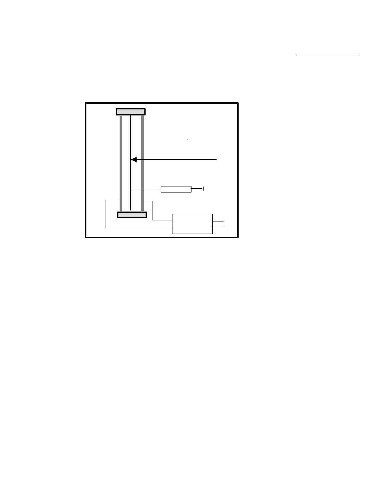
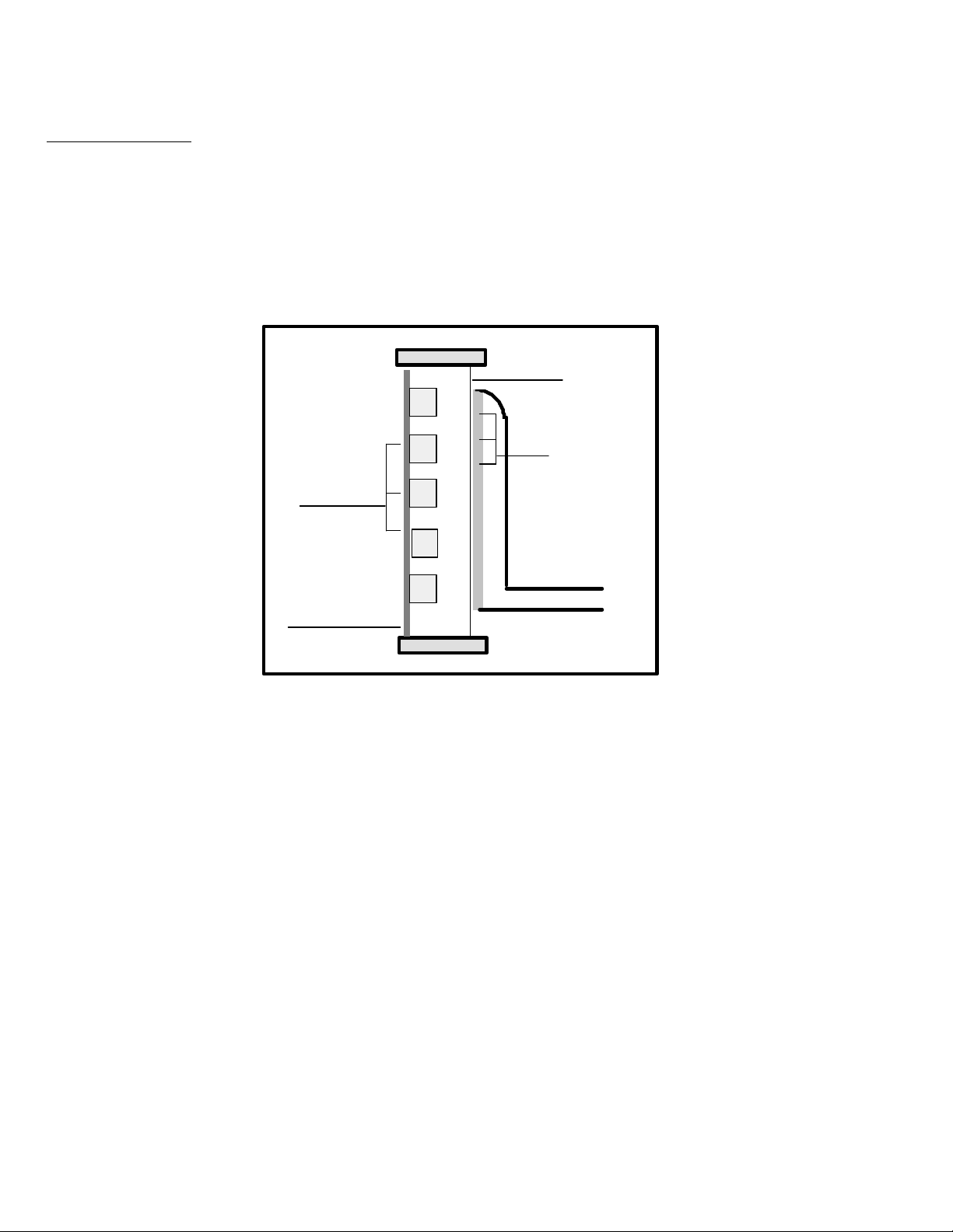
The electrostatic starts with a very thin (half mil or less)
diaphragm made of Mylar or a similar material, to which a light
coating of mildly conductive substance such as graphite has been
applied. This diaphragm is suspended on a rigid frame and
sandwiched between two stationary conductive grids (usually
perforated metal plates) called stators.
FRAME
FRONT
STATOR
REAR STATOR
[PERFORATED
METAL PLATE]
RESISTOR
TRANSFORMER
CONDUCTIVE
DIAPHRAM
TO BIAS
VOLTAGE
SUPPLY
TO
AMPLIFIER
-+
Electrostatic
Loudspeakers
A DC charge of high voltage (in the thousands of volts) but very
low current, known as the bias voltage, is applied to the
conductive diaphragm and kept constant. A step-up transformer
is introduced to increase the usable voltage of the amplifier's
output (while simultaneously decreasing the current), and the two
ends of the transformer's output coil are connected to the two
stators.
As the amplifier produces a continuously varying AC voltage,
(the amplified music signal), the charge on the two stators will
also continuously change in synchronization with the music; and
since the two stators are connected to two different ends of the
transformer's output, one stator will take on a predominantly
negative charge at the same time and to the same extent that the
other stator takes on a predominantly positive charge. The
constant-charge diaphragm will thus undergo a continuously
changing state of attraction to and repulsion from the two stators
as their polarization changes, and it is this motion that excites the
air to the front and rear of the speaker and produces sound.
11
Planar Magnetic
Loudspeakers
The traditional planar magnetic also starts with a thin Mylar
diaphragm, one side of which is coated with adhesive and fitted
with an aluminum wire voice grid, (analogous to the voice coil of
a conventional cone driver). The diaphragm is held taut in a
metal frame. On the front of this frame is a large sheet of
perforated metal, to which rows of vertically aligned strip
magnets have been fastened.
FRAME
DIAPHRAM
S
VOICE GRID
[ACTUALLY A
PERMANENT
STRIP
MAGNETS
N
S
N
CONTINUIOS LOOP]
PERFORATED
METAL
SHEET
S
TO AMPLIFIER
+
SINGLE-ENDED PLANAR MAGNETIC
[TOP VIEW CROSS-SECTION]
Spacing exaggerated to show detail
From there, the operation of a single-ended planar magnetic
loudspeaker is remarkably similar to that of a conventional cone
driver: The amplifier's output is sent directly through the voice
grid and, because it is suspended within a stationary magnetic
field, the grid moves back and forth within that field in
synchronization with the AC voltage that is the amplified music
signal. Since the voice grid is permanently fastened to a taut
diaphragm, the diaphragm also moves in synchronization with the
music signal, exciting the air and producing sound.
12
 Loading...