

EMI WLHG09, WLHG24, WLHG12 Installation, Operation And Maintenance Manual

WLCG/WLHG
High-Efciency Ductless Split System High-Wall Air Handlers
Straight cool / Heat pump nominal capacities
WLHG09 WLHG12 WLHG24
Units
9,000 12,000 18,000 23,800 Btuh
2.6 3.5 5.3 7.0 kW
Straight cooling only
WLCG30 WLCG36
Units
28,200
33,600
Btuh
8.3 9.8 kW
Installation, Operation and
Maintenance Manual
ECR International Inc
2201 Dwyer Ave.
Utica, NY 13501
www.enviromaster.com
An ISO 9001-2008 Certified Company
P/N 240008111, Rev. G [06/18/10]
WLCG/WLHG

WLCG/WLHG
High-Wall Air Handlers
• Installation, Operation and Maintenance Manual •
Comfort where it counts 2 P/N 240008111, Rev. G [06/18/10]
Contents
To the Installer
Retain this manual and warranty for
future reference. Before leaving the premises, review this manual to be sure the unit
has been installed correctly and run the
unit for one complete cycle to make sure
it functions properly.
To obtain technical service or warranty
assistance during or aer the installation
of this unit, contact your local representative. For a local representative listing, visit
our web site:
www.enviromaster.com
For further assistance call:
1-800-228-9364
When calling for assistance, please have
the following information ready:
Model Number _____________
Serial Number _____________
Date of installation ___________
IMPORTANT
Shipping damage MUST
be reported to the carrier
IMMEDIATELY.
Examine the exterior. Remove
cover and examine piping for
signs of damage.
NOTICE
The EMI series high efficiency air
handler is backed by EMI and ECR
International is tested, rated, and certied in accordance with AHRI Standard
210/240-2008 and UL-1995.
Due to ongoing product development,
product designs and specications may
change without notice.
Please contact the factory for more
information.
Contents . . . . . . . . . . . . . . . . . . . . . . 2
Read Before Proceeding . . . . . . . . . . . . 3
Verify Unit Before Installing . . . . . . . . . . 4
Piston/Orifice Replacement
(when required). . . . . . . . . . . . . . . . . . 6
Mounting the Unit . . . . . . . . . . . . . . . . 7
Electrical Wiring. . . . . . . . . . . . . . . . . . 9
Refrigerant Piping . . . . . . . . . . . . . . . 14
Refrigerant Processing . . . . . . . . . . . . 17
Reassemble the WLCG/WLHG Cabinet . . 18
Initial Start-Up. . . . . . . . . . . . . . . . . . 19
WLCG/WLHG Controller Overview . . . . . 20
Setting the Controller . . . . . . . . . . . . . 22
Unit-Mounted Controller Operation . . . . 25
Wall Thermostat Operation . . . . . . . . . 29
Controller Features. . . . . . . . . . . . . . . 32
Controller Fault Conditions . . . . . . . . . 33
Maintenance. . . . . . . . . . . . . . . . . . . 34
Troubleshooting . . . . . . . . . . . . . . . . 36
Frequently Asked Questions. . . . . . . . . 40
Specifications and Dimensions . . . . . . . 42
WLCG/WLHG System Options . . . . . . . . 44
Test Unit Performance Data Sheet . . . . . 46
EMI’s Product Line . . . . . . . . . . . . . . . 47
Indoor Units . . . . . . . . . . . . . . . . . . . 47
Outdoor Units . . . . . . . . . . . . . . . . . . 47
WLCG/WLHG
High-Wall Air Handlers
• Installation, Operation and Maintenance Manual •
P/N 240008111, Rev. G [06/18/10] 3
Read Before Proceeding
Recognize this symbol as an indication of
important safety information.
WARNING
Completely read all instructions
prior to assembling, installing, operating, or repairing this product.
Inspect all parts for damage prior to
installation and start-up. e EMI series high eciency air handler must be
installed ONLY by qualied installation
personnel.
DANGER
Tampering with this unit is danger-
ous
. Tampering voids all warranties.
DO NOT aempt to modify or change
this unit in any way.
DANGER
e EMI series must:
Be connected to a properly grounded •
electrical supply with the proper
voltage as stated on the rating plate.
Have proper overcurrent protection •
(time-delay fuse/HACR Breaker) as
listed on the rating plate.
Failure to follow these instructions can
result in a re, explosion, or electrical
shock causing property damage, personal
injury, or death.
Safety Instructions
is manual is intended as an aid to qualied service personnel for proper installation, operation, and maintenance of the
EMI series high efficiency air handler.
Read these instructions thoroughly and
carefully before aempting installation or
operation.
Failure to follow these instructions may
result in improper installation, operation,
service, or maintenance, possibly resulting
in re, electrical shock, property damage,
personal injury, or death.
Read all instructions before using this
unit. Install or locate this unit only in accordance with these instructions. Use this
unit only for its intended use as described
in this manual.
Check the rating plate on the unit before
installation to make certain the voltage
shown is the same as the electric supply to
the unit. e rating plate is located on the
top panel only.
This unit must be connected only to a
properly grounded electrical supply. Do
not fail to properly ground this unit.
Turn o the electrical supply before servicing the unit.
Do not use the unit if it has damaged wiring, is not working properly, or has been
damaged or dropped.

WLCG/WLHG
High-Wall Air Handlers
• Installation, Operation and Maintenance Manual •
Comfort where it counts 4 P/N 240008111, Rev. G [06/18/10]
NOTICE
Check equipment for damage prior
to installation, if damaged contact the
wholesale distributor.
Product description
The WLCG/WLHG is available as a •
(DX) direct expansion straight cool or
heat pump.
It offers a contemporary design in a •
ductless type air handler and combines
aractive appearance with high eciency
conditioning for small to medium size
commercial or residential spaces.
The WLCG/WLHG is equipped with •
unit mounted infrared compatible controls which also supports 24V wall thermostat operation. Optional handheld
remote is available.
Heat pump models prov ide up to •
24,000 Btuh of cooling and 20,600 Btuh
of heating. Electric heat options are
available for up to 5 kW of supplemental
heat.
is air handler oers ease of installation, •
operation, and service.
It can be matched with EMI’s:•
Single-zone condensing units –
S1CG/S1HG 09–24 and S1CG
30-36.
Dual-zone condensing units –
S2CH/S2HH side discharge.
Multi-zone, top discharge condens- –
ing units T2CG/T2HG, T3CG/
T3HG, or T4CG/T4HG.
All EMI air handlers are backed by ECR •
International Inc. and are tested, rated,
and certied in accordance with AHRI
standards 210/240-2008 and UL 1995.
Verify Unit Before Installing
Controls and components
(Factory-installed or supplied)
Large LCD Backlit Display•
Single unit-mounted control package, •
congurable to either unit mount or wall
thermostat operation, increasing installation exibility.
NOTICE
Unit mount control — If the control is
congured for unit mount control DO
NOT connect a wall thermostat to the
unit. See Figure 28, Page 22.
Unit mount control can be used in cool-•
ing only, cooling with electric heat, heat
pump, or heat pump with second stage
electric heat applications.
Operational range set point temperature •
adjustable between 55°F(13°C) and 90°F
(32°C)in one-degree increments.
Infrared-compatible controller allows use •
of optional IR hand held controller.
NOTICE
Unit-mounted controls are fully functional without the handheld remote.
Operation modes include Heat, Cool, •
Dry, Fan and Auto Change-over.
Fan Operation – Auto/On. High or Low •
speed fan
Fan Purge – Fan remains on for 60 sec-•
onds aer Heat/Cool call is dropped for
improved eciency (Auto mode only)
Room air sampling Selectable time •
intervals ensure the fan will cycle on periodically, in Auto Fan Mode to help eliminate room temperature stratication.
Selectable Fahrenheit (°F) or Celsius (°C) •
temperature scale.
Dry mode – Operates cooling and electric •
heat simultaneously to remove humidity.
Optional electric heat must be selected.
Anti-Short Cycle Compressor Protec-•
tion.

WLCG/WLHG
High-Wall Air Handlers
• Installation, Operation and Maintenance Manual •
P/N 240008111, Rev. G [06/18/10] 5
Verify Unit Before Installing (continued)
Minimum on time for heating and cooling •
Helps eliminate room temperature droop
and system short cycling.
Freeze Protection – Prevents air handler •
freeze up.
Test operation – Allows ease of testing af-•
ter installation (all timers are reduced).
Non-volatile back-up memory will main-•
tain control seings for an indenite period during a power outage. When power
is restored the equipment will resume
operation aer a three-minute compressor time delay.
7-day programmable with copy feature.•
Filter change indicator: A timer feature •
indicates when the lter should be cleaned
according to the selected time.
Motorized supply louver with optional •
sweep or six stationary seings.
Modular design – reduces parts required •
for control package. Deco panel, relay
board, ribbon cables and microprocessor
are combined into one package.
Integral condensate pump safety-switch •
connection where-by the microprocessor monitors the condensate pump safety
switch and displays an error code when a
fault occurs. (Applies only with optional
condensate pump)
CEC (California Energy Commission) •
compliant
Condensate drain pan over ow protec-•
tion
Cabinet Features:
Durable ABS plastic cabinet with a galva-•
nized steel sub-chassis.
Easily accessible, washable, reusable, •
nylon mesh lter.
Horizontal discharge louver, constructed •
of high temperature ABS plastic, that can
be set to oscillate, or can be parked in six
pre-set positions.
Manually adjustable vertical discharge •
ns.
Easy access to pipe chase area from cabi-•
net boom allows piping connections and
condensate pump installation with the
unit mounted on the wall.
Easily removable end-cap for access to •
control area for installation and service.
Condensate drain pan constructed of gal-•
vanized steel (G90U), with anti-corrosion
coating.
Modular snap-in, 7-day programmable •
control with large backlit LCD display,
a “Change lter” display feature and selectable Fahrenheit (°F), or Celsius (°C)
temperature scale.
Optional Equipment
Condensate pump (eld installed only)•
24V wall thermostat •
Electric heat with automatic reset high •
temperature cutout and redundant high
temperature fuse link (when heat option
is selected, factory installed only)
Hand-held infrared controller.•
Installer Supplied Items
Low voltage wiring (18 AWG minimum •
required)
High voltage power supply wiring•
Mounting screws and fasteners•
Condensate piping•
Refrigerant piping (if not supplied)•
Refrigerant (for interconnect charge)•
WLCG/WLHG
High-Wall Air Handlers
• Installation, Operation and Maintenance Manual •
Comfort where it counts 6 P/N 240008111, Rev. G [06/18/10]
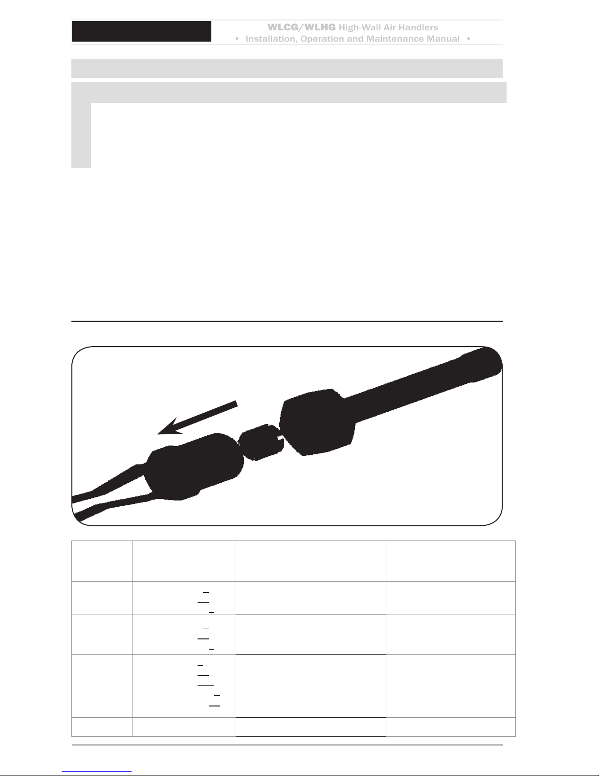
Piston/Orifice Replacement (when required)
NOTICE — WLHG24 ONLY
Piston/ Orifice replacement e factory-installed piston/orice must be replaced on
Air-Handler / Condenser combitnations noted in table below
. All other applications are
to use the factory-installed orice. To replace the orifce in the noted models use instructions and chart as follows.
Replacing the piston/orifice
Follow the instructions on page 9 to remove the le end cap.1.
e piston orice (Figure 1, pg. 6) is located in the upper le corner of the unit.2.
Disassemble the orice joint, remove the factory-installed orice, and replace with the 3.
orice listed in Figure 1 (supplied in the Kit Bag). Make sure o-ring is in good condition
and properly installed.
e end cap can remain o while mounting and installing the unit.4.
Piston/orifice replacementFigure 1
Model Condenser Factory-installed orifice size
(Inches)
Replacement orifice size
(Inches)
WLH_24
T2C/T2HG2400
T2C/T2HG4400
T3C/T3HG2240
0.054” 0.056”
WLH_24
T2C/T2HG9800
T2C/T2HG8800
T3C/T3HG9980
0.054” 0.049”
WLHA12
T2C/T2HG2400
T3C/T3HG2240
T3C/T3HG2220
T4C/T4HG9992
T4C/T4HG9922
T4C/T4HG2222
0.042” 0.044”
WLH_24 S1C/S1HG8000 0.054” 0.047”
To Air
Handler
WLCG/WLHG
High-Wall Air Handlers
• Installation, Operation and Maintenance Manual •
P/N 240008111, Rev. G [06/18/10] 7
Mounting the Unit
Before installing, consider:
Determine the best location for mounting •
the unit for room air circulation.
Locate outdoor and indoor units as close •
together as possible.
Determine how power wire (high and •
low voltage) condensate drainage, and
refrigerant piping may be run to and from
the unit.
WLCG/WLHG - Ensure that intercon-•
nect tubing is within the limits given in
(Table 1, pg. 7)
Tubing specificationsTable 1
S1CG
or
S2CG
Model
Max.
Length
Equivalent
Feet
Max.
Lift
Max.
Trap
Height
Liquid
Line
Suction
Line
“H” “P” O.D. O.D.
09
50’
(15 m)
20’
(6 m)
15’
(5 m)
1/4" 1/2"
12 1/4" 1/2"
18
100’
(30 m)
35’
(11 m)
20’
(6 m)
3/8" 5/8"
24 3/8" 3/4"
30 3/8" 3/4"
36 3/8" 3/4"
To ensure serviceability and proper air •
distribution, the unit should be positioned as close as possible to the center
(left-to-right) of the wall. Minimum
distance from the ceiling is stated on the
template provided with the unit packaging. e cabinet le and right end caps
must be accessible for removal without
obstruction. (See Figure 2, Page 7.)
Site preparation
e WLCG/WLHG must be mounted plumb
and level to a vertical surface to prevent unit
vibration and/or unwanted noise. It is recommended that the unit be mounted directly to a
NOTICE
If excessive noise or vibration is experienced from a unit mounted to a masonry
block wall, check to ensure the unit is
plumb and level. If noise or vibration persists, contact the wholesale distributor.
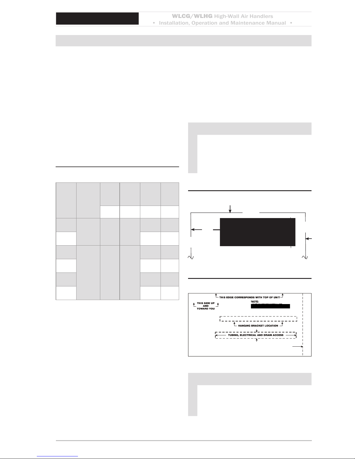
Minimum service clearancesFigure 2
Ceiling
wall
wall
4” Minimum
10”
Minimum
6”
Min.
Mounting templateFigure 3
NOTICE
Piping may be roughed in before wallboard or panels are placed in new construction. PVC pipe (3” or 4” I.D.) may
be used as a pipe chase.
smooth surface such as Sheetrock® wallboard
or similar material. If mounting to a masonry
block wall, there should be a smooth barrier between the unit and the masonry block
surface to absorb any potential vibration and
prevent the formation of condensate on the
wall.
WLCG/WLHG
High-Wall Air Handlers
• Installation, Operation and Maintenance Manual •
Comfort where it counts 8 P/N 240008111, Rev. G [06/18/10]
Mounting the Unit (continued)
Unit Mounting Instructions
Aer determining the best location for 1.
the unit, use the cardboard template
provided in the packaging (Figure 3,
Page 7).
Mark where the piping, electrical wiring 2.
and condensate drain should penetrate
the wall.
Determine the appropriate hole size and 3.
cut through the wall.
Use the supplied wall bracket. For 4.
shipping purposes, the wall bracket is
fastened to the back of the unit.
Secure the bracket to the wall with 5.
the appropriate screws (for wood) or
anchors (for masonry). Ensure the
bracket is mounted in a manner that will
support the weight of the unit (Figure 4,
Page 8).
To mount the unit to the bracket, align 6.
the mounting slot on the back of the
unit over the bracket and make certain
it ts properly (Figure 5, Page 8).
WARNING
Replace all panels aer installation or
servicing. Panels must remain on the
unit at all times while powered and in
operation.
Wall hanging bracketFigure 4
Remove and discard
these screws
NOTICE
e wall hanging bracket is not located
in the center of the unit.
Mounting to wall bracketFigure 5
Mounting
slot
Slot for piping
WLCG/WLHG
High-Wall Air Handlers
• Installation, Operation and Maintenance Manual •
P/N 240008111, Rev. G [06/18/10] 9
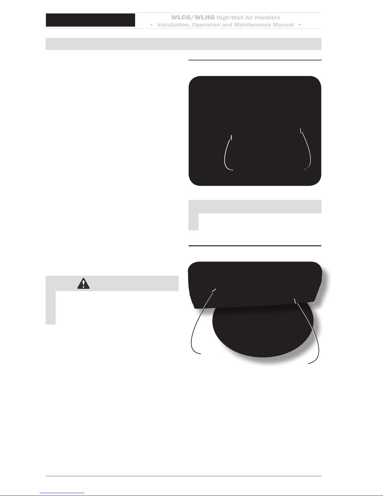
Electrical Wiring
Before removing end capFigure 6
Helpful Tip:
Prior to remov-
ing the end
cap and
bottom
use a
small
board to
prop the unit
away from the wall.
Removing end cap
Figure 7
Rotate louver down to expose Figure 8
screw
NOTICE
All electrical wiring must be run according to NEC and local codes.
Site preparation for wiring
WARNING
Electrical shock hazard Make sure the
power is o before proceeding.
Check the unit rating plate for minimum 1.
circuit ampacity and breaker or time delay
fuse size. Use only HACR type breakers.
Select the proper wire for the ampacity
rating.
Each unit must have a separate branch 2.
circuit protected by a time delay fuse or
breaker. Refer to the unit rating plate for
the proper wire and breaker or time delay
fuse size.
Inspect the existing wiring for any defects 3.
such as cut or frayed wires. Replace if any
such wiring if found.
e le end cap of the unit needs to be 4.
removed to access wiring diagram and
electrical wiring. is requires removal
of three screws (Figure 6, Page 9 and
Figure 7, Page 9).
Rotate louver down to expose the third 5.
screw (Figure 8, Page 9).
Once the screws are removed, slide the 6.
le end cap o to expose control box and
locate the wiring diagram on the inside
of the end cap.
NOTICE
On units rated 208/230V, the primary
side of the transformer is factory wired
for 230V. For a 208V power supply,
the transformer tap must be changed
from orange to red. Refer to the wiring
diagram located on the inside of the le
end cap of the unit.
WLCG/WLHG
High-Wall Air Handlers
• Installation, Operation and Maintenance Manual •
Comfort where it counts 10 P/N 240008111, Rev. G [06/18/10]
Electrical Wiring (continued)
Wiring diagram locationFigure 9
control box
Remove screw
Wiring connectionsFigure 10
Low Voltage
connections
Ground
L1
L2
Connect wiring
To access High and Low volt wiring re-1.
move the screw on the front of the control
box. (Figure 9, pg. 10)
High voltage electrical wiring
Refer to the wiring diagram to connect the 1.
power wire to Black L1 and the other wire
to Red or White (115V) L2 at the power
connector location. (Figure 10, pg. 10)
Connect the ground wire to the ground 2.
lug or lead at the same location in the
control box.
WARNING
Terminate ALL unused wires with a wire
nut or crimp connector.
Low voltage electrical wiring
(for unit-mounted controls)
The 24V control transformer is located 1.
in the air handler. is provides low Volt
control power to both the air handler
and condenser. Depending on the models selected, the low volt interconnect
control wiring may be eected. (Figure
10, pg. 10)
NOTICE
All low voltage interconnect wiring must
be at least 18 AWG.
WLCG/WLHG
High-Wall Air Handlers
• Installation, Operation and Maintenance Manual •
P/N 240008111, Rev. G [06/18/10] 11
Electrical Wiring (continued)
Units with or without heat
NOTICE
All low voltage interconnect wiring must
be at least 18 AWG.
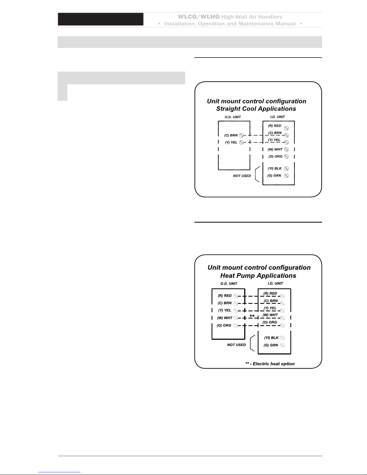
Cooling-only
Cooling only units utilize two low volt interconnecting wires between the indoor and
outdoor units.
Wires designated “Y” (yellow) and “C”
(brown) of the air handler should be connected to the corresponding “Y” (yellow)
and “C” (brown) wires or terminals of the
condenser (Figure 11, Page 11).
Other wires or terminals such as “R” (red) or
“O” (orange) may not be needed and should
be protected by a wire nut from making
contact with the junction box or other metal
surfaces.
Heat pump connection
Heat Pump Connection: In addition to the
“Y” and “C” connections required for cooling,
heat pumps require a reversing valve control
wire “O” (orange) that is energized in the
cooling mode.
If the indoor unit has an electric heater, then
a ”W” (white) wire connection will also be
needed to energize the indoor electric heat.
If a wall thermostat is used.
Heat pumps models require an “R” connection between the indoor and outdoor unit to
provide power to the defrost control board in
the condenser (Figure 12, Page 11).
Unit-mounted controls — Figure 11
cooling only
Unit-mounted controls — Figure 12
heat pump connection, twostage heating
WLCG/WLHG
High-Wall Air Handlers
• Installation, Operation and Maintenance Manual •
Comfort where it counts 12 P/N 240008111, Rev. G [06/18/10]
Electrical Wiring (continued)
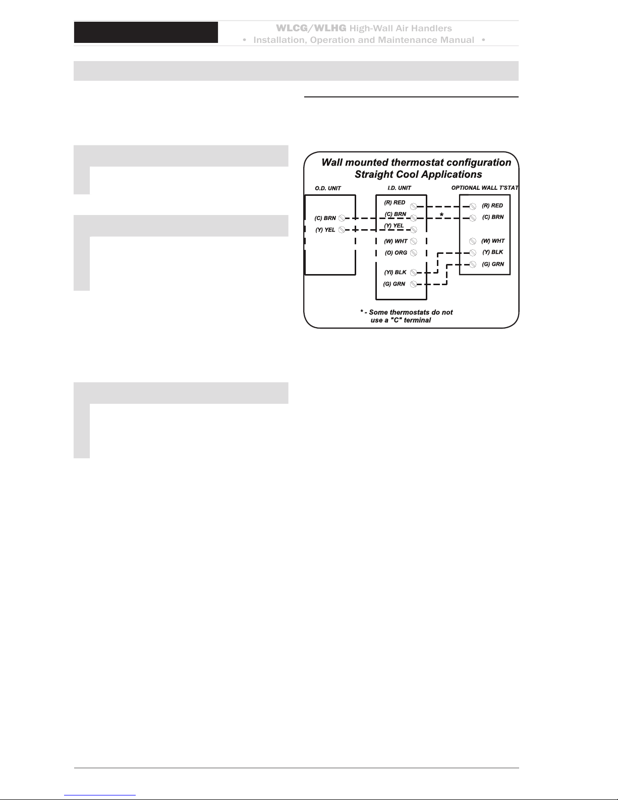
Wall thermostat controls
For remote wall mounted thermostat layout see (Figure 13, pg. 12)
NOTICE
All low voltage interconnect wiring must
be at least 18 AWG.
NOTICE
Unit mount control — If the control
is configured for unit mount control
DO NOT connect a wall thermostat to
the unit.
The 24V control transformer is located in the
air handler unit
. is provides low volt control
power to both the air handler and condenser.
Depending on the models selected, the interconnect control wiring may be eected.
NOTICE
For wall thermostat mode, the key pad
will have limited operation (see Sequence of Operation Wall-mounted
thermostat, page 29).
Choosing a remote wall-mounted
thermostat
See page 29 for wall thermostat selection
information.
Depending on the thermostat required or selected, air handlers may utilize four to six low
volt interconnecting wires between the indoor
unit, thermostat and outdoor unit.
Some thermostats do not require the use of
the “C” (brown) connection. In this case,
ensure that any unused wires are insulated
with a wire nut to prevent them from making
contact with the junction box or other metal
surfaces.
Wall-mounted thermostat Figure 13
configuration —
cooling only

WLCG/WLHG
High-Wall Air Handlers
• Installation, Operation and Maintenance Manual •
P/N 240008111, Rev. G [06/18/10] 13
Electrical Wiring (continued)
Electric heat applications
(Figure 14, Page 13)
If the indoor unit has electric heat then a “W”
connection is required between the thermostat and indoor unit.
Some thermostats do not require the use of
the “C” (brown) connection.
Heat pump applications
(Figure 15, Page 13)
Heat pump operation requires the connection
of the “O” (orange) terminal from the outdoor
unit to the thermostat.
e reversing valve is energized in the cooling mode for EMI models S1HG heat pump
condensers.
NOTICE
Heat pumps only: Two-stage heating
requires the combination of a heat pump
condenser and an indoor unit that is
equipped with an electric strip heater.
e indoor electric heater will energize
as the second stage heat source (the temperature is dependent on the thermostat
selected) and also during the defrost
mode for all heat pump models.
Finishing
Ensure that any unused wires are insulated
with a wire nut to prevent contact with the
junction box or other metal surfaces.
Once certain all electrical connections are
made replace control box cover.
control box
Replace screw
Wall-mounted thermostat Figure 14
configuration —
cooling + electric heat
Wall-mounted thermostat Figure 15
configuration —
cooling + heat pump
WLCG/WLHG
High-Wall Air Handlers
• Installation, Operation and Maintenance Manual •
Comfort where it counts 14 P/N 240008111, Rev. G [06/18/10]
Refrigerant Piping
CAUTION
Avoid piping on wet and rainy days.•
Use only clean, refrigeration-grade •
copper tubing.
Use tubing benders to guard against •
kinking.
Be certain no burrs remain on the •
ings.
Cap ends of lines until ready for con-•
nections. Be certain that plastic end
caps remain in place when inserting
through wall openings.
Insulate the suction line.•
Isolate tubing from transmiing vibra-•
tion to the building or unit and avoid
contact with sharp edges.
Wrap refrigeration valves with a wet •
rag “heat sink” to protect valves while
brazing. (See Figure 14, Page 15.)
DO NOT use a suction line size larger •
than the condenser service valve connection. is can harm the compressor. Install a reducer, when used, only
on the inside connection.
Preparing for piping
With the unit mounted and leveled per 1.
instructions beginning on page 7.
Leave the le end cap o of the unit to 2.
allow removal of the boom panel.
Remove the Phillips-heads screws on the 3.
boom of the unit and remove the boom
panel (Figure 16, Page 14).
See (Figure 17, Page 14) for locations of 4.
the piping connections in the WLCG/
WLHG unit.
Removing bottom panelFigure 16
Piping connections at unitFigure 17
Suction line
(When a reducing bushing is required, install
only here, at the indoor suction-line connection.)
Liquid line
condensate drain
WLCG/WLHG
High-Wall Air Handlers
• Installation, Operation and Maintenance Manual •
P/N 240008111, Rev. G [06/18/10] 15
Refrigerant Piping (continued)
Clean ends of tubingFigure 18
Place wet rag “heat shield” over Figure 19
valves plus a sheet metal shield
to protect paint
Wet rag heat sink
Shield
NOTICE
e WLCG/WLHG is equipped with
a Flo Rater piston expansion device or
TXV. Connections are sweat type.
Line sizing
Size lines per (Table 7, Page 43).1.
e suction line size must match the con-2.
denser service valve connection.
When matching the WLHG24 with a.
an 18,000-Btuh condenser, you must
use a 5/8-inch suction line, with a
reducer installed as shown in (Figure 17, Page 14).
Refrigerant piping
Clean the ends of tubing and insert into 1.
ings (Figure 18 page 15).
Before brazing (Figure 19 page 15):2.
Protect valves by wrapping with a wet a.
rag “heat sink” before brazing.
Use a shield to protect the paint as b.
shown. (e shield can be made from
scrap metal.)
Braze tubing into ings, using a continu-3.
ous nitrogen purge.
e suction line must be insulated the 4.
entire length with closed cell, foam tube
insulation.
Do not insulate the liquid line.5.
Connect the outdoor unit according to 6.
the instructions supplied with unit.
All horizontal piping runs must be level 7.
and without dips to trap the oil.
CAUTION
Pressure test all eld installed piping with nitrogen. Using a suitable vacuum pump,
evacuate the tubing and indoor unit to 500 microns or less, with service valves remaining
front seated (closed).
 Loading...