

EMI S1C, WLHA User Manual
HigH EfficiEncy DuctlEss split systEm
WlcA/WlHA HigH WAll EVApORAtOR
stRAigHt cOOl/HEAt pump*
Nominal Circuit Capacities:
WLHA 9,000, 12,000,
and WLCA (only) 30,000 & 36,000 Btuh
* Heat Pump only available for 9,000-24,000 Btuh units.
18,000, 24,000 Btuh*
Enviromaster International LLC
instAllAtiOn, OpERAtiOn AnD mAintEnAncE mAnuAl
5780 Success Dr.
Rome, NY 13440
www.enviromaster.com
WLCA/WLHA
An ISO 9001-2000 Certied Company
P/N# 240006021 Rev. 1.3 [05/07]

WLCA/WLHA HiGH WALL HiGH EffiCiEnCy EVAporAtor
instALLAtion, opErAtion And mAintEnAnCE mAnUAL
P/N 240006021, Rev. 1.3 [05/07]
This manual is intended as an aid to a qualied service personnel for proper installation,
operation, and maintenance of EMI AmericaSeries high efciency evaporators. Carefully
read these instructions before attempting installation or operation. Failure to follow
these instructions may result in improper installation, operation, service, or maintenance,
possibly resulting in re, electrical shock, property damage, personal injury, or death.
Shipping Damage MUST be Reported to the Carrier IMMEDIA TELY!!!
Examine the carton for signs of damage if any is evident open packaging and
check the unit for shipping damage.
to tHE instALLEr
sAfEty instrUCtions
(1) Retain this manual and warranty for future
reference.
(2) Before leaving the premises, review this
manual to be sure the unit has been
installed correctly and run the unit for
one complete cycle to make sure it
functions properly.
To obtain technical service or warranty
assistance during or after the installation
of this unit, check our website @ www.
enviromaster.com or call your installing
contractor or distributor. Our technical
service department may be contacted at
1-800-228-9364.
When calling for assistance, please have
the following information ready:
• Model Number___________________
• Serial Number___________________
• Date of installation________________
dAnGEr
! !
tampering with the Emi Americaseries evaporator is dangerous
and may result in serious injury or
death. tampering voids all warranties. do not attempt to modify or
change this unit in any way.
Read all instructions before us-
ing the EMI AmericaSeries high
efficiency evaporator. Install or
locate this unit only in accordance
with these instructions. Use this
unit only for its intended use as
described in this manual.
Check the rating plate on the EMI
AmericaSeries evaporator before
installation to make certain the
voltage shown is the same as the
electric supply to the unit.
The EMI AmericaSeries evaporator
must be connected only to a properly
grounded electrical supply. Do not
fail to properly ground this unit.
Turn off the electrical supply before
servicing the EMI AmericaSeries
evaporator.
Do not use the EMI AmericaSeries
evaporator if it has damaged wiring,
is not working properly, or has been
damaged or dropped.
[Save these instructions]
WLCA/WLHA High Wall Evaporator
2
www.enviromaster.com
prodUCt dEsCription
The AmericaSeries WLCA/WLHA is
available as a (Dx) direct expansion straight
cool and heat pump. It offers a contempo-
rary design in a ductless type evaporator and
combines attractive appearance with high
efciency conditioning for small to medium
size commercial or residential spaces. The
WLCA/WLHA is equipped with unit mounted
infrared compatible controls which also sup-
ports 24V remote wall thermostat operation.
Optional hand held remote is available.
Heat Pump models provide up to
23,000 Btuh of cooling and 20,600 Btuh of
heating. Electric heat options are available
for up to 5 kW of supplemental heat.
This American-made evaporator offers
ease of installation, operation, and service.
It can be matched with EMI’s S1CA/S1HA
09-24 and S1CA 30-36 Btuh Single-Zone
Condensing Units, the S2CA side discharge
Dual-Zone Condensing Unit, or the T2CA,
T3CA, and T4CA top discharge Multi-Zone
Condensing Units.
All EMI
Air Handlers are backed by
Enviromaster International LLC and are
tested and rated in accordance with ARI
standards 210/240 and UL 1995.
ControLs And ComponEnts
Note: If the control is congured for
unit mount control do NOT connect
a wall thermostat to the unit.
• Large LCD Backlit Display
• Single unit mounted control pack-
age, congurable to either unit mount
or remote wall thermostat operation,
reducing model number or SKU’s
required.
• Universal control can be used in
cooling only, cooling with electric heat,
heat pump, or heat pump with second
stage electric heat applications.
• Operational range set point tem-
perature adjustable between 55°F and
90°F in one-degree increments.
WLCA/WLHA High Wall Evaporator
ControLs And ComponEnts
Continued
• Infra red compatible control allows
use of optional IR hand held controller.
note: Unit mounted controls are
fully functional without the handheld
remote.
• Operation modes include Heat, Cool,
Dry, Fan and Auto Change-over.
• Fan Operation – Auto/On. High or Low
speed fan
• Fan Purge – Fan remains on for
60 seconds after Heat/Cool call is
dropped for improved efciency (Auto
mode only)
• Room air sampling: Selectable time
intervals ensure the fan will cycle
on periodically, in Auto Fan Mode
to help eliminate room temperature
stratication.
• Selectable Fahrenheit (°F) or Cesius
(°C) temperature scale.
• Dry mode – Operates cooling and
electric heat simultaneously to remove
humidity. Optional electric heat must
be selected.
• Anti-Short Cycle Compressor Protection.
• Minimum on time for heating and
cooling Helps eliminate room temper-
ature drop and system short cycling.
• Freeze Protection – Prevents evapo-
rator freeze up
.
• Test operation – Allows ease of test-
ing after installation (all timers are
eliminated).
• Non-volatile back-up memory will
maintain control settings for an indenite
period during a power outage. When
power is restored the equipment will
resume operation after a three-minute
compressor time delay.
• 7-day programmable with copy feature.
• Filter change indicator: A timer fea-
ture indicates when the lter should be
changed according to the selected time.
• Motorized supply louver with optional
sweep or six stationary settings.
3
www.enviromaster.com
WLCA/WLHA ControLs And ComponEnts
Continued
• Modular design – reduces parts
required for control package. Deco
panel, relay board, ribbon cables and
microprocessor are combined into one
package.
• Integral condensate pump safety-
switch connection where-by the mi-
croprocessor monitors the condensate
pump safety switch and displays an
error code when a fault occurs. (Applies
only with optional condensate pump)
• CEC (California Energy Commission)
compliant
• Condensate drain pan over ow
protection
Cabinet Features:
• Durable ABS plastic cabinet with a
galvanized steel sub-chassis.
• Easily accessible, washable, reusable,
nylon mesh lter.
• Horizontal discharge louver, construct-
ed of high temperature ABS plastic,
that can be set to oscillate, or can be
parked in six pre-set positions.
• Manually adjustable vertical discharge ns.
• Easy access to pipe chase area from
cabinet bottom allows piping connec-
tions and condensate pump installation
with the unit mounted on the wall.
• Easily removable end-cap for access to
control area for installation and service.
• Condensate drain pan constructed of
galvanized steel (G90U), with anti-cor-
rosion coating.
• Modular snap-in, 7-day programmable
control with large backlit LCD display,
a “Change lter” display feature and
selectable Fahrenheit (Fº), or Celsius
(Cº) temperature scale.
notE: Unit mounted controls are fully functional without the remote.
NOTE: If the control is congured for unit
mount control do NOT connect a wall thermostat to the unit.
IMPORTANT: Check equipment for damage
prior to installation, if damaged contact the
wholesale distributer.
optionAL EqUipmEnt
• Condensate pump (eld installed only)
• 24V remote wall thermostat
• Electric heat with automatic reset high
temperature cutout and redundant
high temperature fuse link (when heat
option is selected)
Hand held infrared controller.
•
instALLEr sUppLiEd itEms
• Low voltage wiring (18 awg required)
• High voltage power supply wiring
• Mounting screws and fasteners
• Condensate piping
• Refrigerant piping (if not supplied)
• Refrigerant (for interconnect charge)
itEms for ConsidErAtion
Determine the best location for mount-
ing the unit for room air circulation.
Locate outdoor and indoor units as
close together as possible.
Determine how power wire (high and
low voltage) condensate drainage,
and refrigerant piping may be run to
and from the unit.
WLCA/WLHA - Ensure that intercon-
nect tubing is within the maximum
allowable length of 100’ including a
maximum 35’ lift.
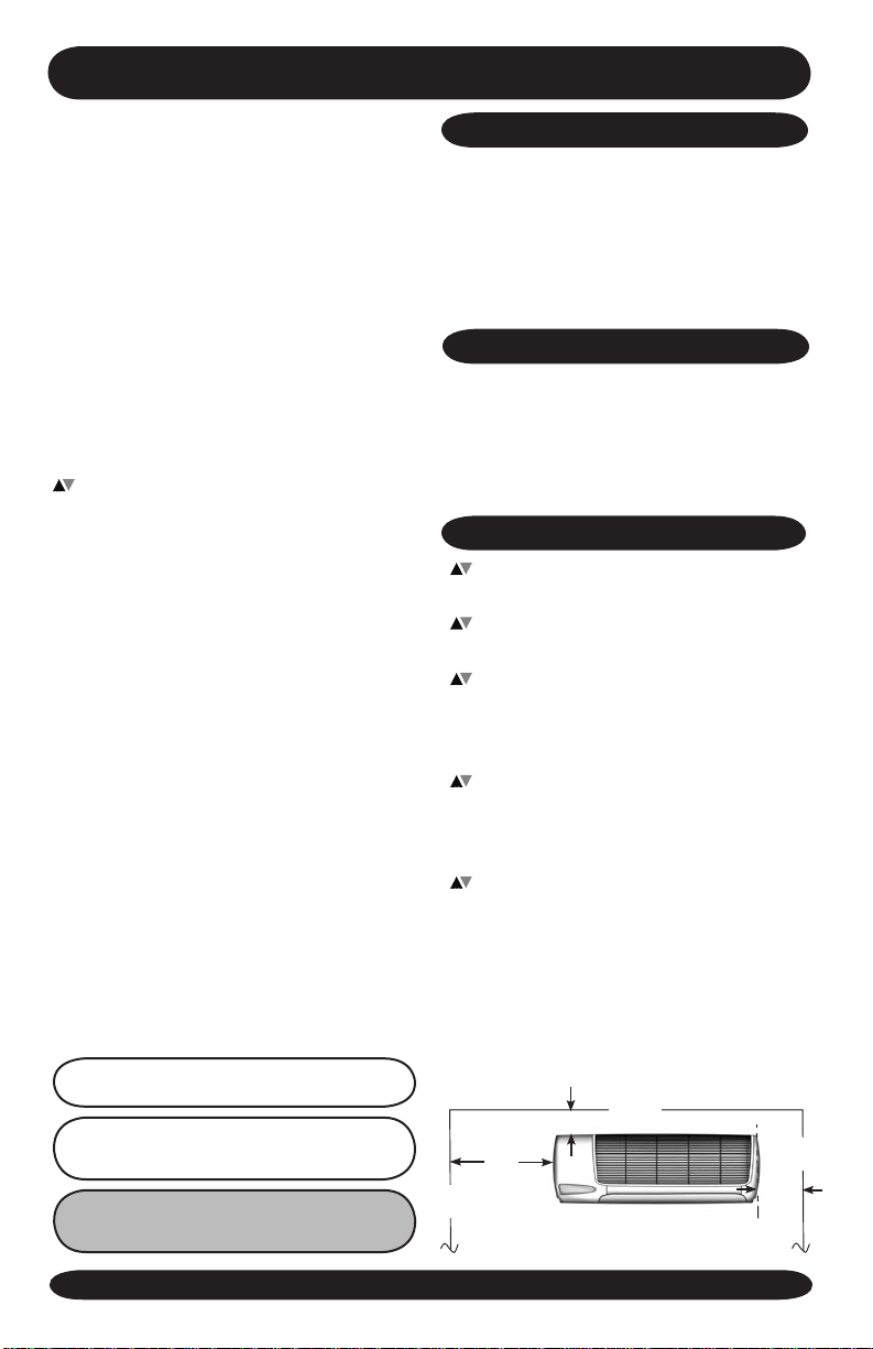
To ensure serviceability and proper
air distribution, the unit should be
positioned as close as possible to the
center (left-to-right) of the wall. Minimum
distance from the ceiling is stated on the
template provided with the unit packag-
ing. The cabinet left and right end caps
must be accessible for removal without
obstruction. (See below)
CEiLinG
4” Minimum
10”
Minimum
WALL
Min.
WALL
6”
WLCA/WLHA High Wall Evaporator
4
www.enviromaster.com

WLCA/WLHA moUntinG prEpArAtion
*notE:
Unit mUstBE instALLEd
4 -inCHEs doWn from CEiLinG
The WLCA/WLHA must be mounted
plumb and level to a vertical surface to
prevent unit vibration and/or unwanted
noise. It is recommended that the unit
be mounted directly to a smooth surface
such as Sheetrock
®
wallboard or similar
material. If mounting to a masonry block
wall, there should be a smooth barrier
between the unit and the masonry block
WLCA/WLHA HiGH WALL Unit moUntinG
1. After determining the best location for
the unit, use the cardboard template
provided in the packaging.
2. Mark where the piping, electrical wiring
and condensate drain should penetrate
the wall.
surface to absorb any potential vibration
and prevent the formation of condensation
on the wall.
notE: If excessive noise or vibration is
experienced from a unit mounted to a masonry block wall, check to ensure the unit is
plumb and level. If noise or vibration persists,
contact the wholesale distributor.
5. Secure the bracket to the wall with the
appropriate screws (for wood) or an-
chors (for masonry). Ensure the bracket
is mounted in a manner that will support
the weight of the unit.
note: The wall hanging bracket slot is NOT
located in the center of the unit.
3. Determine the appropriate hole size and
cut through the wall.
4. Use the supplied wall bracket. For
shipping purposes, the wall bracket is
fastened to the back of the unit.
Remove and discard
these screws
WLCA/WLHA High Wall Evaporator
Mounting
slot
Slot for piping
6. To mount the unit to the bracket, align
the mounting slot on the back of the
unit over the bracket and make certain
it ts properly.
notE: Piping may be roughed in before
wallboard or panels are placed in new
construction. PVC pipe (3” or 4” I.D.)
may be used as a pipe chase.
notE: Panels should remain on the unit
at all times, while powered and in operation. Service should be performed by a
QUALIFIED service agency. An annual
system check by a qualied service technician is recommended.
5
www.enviromaster.com

WLCA/WLHA HiGH WALL EVAporAtor instALLAtion instrUCtions
Electrical Wiring site preparation
All wiring should be in accordance with the
National Electric Code (NEC) and the local
building codes.
1. Make sure power is off.
2. Check the unit rating plate for circuit am-
pacity and breaker or time delay fuse size.
Use only HACr type breakers. Select
the proper wire for the ampacity rating.
3. Each unit must have a separate branch
circuit protected by a time delay fuse or
breaker. Refer to the unit rating plate
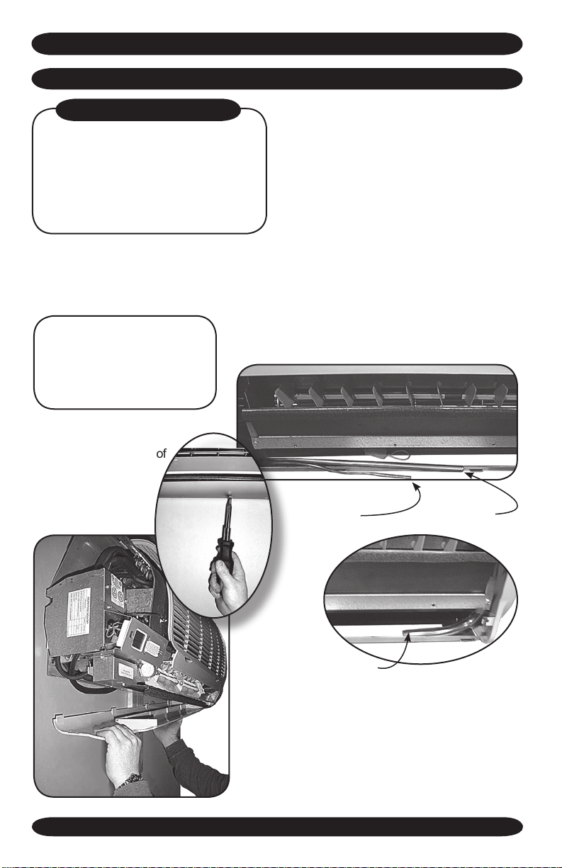
Locate Electrical Wiring
Helpfull Hint:
Prior to re-
m o v e i ng
the endcap
and bottom
use a small
board to prop
the unit away
from the wall.
Board
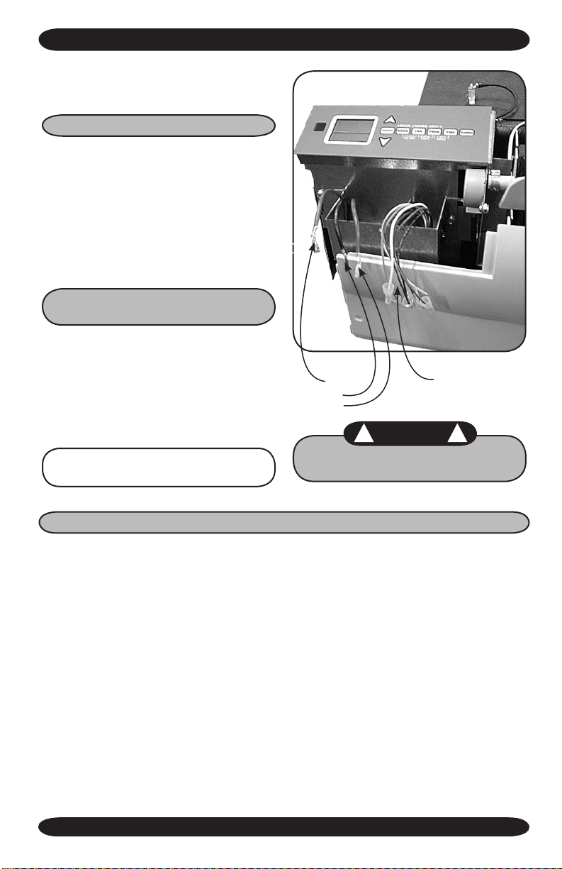
1. The left end cap of the unit needs to be
removed to access wiring diagram and
electrical wiring. This entails removal of
three screws.
for the proper wire and breaker or time
delay fuse size.
4. Inspect the existing wiring for any defects
such as cut or frayed wires. Replace if
any such wiring if found.
NOTE: On units rated 208/230V, the
primary side of the transformer is
factory wired for 230V. For a 208V
power supply, the transformer tap
must be changed from orange to
red. Refer to the wiring diagram
located on the inside of the left end
cap of the unit.
2. Lift and remove the front grill to expose
the third screw.
3.
Once the screws are removed,
slide t he left end cap
off to expose control
box and locate the
wiring diagram on
the inside of the
end cap.
WLCA/WLHA High Wall Evaporator
control box
6
Remove screw
www.enviromaster.com
WLCA/WLHA HiGH WALL EVAporAtor instALLAtion instrUCtions
4. To access High and Low wiring remove
the screw on the front of the control box.
High Volt Electrical Wiring
5. Refer to the wiring diagram to connect
the power wire to Black L1 and the other
wire to Red or White (115V) L2 at the
power connector location.
6. Connect the ground wire to the ground
lug or lead at the same location in the
control box.
Low Volt interconnect Wiring
for Unit mounted controls
the 24V control transformer is located
in the evaporator. This provides low Volt
control power to both the evaporator and
condenser. Depending on the models se-
lected, the low Volt interconnect control
wiring may be effected.
Note: All low Volt interconnect
wiring must be at least 18 AWg.
Ground
L1
L2
WArninG
! !
Be sure to keep any un-used wires
insulated with a wire nut or crimp.
Lo w Vo lt age
Connections
Units With or Without Heat
Cooling only units utilize two low
Volt
interconnecting wires between the indoor
and outdoor units.
• Wires designated “Y” (yellow) and “C”
(brown) of the air handler should be con-
nected to the corresponding “Y” (yellow)
and “C” (brown) wires or terminals of the
condenser. (See Figure 1A)
• Other wires or terminals such as “R” (red)
or “O” (orange) may not be needed and
should be protected by a wire nut from
making contact with the junction box or
other metal surfaces.
WLCA/WLHA High Wall Evaporator
Heat Pump Connection: In addition to the
“Y” and “C” connections required for cool-
ing, heat pumps require a reversing valve
control wire “O” (orange) that is energized
in the cooling mode.
If the indoor unit has an electric heater, then
a ”W” (white) wire connection will also be
needed to energize the indoor electric heat.
If a remote thermostat is used.
Heat pumps models require an “R” connec-
tion between the indoor and outdoor unit to
provide power to the defrost control board
in the condenser. (See Figure 1B)
7
www.enviromaster.com

WLCA/WLHA HiGH WALL EVAporAtor instALLAtion instrUCtions
LoW VoLt intErConnECt WirinG for Unit moUntEd ControLs
Units With or Without Heat continued
Unit mount Controls
Straight Cool
Figure 1A
Not used
Low Volt interconnect diagram intercon-
nect diagram
Figure 1A and Figure 1B
for unit mounted controls.
remote thermostat Controls
the 24V control transformer is
located in the air handler unit. This
provides low Volt control power to
both the air handler and condenser.
Depending on the models selected,
the interconnect control wiring may
be effected.
Heat pump Connection
Unit mount Controls
Two-Stage Heating
Figure 1B
Not used
When connecting to a defrosting heat
pump, such as EMI model S1HA, indoor
units with electric heat utilize ve interconnecting low
Volt wires between the indoor
and outdoor units.
Figure 2 A
notE: All low Volt interconnect
wiring must be at least 18 awg.
notE: For remote thermostat mode
the key pad will have limited opera-
tion - Sequence of Operation - Wall
Mounted Thermostat, page 21.
Choosing a remote Wall mounted
thermostat: See “Wall Thermostat
Control” section page 21.
WLCA/WLHA High Wall Evaporator
8
www.enviromaster.com

WLCA/WLHA HiGH WALL EVAporAtor instALLAtion instrUCtions
Heat pump Connection remote thermostat – two-stage Heating
Low Volt interconnect diagram interconnect diagram figures 2A, 2B & 2C for remote wall thermostat control.
Depending on the thermostat re-
quired or selected, air handlers may
utilize four to six low
Volt intercon-
Figure 2 B
necting wires between the indoor
unit, thermostat and outdoor unit.
Some thermostats do not require
the use of the “C” (brown) connec-
tion. In this case, ensure that any
unused wires are insulated with a
wire nut to prevent them from mak-
ing contact with the junction box or
other metal surfaces.
If the indoor unit has electric heat
then a “W” connection is required be-
tween the thermostat and indoor unit.
notE: If the control is con-
gured for unit mount control do NOT connect a wall
thermostat to the unit.
Figure 2 C
Refer to low Volt interconnect
diagr am inte rconn ect d iagra m
Figures 2A, 2B & 2C for remote
wall thermostat controls.
• Some thermostats do not require
the use of the “C” (brown) con-
nection.
• Heat pump operation requires
the connection of the “O” (or-
ange) terminal from the outdoor
unit to the thermostat.
The reversing valve is energized
in the cooling mode for EMI models
S1H heat pump condensers.
Ensure that any unused wires are
insulated with a wire nut to prevent
contact with the junction box or other
metal surfaces.
Once certain all electrical connetions
are made replace control box cover.
SINgLE-ZONE HEAT PUMPS ONLY Two-
stage heating requires the combination of
a heat pump condenser and an indoor unit
that is equipped with an electric strip heater.
The indoor electric heater will energize as
the second stage heat source (the tem-
perature is dependent on the thermostat
selected) and also during the defrost mode
control box
WLCA/WLHA High Wall Evaporator
Replace screw
for models S1HA.
9
www.enviromaster.com
WLCA/WLHA HiGH WALL EVAporAtor instALLAtion instrUCtions
rEfriGErAnt pipinG
pipinG do’s And don’ts
• Avoid piping on a rainy day.
• Use refrigerant grade copper tubing.
• Use a tubing bender and avoid unnec-
essary bending.
• Cap ends of lines until ready for nal
connections.
Once the unit is mounted and level
the WLCA/WLHA piping connections can
be made by removing the left end cap and
bottom panel:
note: The left end cap must
be removed prior to removing the bottom. follow the
instructions on page 6 for
removing the end cap.
1. Remove the Philips-head
screws on bottom of
unit and lift bottom
panel off.
The WLCA/WLHA is equipped with a
Flo-Rater/Piston Expansion device. Con-
nections are sweat type.
The suction line (large) must be insulated
the entire length with closed cell, foam tube
insulation. Do not insulate the liquid line
(small). Connect the outdoor unit according
to the instructions supplied with unit.
All horizontal piping runs must be level and
without dips to trap the oil.
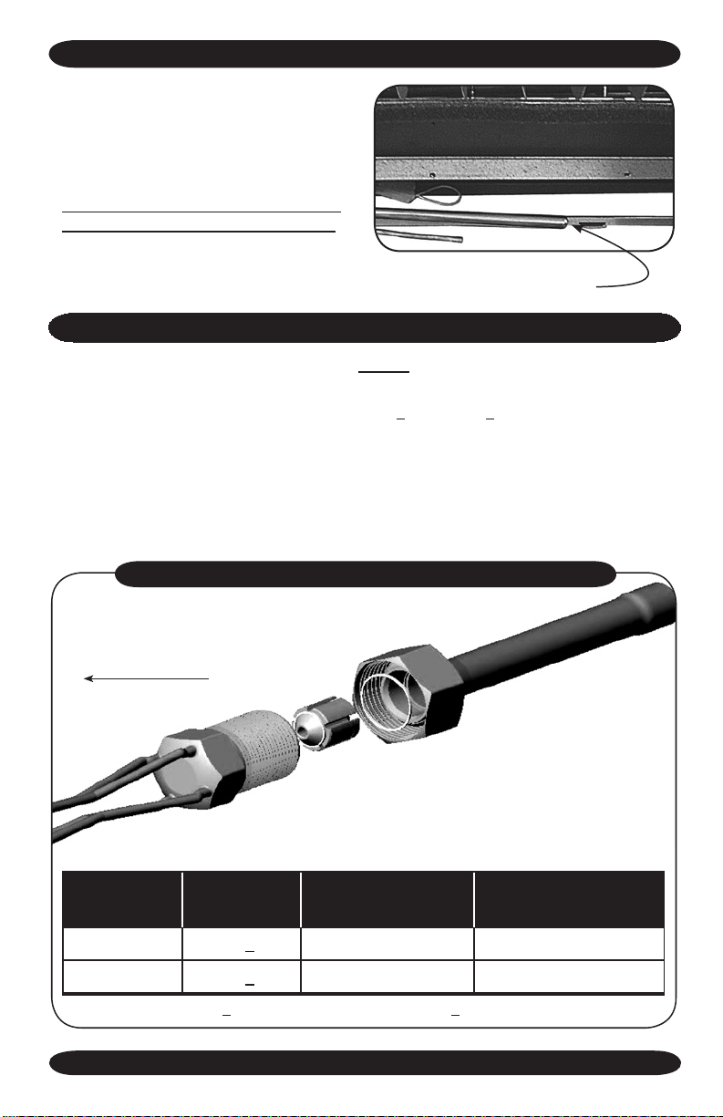
2. Exposed piping and condensate drain
connections. (See table on page 36 for
connection size per unit capacity.)
Liquid line
suction line
WLCA/WLHA High Wall Evaporator
condensate drain
When matching a the WLHA24 with an
18,000 Btuh condenser circuit, the inter-
connecting suction line needs to be 5/8”
O.D. to match the condenser service valve
connection. Therefore the 3/4” O.D. suc-
tion connection of the WLHA24 unit needs
to be reduced to 5/8” at the WLHA24 unit
connection.
10
www.enviromaster.com
rEfriGErAnt pipinG
Any change in the diameter of the tubing
must be made at the indoor connection.
Line-set diameter is determined by the
condenser service valve size.
Use of a larger diameter liquid or suction line can harm the compressor!
piston/orifiCE instALLAtion instrUCtion
WLH24
reducing bushing goes here for
18,000 Btuh system match
Important:
Replace the existing piston (before installing the unit) with the piston
supplied in Kit Bag when any:
• WLHA24 evaporator is matched with a
S1CA8000 or S1HA8000
condenser which has
an 18,000 Btuh compressor (“8” in the capacity decoding eld). The piston will need
relacement only on the 18,000 Btuh zone.*
Your EMI evaporator unit contains the appropriate piston for your model. Refer to this
document to determine if a change is required based on your condenser rating. If your
match is not listed below no piston change is required. (See chart below)
propEr instALLAtion of piston/orifiCE rEpLACEmEnt
Evaporator
model #
Evaporator
Condenser
Btuh
factory installed
Piston/Orice Size
field Changeover
Piston/Orice Size
WLHA24
WLHA24
WLCA/WLHA High Wall Evaporator
S1CA8000 .059” .053”
S1HA8000 .059” .053”
* “8” in the capacity decoding eld = 18,000 Btuh
11
www.enviromaster.com
WLCA/WLHA HiGH WALL EVAporAtor instALLAtion instrUCtions
rEfriGErAnt proCEssinG
WArninG
! !
It is illegal to discharge
refrigerant into the atmosphere.
Use proper reclaiming methods
and equipment when installing or
servicing this unit.
Finish all pipe connecting before
proceeding to charging the system.
Follow the instructions in the outdoor
unit for line evacuation, opening service
valves, and nal charge adjustments. Op-
eration charts and charge tables can be
found in the EMI Condenser IOMs.
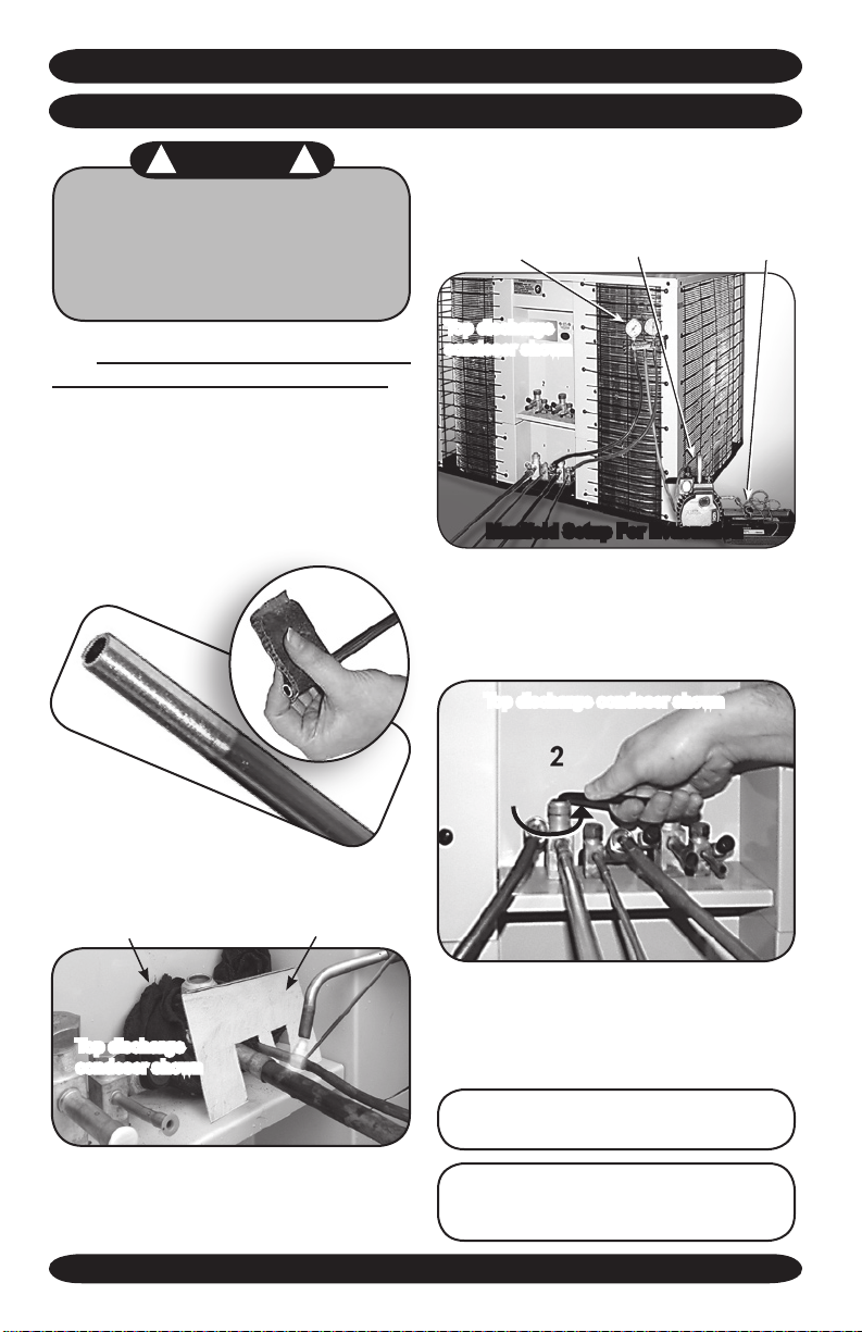
1. Clean the ends of tubing and insert into
ttings.
4. Braze tubing into ttings.
5. Attach manifold set.
Manifold
Top discharge
condeser shown
Vacuum Pump Micron Gage
manifold setup for Evacuation
6. Evacuate line to 500 microns or less to
ensure all moisture has been removed
and there are no leaks.
Top discharge condeser shown
2. Protect the valves by wrapping with a
wet rag "heat sink" before brazing.
heat sink
Top discharge
condeser shown
shield
3. We recommend the use of a shield (can
be made from some scrap metal) to
protect the paint.
WLCA/WLHA High Wall Evaporator
7. Once certain of a good evacuation and
leak free joints, back-seat the valves
(counter-clockwise) to open and allow fac-
tory charge to ll lines and indoor unit.
Refer to Charts in condenser manual to
“ne tune” the refrigerant charge.
WLCA30 & WLCA36 utilize a TXV (Thermo
Expansion Valve), which should be set at
10°f superheat.
12
www.enviromaster.com
 Loading...