

EMI VPAC30, VPAC36, VPHP30, VPHP36 Installation, Operation And Maintenance Manual
VP AC/VPHP 30-36
INST ALLA TION, OPERA TION, AND MAINTENANCE MANUAL
Nominal Cooling Capacity: 30,000 - 36,000 Btuh
P/N 240-4554 Rev. 1.0 [03/04]
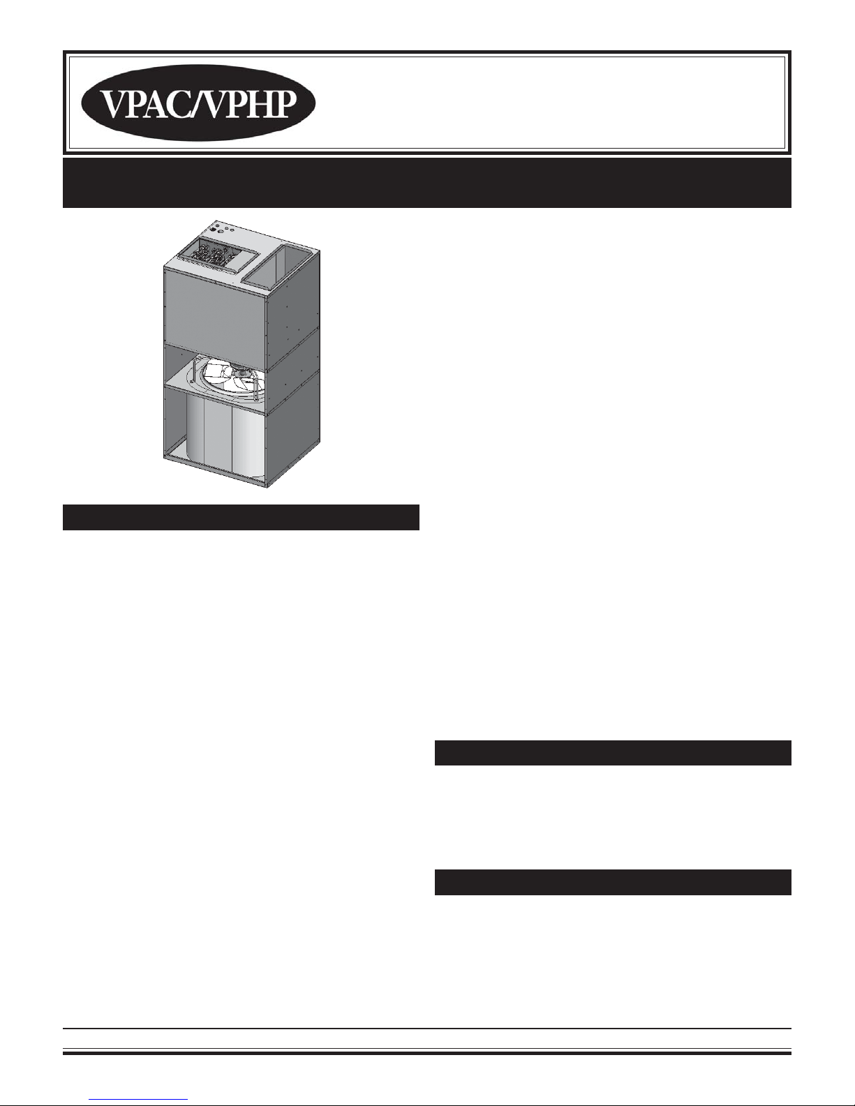
VPAC/VPHP 30-36 Single Package Vertical Air Conditioner
(SPVAC) and Heat Pump (SPVHP)
The VPAC/VPHP 30-36 offers an economic benefit
when used in a multi-room suite by supplying conditioned air to more than one room without the need to
install another PTAC/PTHP. This is also a design advantage since the second room does not need an exterior wall for a second unit.
The VPHP 30-36 heat pump is intended to be a limited range heat pump, which means utilizing a supplemented heat option is recommended since heat pump
operation will cease at approximately 40°F outdoor
temperature. Consult factory for availability of a full
range defrosting heat pump version.
PRODUCT DESCRIPTION
The VPAC/VPHP 30-36 single package vertical air
conditioner (SPVAC) and heat pump (SPVHP) creates new options in layout and space utilization. The
VP AC/VPHP 30-36 offers low cost operation and quiet,
comfortable air distribution, especially when used in
multi-room suites, apartments, healthcare facilities,
and homes.
Framed into a concealed closet enclosure for low operating sound levels, the VPAC/VPHP 30-36’s vertical discharge vent allows ducting to the top of the
room(s) for superior air circulation and distribution. Multiple air supply grilles can distribute air when used with
a soffit and intake grilles can be located on the sides
of the enclosure.
The VPAC/VPHP 30-36 can be applied in a ducted
return air application or can remain non-ducted as delivered. If ducted, the closet enclosure does not require minimum clearances other than what is recommended for adequate service access. If non-ducted,
minimum clearance options must be adhered to as
dictated for optimal performance and sound. See note
on minimum clearance dimensions in the illustation
titled ”Exploded View Of Typical Installation” on page
2 of this document. (Figure 1)
Enviromaster International, LLC
Each system is supplied with a ready-to-install wall
sleeve and outdoor louver . The cabinet is constructed
with 20 gauge galvanized steel with a G-90U corrosion resistant rating and the insulated top discharge
evaporator compartment provides quiet ducted, conditioned air delivery to other room location(s).
The VPAC/VPHP 30-36 is backed by EMI and ECR
International and is tested and rated in accordance
with ARI standard 390 and UL-1995. Due to ongoing
product development, product designs and specifications may change without notice. Please contact the
factory for more information.
CONDENSA TE REMOV AL
The VP AC/VPHP 30-36 requires an internal drain system due to its unique draw-thru condenser design.
Condenser side drain stub(s) are integral to the chassis and are very easy to connect a drain hose to.
AIR SYSTEMS
Motors are thermally protected PSC type. Air stream
surfaces are insulated with 1/4 inch fiberglass or 1/8
inch volara. The evaporator fan is a forward curved
type directly mounted to the motor shaft. The condenser propeller utilizes a draw-thru design for improved efficiency.
1
www.enviromaster.com/vpac
ELECTRICAL WIRING
WARNING
! !
Before accessing the control compartment, disconnect power to the unit. Failure to do so could result
in serious injury or electrical shock.
All field wiring must be done in accordance to NEC
and local codes. Check the unit rating plate for circuit
ampacity and breaker(s) or fuse size(s). Use only
HACR type breakers or time delay fuses. Select the
proper wire for the ampacity rating. Some units require more than one power supply. Check the nameplate and wiring diagram for further instructions.
IMPORTANT: The unit is wired for 230V primary
voltage from the factory. The transformer must be
rewired by the installer if the jobsite voltage is 208V .
Each vertical unit is equipped for a 24V wall thermostat connection.
• Front mounted control box
• Manual fresh air damper
• Microprocessor control board
- Universal control board: can be used in straight
cool electric, hydronic heat, or cooling/heat
pump applications.
- Fan purge: fan remains on for 60 seconds after heat/cool call is dropped (“auto” mode only)
- Anti-short cycle compressor protection
- Random start timer: prevents multiple units
from simultaneous start-ups (straight cool only)
- Freeze protection: prevents evaporator freeze
ups
- Low ambient lockout: prevents compressor operation in cold outdoor temperatures.
- Test operation: all timers are eliminated to allow ease of testing after installation (straight cool
only)
- Compatible with fossil fuel, electric heat, mercury or electronic thermostats
- Refrigerant hot gas bypass for operation in low
outdoor ambient conditions (cooling cycle only)
ST ANDARD CONTROLS AND COMPONENTS
• Cooling or heat pump chassis w/high efficiency
scroll or reciprocating type compressor
• Custom wall sleeve
• Anodized aluminum outdoor louver for field installation (optional colors available)
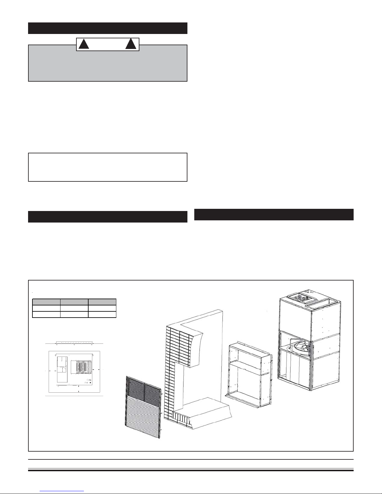
FIGURE 1 - EXPLODED VIEW OF TYPICAL INST ALLATION
ROUGH W AL L SLEEVE OPENI NG
Unit Size Width Height
30 28 9/16" 32 3/8"
36 28 9/16" 36 1/4"
For designed performance, sound levels,
and service, maintain a minimum of 6” on
both sides and front for non-ducted return
air applications only.
6”
6”
OPTIONAL CONTROLS AND COMPONENTS
• Supplemental electric heat
• 265/277V (contact factory for availability)
• Painted condenser louver
• Remote wall thermostat
• Return air access panel (w/disposable return air
filters)
Ducted return air applications only require
6”
minimal spacing for service requirements.
Consult ECR Engineering if these mini-
mums can not be met. Depending on the
application and return air introduction,
some reconfiguration is likely to be accommodated.
VPAC/VPHP
2
Manufactured in Rome, NY, USA
INSPECTION
Carefully check the shipment against the bill of lading. Make sure all chassis, wall sleeves, and louvers
(as well as any options) have been received. Inspect
each component for damage. The carrier must make
proper notation on the delivery receipt of all damage
identified and complete a carrier inspection report.
Concealed damage must be reported to the carrier
within 15 days of the receipt of the shipment.
IMPORTANT: The purchaser must notify the EMI
traffic department of all damage and is responsible
for filing any necessary claims with the carrier.
APPLICA TION LIMIT A TIONS
The VPAC/VPHP 30-36 should be installed in
accordance with all national and local safety codes.
Minimum and maximum operation conditions must be
observed to assure maximum system performance
with minimum service required. Refer to table below
for application limitations of the VPAC/VPHP 30-36.
APPLICATION L IM ITAT IONS
Outdoor Ambient Air Temperature °F
Mi nimum DB Maximum D B
Cool
67
Cool Heat
115 75
in the wall for the wall sleeve and louver be the correct dimension and in the exact position necessary
for installation. (Figure 1)
The platform height should be the same level as the
bottom of the wall opening. Because wall sleeve
depths can vary depending on overall wall thickness,
it is critical that wall thickness be determined
before
ordering the wall sleeve. (Figure 2) Consult factory
for available wall sleeve sizes.
FIGURE 2 - DETERMINING WALL SLEEVE DEPTH
½” x ½” Foam Gasket
Outdoor Louver
Drip edge will
extend outside
exterior wall
when installed
to guide condensate away
from building
Wall Sleeve Depth = Overall W all
Thickness - 1.25” (Louver Depth)
Overall Wall
Thickness
Exterior Wall
Wall Sleeve
Interior Wall
Lag Holes
(4 Per Side)
Indoor Ambient Air Temperature °F
Minimum Maximum
DB/WB D B DB/WB DB
Cool Heat Cool Heat
67/57 50 90/72 80
CAUTION
! !
Avoid possibility of electric shock and personal injury. Disconnect all power before removing chassis or performing any cleaning, servicing, or maintenance.
GENERAL INST ALLA TION
Enviromaster International recommends installing the
VPAC/VPHP 30-36 before any carpentry work is
started for the enclosure. It is very important for proper
air flow and sound levels that a minimum clearance of
6” between the enclosure and the chassis be maintained. It is also very important that the rough opening
Wall Sleeve
Assembly
Cross Section
of Typical Wall
1. Install 1/2” x 1/2” or 1” x 1” foam tape (supplied)
to the unit condenser top and sides to seal against
the wall sleeve. (Figure 3)
FIGURE 3 - INSULATION & WEATHER ANGLES
Install supplied
1/2” x 1/2” foam
insulation along
top and sides of
condenser box.
(IMPORTANT:
Position as far
forward toward
outdoor side as
possible.)
Weather Angle
Position (One on
each side)
Enviromaster International, LLC
3
www.enviromaster.com/vpac
 Loading...