

EMI VPAC, VPHP Installation, Operation & Maintenance Manual

VPAC/VPHP
SINGLEPACKAGE
VERTICALAIRCONDITIONER/HEATPUMP
Straight Cool/Heat Pump
Nominal Capacities: 9,000-12,00015,000-17,000-19,000-24,000 Btuh
FOR NEW CONSTRUCTION ONLY
Enviromaster International LLC
5780 Success Dr.
Rome, NY 13440
INSTALLATION,OPERATIONANDMAINTENANCEMANUAL
Email: info@retroaire.com
VPAC/VPHP
An ISO 9001-2000 Certified Company
P/N# 240004198, Rev. 1.9 [06/06]
VPAC/VPHP SINGLE PACKAGE VERTICAL AIR CONDITIONER/HEAT PUMP
INSTALLATION , OPERATION, AND SPECIFICATION MANUAL
P/N# 240004198, Rev. 1.9 [06/06]
Shipping Damage MUST be Reported to the Carrier IMMEDIATELY!!!
Examine the exterior. Remove cover and examine compressor and piping for signs of damage.
This manual is intended as an aid to qualified service
personnel for proper installation, operation, and maintenance
of the VPAC/VPHP Packaged Terminal Air Conditioner
(PTAC). Read these instructions thoroughly and carefully
before attempting installation or operation. Failure to
follow these instructions may result in improper installation,
operation, service, or maintenance, possibly resulting in
fire, electrical shock, property damage, personal injury, or
death.
TO THE INSTALLER
(1) Retain this manual and warranty for future refer-
ence.
(2) Before leaving the premises, review this manual
to be sure the unit has been installed correctly
and run the unit for one complete cycle to make
sure it functions properly.
To obtain technical service or warranty assistance
during or after the installation of this unit, contact
your local representative.
retroaire.com for a local representative listing. For
further assistance call 1-800-228-9364.
Visit our website www.
SAFETY INSTRUCTIONS
Read all instructions before using the VPAC/VPHP
PTAC. Install or locate this unit only in accordance
with these instructions. Use this unit only for its
intended use as described in this manual.
Check the rating plate on the VPAC/VPHP PTAC
before installation to make certain the voltage
shown is the same as the electric supply to the
unit.
The VPAC/VPHP PTAC must be connected only to
a properly grounded electrical supply. Do not fail
to properly ground this unit.
Turn off the electrical supply before servicing the
VPAC/VPHP PTAC.
Do not use the VPAC/VPHP PTAC if it has dam-
aged wiring, is not working properly, or has been
damaged or dropped.
[Save These Instructions]
When calling for assistance, please have the following information ready:
• Model Number_________________________
• Serial Number_________________________
• Date of installation______________________
Recognize this symbol as an indication
!
The Right Fit For Comfort
of important safety information
!
DANGER
!
The RetroAire PTAC must:
Be connected to a properly grounded
electrical supply with the proper voltage
as stated on the rating plate.
Have proper over current protection (i.e.
time- delay fuse/HACR-Breaker) as listed
on the Rating Plate.
Failure to follow these instructions can result
in a fire, explosion, or electrical shock causing
property damage, personal injury, or death.
2
!
www.retroaire.com
TABLE OF CONTENTS
To the Installer and Safety Instructions ....................2
Warnings and Installer Responsibilities ...................3
Controls and Components ......................................4
Product Description, Air System .............................4
Heat-exchanger, Refrigeration, Electrical Wiring ....4
Insection, Installation Instructions ........................5-9
Sequence of Operation ....................................10-12
Cleaning and Maintenance .................................... 12
Troubleshooting .................................................... 12
Specifications and Dimensions ........................13-14
Warranty ............................................................... 15
MODIFICATION AND TAMPERING
DANGER
!
Tampering with the VPAC/VPHP is dangerous
and may result in serious injury or death. Tampering voids all warranties. Do not attempt to
modify or change this unit in any way.
IMPORTANT SAFETY FEATURE
!
INSTALLER RESPONSIBILITIES
This manual has been prepared to acquaint you with the
installation, operation and maintenance of this VPAC/
VPHP PTAC and to provide important safety information
in these areas.
We urge you to read all of the instructions thoroughly before
attempting the installation or operation of this unit. This
manual should be kept for future reference.
The manufacturer of this unit will not be liable for any dam
ages caused by failure to comply with the installation and
operating instructions outlined in this manual.
A rating plate identifying this VPAC/VPHP PTAC can be
found on the unit. When referring to your unit, always have
the information listed on the rating plate readily available.
Power Cord With Integral Safety Protection
All PTACs rated 250
to the power supply are equipped with a power cord
with integral safety protection as standard. Providing
personal shock protection as well as arcing and
fire prevention, the device is designed to sense
any damage in the line cord and disconnect power
before a fire can occur. Tested in accordance with
Underwriters Laboratories, the cord set also offers a
unique “passive” operation, meaning the unit does not
-
require resetting if main power is interrupted.
WARNING - A DAMAGED POWER SUPPLY CORD
MUST BE REPLACED WITH A NEW CORD FROM
THE MANUFACTURER, AND NOT REPAIRED.
Each power cord should be checked before every
use. Follow the instructions in the order listed on the
device.
WARNING - DO NOT USE THE PRODUCT IF THE
UNIT FAILS THE TEST.
V or less that are cord connected
Completely read all instructions prior to assembling, installing, operating, or repairing
this product. Inspect all parts for damage prior to
installation and start-up. The VPAC/VPHP PTAC
must be installed ONLY by qualified installation
personnel.
VPAC/VPHP
WARNING
!
3
!
Made in Rome, New York, USA
PRODUCT DESCRIPTION
ELECTRICAL WIRING Continued
The VPAC/VPHP Single Package Vertical Air Conditioner (SPVAC) and Heat Pump (SPVHP) creates new options in layout and space utilization. The VPAC/VPHP offers
low cost operation and quiet, comfortable air distribution,
especially when used in multi-room suites, apartments,
healthcare facilities, and homes.
Framed into a concealed closet enclosure for low operating sound levels, the VPAC/VPHP’s vertical discharge
vent allows ducting to the top of the room(s) for superior air
circulation and distribution. Multiple air supply grilles can
distribute air when used with a soffit and intake grilles can
be located on either of the two sides of the enclosure.
The VPAC/VPHP offers an economic benefit when used
in a multi-room suite by supplying conditioned air to more
than one room without the need to install another unit. This
is also a design advantage since the second room does
not need an exterior wall for a second unit.
Each system is supplied with a ready-to-install wall
sleeve and a condenser side air louver. The cabinet is
constructed with 20 gauge galvanized steel with a G-90U
corrosion resistant rating. The unit is designed with serviceability on three sides (front, left, and right). The insulated top
discharge evaporator compartment provides quiet ducted,
conditioned air delivery to other room location(s).
AIR SYSTEMS
Motors are thermally protected PSC type. Air stream
surfaces are insulated with 1/4 inch fiberglass or 1/8 inch
volara. The evaporator fan is a forward curved type directly
mounted to the motor shaft. The condenser propeller and
slinger ring (for condensate re-evaporation) utilize a blowthru design for improved efficiency.
IM PORTANT:
condensate drain system will be used. The standard
VPAC/VPHP is designed to evaporate condensate by
slinging it onto the warm condenser coil.
Co nsult the factor y if an internal
ELECTRICAL WIRING
All field wiring must be done in accordance to NEC and
local codes. Check the unit rating plate for circuit ampacity
and breaker or fuse size. Use only HACR type breakers.
Select the proper wire for the ampacity rating. If a plug and
receptacle are used check the proper fit.
The unit is wired for 230V primary voltage from
the factory. The transformer must be rewired by the
installer if the jobsite voltage is 208V.
Each vertical stack unit is equipped for a 24V wall
thermostat connection. Units are shipped with a twenty
foot plenum rated thermostat wire utilizing a quick connect
plug to the unit.
STANDARD CONTROLS AND COMPONENTS
• Cooling or heat pump chassis w/high efficiency rotary
or reciprocating type compressor
• Indoor/outdoor mounting anodized outdoor louver for
field installation (optional colors available)
• Manual fresh air damper (located on service panel
below evaporator coil)
• Front mounted control box (unless otherwise specified)
• Microprocessor control board
- Fan purge: Fan remains on for 60 seconds after
heat/cool call is dropped (“Auto” mode only)
- Universal control board: circuit board can be used
in either a straight cool electric, hydronic heat, or
cooling/heat pump application.
- Anti-short cycle compressor protection
- Random start timer: prevents multiple units from
simultaneous start-ups
- Freeze protection: prevents evaporator freeze
ups
- Low ambient lockout
- Test operation: allows ease of testing after installation (all timers are eliminated)
- Compatible with fossil fuel, electric heat, mercury
or electronic thermostats
• Temperature sensitive drain pan valve for heating condensate disposal (VPHP only)
• Wall sleeve
WARNING
!
Before accessing the control compartment, disconnect
power to the unit. Failure to do so could result in serious
injury or electrical shock.
The Right Fit For Comfort
!
OPTIONAL CONTROLS AND COMPONENTS
• Hydronic heat coil
• Electric heat coil
• Painted outdoor air louver
• Wall thermostat (digital or mercury bulb)
• Power disconnect
• EMS management relay
• Casters (for easy maneuverability )
• Return air access panel (standard white or custom
colors available)
4
www.retroaire.com
INSTALLATION FOR NEW CONSTRUCTION
INSPECTION
Carefully check the shipment against the bill of lading.
Make sure all chassis, wall sleeves, and louvers (as well as
any options) have been received. Inspect each component
for damage. The carrier must make proper notation on
the delivery receipt of all damage identified and complete
a carrier inspection report. Concealed damage must be
reported to the carrier within 15 days of the receipt of the
shipment.
IMPORTANT:
The purchaser must notify the EMI traffic
department of all damage and is responsible for filing
any necessary claims with the carrier.
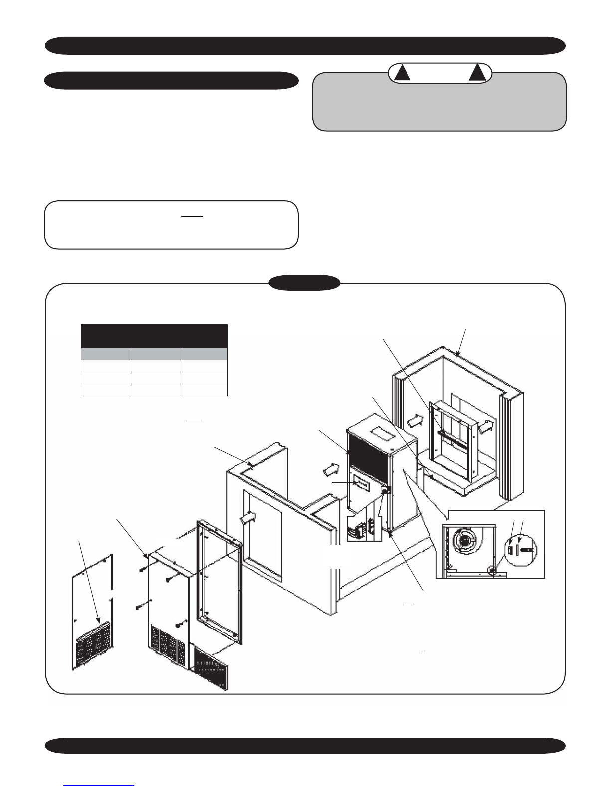
Figure 1
EXPLODED VIEW OF TYPICAL INSTALLATION
VPAC/VPHP ROUGH WALL
SLEEVE OPENING
Unit Size Width Height
9-15 26.125” 26.125”
17 26.125” 26.625”
19-24 26.125” 33.625”
For proper intake air flow on the VPAC/VPHP
09-17, a minimum spacing of 4” must be maintained between the enclosure and the unit.
For VPAC/VPHP 19-24, use 6” minimum spac
ing between the enclosure and the unit.
-
Platform (Supplied By Installer)
Note: Height = Floor To Bottom
Of Wall Opening
CAUTION
!
!
Avoid possibility of electric shock and personal injury.
Disconnect all power before removing chassis or per
forming any cleaning, servicing, or maintenance.
Enviromaster International recommends installing the
unit before any carpentry work is started for the enclosure.
It is very important for proper air flow and sound levels that
a minimum clearance of 4” (09-17) or 6” (19-24) between
the enclosure and the chassis be maintained. It is also very
important that the rough opening in the wall for the wall
sleeve and louver be the correct dimension and in the exact
position necessary for installation. (Figure 1)
Minimum overall wall thickness must be at
least 5” for straight cool models and 6½” for
heat pumps. (Consult factory if minimum
O.D. Air Splitter Baffle
Evaporator Coil
wall thickness cannot be met.)
-
Access Panel (Optional)
Filter Slide (On Back)
Rear View of Door
VPAC/VPHP
Lagging Holes
Manual Fresh
Air Door
(2) 1/4 - 20 Serrated Nuts Washer
T-stat Connections
(different on
VPAC/VPHP 24)
External line cord (min. 48”) located at bottom
right for front and right hand controls or bottom
left for left hand controls
For a VPAC/VPHP with optional hydronic heat attached to the supply air panel:
It is still necessary to maintain minimum spacing between the enclosure and the unit
for proper air flow but additional space is recommended for the hydronic option. Refer
to Page 5 of these instructions to determine spacing for serviceability and access to
piping connections.
5
Made in Rome, New York, USA
 Loading...