

EMI UNHV09, UNHV12, UNHV18, UNHV24 Installation, Operation And Maintenance Manual
UNHV
V
p
A
r
Variable Speed Ductless Split System
ariable Speed Ductless S
Air Handler
ir Handle
Straight Cool / Heat Pump Nominal Capacities
UNHV09 UNHV12 UNHV18 UNHV24 Units
9,000 12,000 18,000 24,000 Btuh
2.6 3.5 5.3 7.0 kW
8,800 10,000 18,000 21,000 Btuh
2.5 2.6 5.0 5.6 kW
Installation, Operation and
Maintenance Manual
lit System
COOL
HEAT
An ISO 9001-2008 Certifi ed Company
ECRInternational,Inc.
2201 Dwyer Avenue,
Utica NY 13501
web site: www.ecrinternational.com
P/N# 240009098, Rev. C [08/08/2012]

TABLE OF CONTENTS
Receiving Information .................................................................................................................. 3
Important Safety Information ........................................................................................................ 4
Dimensional/Physical Data ............................................................................................................ 5
General Product Information ......................................................................................................... 6
Unit Mounting ............................................................................................................................. 8
Ceiling Mounted .......................................................................................................................... 8
Wall Mounted .............................................................................................................................. 8
Condensate Piping ......................................................................................................................10
Refrigerant Piping .......................................................................................................................11
Refrigerant Processing .................................................................................................................13
Electrical Wiring .........................................................................................................................15
Cabinet Re-Assembly ..................................................................................................................20
Condenser Operation ..................................................................................................................21
Initial Start-Up ...........................................................................................................................23
UNHV Controller .........................................................................................................................24
Wired Wall Controller ..................................................................................................................25
Setting The Controller .................................................................................................................27
Hand Held Controller Operation ....................................................................................................29
Wired Wall Controller Operation ....................................................................................................32
Controller Features .....................................................................................................................33
Controller Fault Conditions ...........................................................................................................34
Maintenance ..............................................................................................................................35
Troubleshooting ..........................................................................................................................36
Frequently Asked Questions .........................................................................................................38
Specifi cations And Dimensions .....................................................................................................39
UNHV System Options .................................................................................................................40
Test Unit Performance Data Sheet .................................................................................................41
Check our website frequently for updates: www.enviromaster.com
Information and specifi cations outlined in this manual in effect at the
time of printing of this manual. Manufacturer reserves the right to
discontinue, change specifi cations or system design at any time without
notice and without incurring any obligation, whatsoever.
2

RECEIVING INFORMATION
Shipping damage MUST be reported to the carrier IMMEDIATELY.
Examine exterior.
Remove cover and examine compressor and piping for signs of damage.
General Information
Installation shall be completed by qualifi ed agency. Retain
this manual and warranty for future reference.
Installer review this manual to verify unit has been installed
correctly. Run unit for one complete cycle to verify proper
function.
To obtain technical service or warranty assistance during or
after installation, contact your local representative.
Visit our web site www.enviromaster.com for local
representative listing.
For further assistance call 1-800-325-5479.
When calling for assistance, please have following
information ready:
Model Number_________________________
Serial Number_________________________
Date of installation______________________
3

IMPORTANT SAFETY INFORMATION
Become Familiar With Symbols
Identifying Potential Hazards.
!
All fi eld wiring shall conform to requirements of authority
having jurisdiction or in absence of such requirements:
• United States - National Electrical Code, ANSI/NFPA 70
• Canada - CSA C22.1 Canadian Electrical Code Part 1.
!
WARNING
Fire and electrical shock hazard. Improper
assembly and/or installation could result in death or
serious injury. Read this manual and understand all
requirements before beginning installation.
Become Familiar With Symbols
Identifying Potential Hazards.
!
DANGER
Indicates a hazardous situation which, if not
avoided, WILL result in death or serious injury.
Safety Information
• Installation by qualifi ed personnel.
• Turn off electrical supply before servicing unit.
• Inspect all parts for damage prior to installation and
start-up.
Do not use unit if it has damaged wiring, is not working
properly, or has been damaged or dropped.
• Connect to properly grounded electrical supply with
proper voltage as stated on rating plate.
• Have proper over-current protection (i.e. time- delay
fuse/HACR Breaker) as listed on Rating Plate.
• Connect unit to properly grounded electrical supply. Do
not fail to properly ground this unit.
• Check the rating plate on the unit before installation to
verify voltage shown is same as electric supply to the
unit. Rating plate is located on top panel only.
• Tampering voids all warranties.
!
WARNING
Tampering with this unit is dangerous and could
result in serious injury or death. Do not modify or
change this unit.
!
WARNING
Indicates a hazardous situation which, if not
avoided, could result in death or serious injury.
!
CAUTION
Indicates a hazardous situation which, if not
avoided, could result in minor or moderate injury.
NOTICE
Indicates information which should be followed to
ensure proper installation and operation.
4
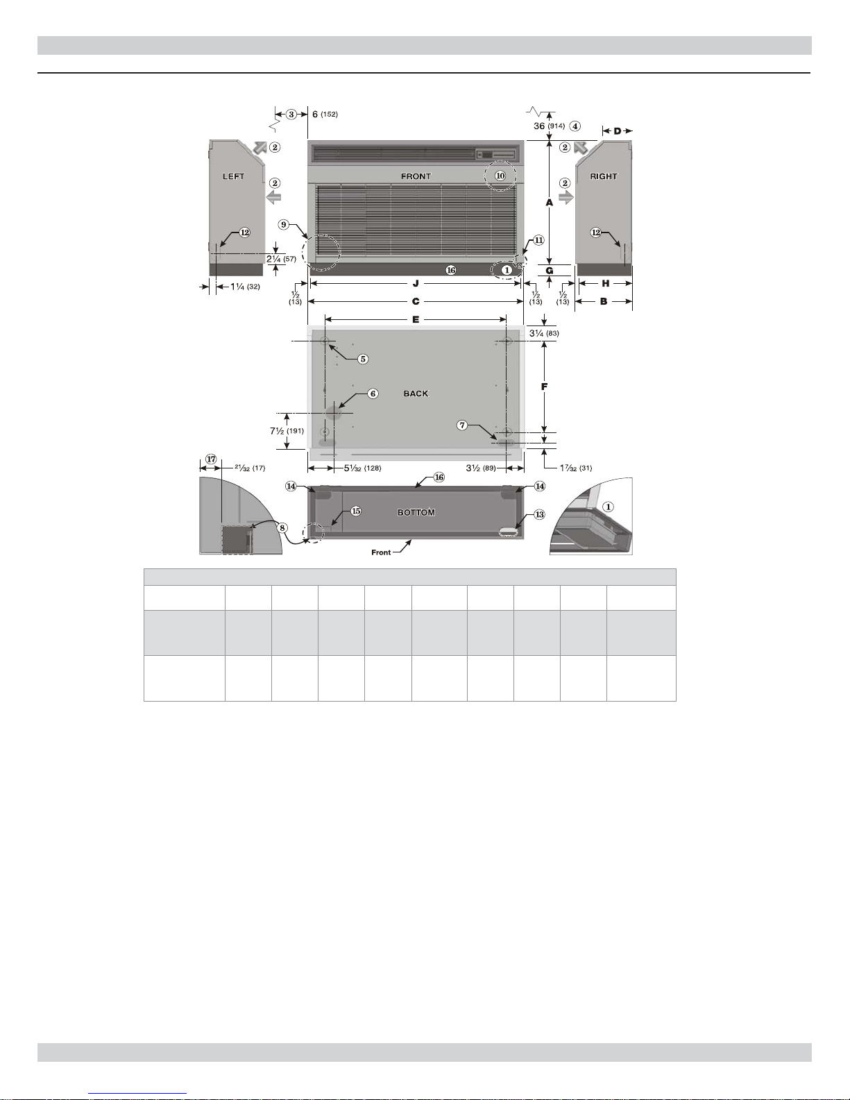
DIMENSIONAL/PHYSICAL DATA
Figure 1 - Dimensions, Openings And Knockouts
Model A B C D E F G H J
UNHV09/12
UNHV18/24
1.
Optional condensate pump fl oor
26”
(660)
26”
(660)
mount location (requires toe kick kit).
2.
Supply and return air fl ow directions.
3.
Minimum clearance for air fl ow and
access — BOTH sides of cabinet.
4.
Minimum clearance — insure
minimum clearance of 36" (914 mm)
above supply air outlet and in front of
return air inlet for air fl ow and access.
5.
Clearance holes (4) for securing unit
to wall or ceiling, using appropriate
hardware 11/
6.
Knockout, 3" (76 mm), for optional
"
diameter.
16
customer supplied/installed fresh air
intake device.
7.
1⅝" x 3 ⅜" knockout each side of
rear panel for refrigeration tubing,
condensate drainage and/or power.
DIMENSIONS — Inches (mm)
11”
(279)
11”
(279)
41 ½”
(1054)
51 ½”
(1308)
8.
Opening, ⅞" x ⅞" bottom right front
5 ½”
(140)
5 ½”
(140)
35”
(887)
45”
(1141)
corner of cabinet, for condensate
drain tube routing when unit is ceiling
mounted
9.
Refrigeration and condensate draining
connections are located in this area
10.
Electrical connections are located in
this area
11.
Location of item 7, above
12.
1⅝" x 3⅜" knockout each side panel
for refrigeration tubing, condensate
drainage and/or power
13.
1⅝" x 3⅜" knockout at bottom
left front for refrigeration tubing,
condensate drainage and/or power,
used when unit is ceiling mounted.
Pump kit riser fl anges do not interfere
with knockouts.
19 3/16”
(487)
19 3/16”
(487)
2 ½”
(64)
2 ½”
(64)
10
7
/16”
(265)
10
7
/16”
(265)
14.
40 ½”
(1029)
50 ½”
(1283)
1⅝ "x 3⅜" knockouts at
bottom left rear each side for
refrigeration tubing, condensate
drainage and/or power; pump
kit riser fl anges do not interfere
with knockouts.
15.
1⅝" x 3⅜" knockout at bottom
right front for refrigeration
tubing, condensate drainage
and/or power, most often used
when unit is ceiling mounted;
pump kit riser fl anges do not
interfere with knockouts
16.
Optional toe kick — with 1"
bottom fl ange; recessed ½"on
front and sides, fl ush at rear.
17.
Distance from side of cabinet to
⅞" x ⅞" opening.
5

GENERAL PRODUCT INFORMATION
Product Description
• UNHV is available as (DX) direct expansion straight cool
or heat pump.
• Unit is equipped with unit mounted infrared compatible
controls which support 24V Wired Wall Controller
operation. Optional handheld remote is available.
• Heat pump models provide up to 24, 000 Btuh of cooling
and 21,000 Btuh of heating. Electric heat options are
available for up to 5 kW of supplemental heat.
Can be matched with EMI’s:
• Single-zone condensing units — S1HV 09-24.
• Condensers include common discharge port.
• Heat pump circuits include common suction port.
Controls And Components
Cabinet Features:
(Factory-Installed Or Supplied)
• Single unit-mounted control package, confi gurable
to either unit mount or remote Wired Wall Controller
operation.
• Unit mount control can be used in cooling only, cooling
with electric heat, heat pump, or heat pump with second
stage electric heat applications.
• Operational range set point temperature adjustable
between 55°F (13°C) and 90°F (32°C) in one-degree
increments.
• Infrared-compatible controller allows use of IR hand
held controller.
• Operation modes include Heat, Cool, Dry, Fan and Auto
Change-over.
Optional Equipment
rate condition speeds for set-ups and charging.
• Non-volatile back-up memory maintains control settings
for indefi nite period during power outage. When power
is restored equipment resumes operation after threeminute compressor time delay.
• 7-day programmable with copy feature.
• Filter change indicator: Timer indicates when fi lter
should be cleaned.
• Integral condensate pump safety-switch connection
microprocessor monitors condensate pump safety switch
and displays error code when fault occurs. (Only with
optional condensate pump).
• CEC (California Energy Commission) compliant.
• Condensate drain pan over fl ow protection.
• Accessible, washable, reusable, nylon mesh fi lter.
• Access to piping connections and condensate pump
allow installation with unit mounted in place.
• Condensate drain pan constructed of galvanized steel
(G90U), anti-corrosion coating.
• Condensate pump (fi eld installed only).
• 24V Wired Wall Controller.
• Electric heat with automatic reset high temperature
cutout and redundant high temperature fuse link (when
heat option is selected, factory installed only).
• Fan Operation – Auto/On. High, Medium or Low speed
fan.
• Fan Purge – Fan remains on for 60 seconds after Heat/
Cool call is dropped. (Auto mode only)
• Room air sampling — Selectable time intervals insure
fan will cycle on periodically, in Auto Fan Mode.
• Selectable Fahrenheit (°F) or Celsius (°C) temperature
scale.
• Dry mode – Operates cooling and electric heat
simultaneously to remove humidity.
• Anti-Short Cycle Compressor Protection.
• Minimum ON time for heating and cooling eliminates
room temperature droop and system short cycling.
• Freeze Protection – Prevents air handlers freeze up.
• Test operation – Allows testing after installation. Runs at
Installer Supplied Items
• Low voltage wiring (18 AWG minimum required).
• High voltage power supply wiring.
• Mounting screws and fasteners.
• Condensate piping.
• Refrigerant piping (if not supplied). Both tubes need
to be insulated.
• Refrigerant (for interconnect charge) R410A.
6
GENERAL PRODUCT INFORMATION
Installation Considerations
• Determine best location for mounting unit for room air
circulation.
• Locate outdoor and indoor units as close together as
possible.
• Determine wiring, drainage and piping placement.
• Insure interconnect tubing is within listed limits. See
Table 1 .
Table 1 - Tubing Specifi cations - Both Tubes
Insulated
S1CV/
S1HV
or
Model
09
12 1/4" 1/2"
18 3/8" 5/8" *
24 3/8" 5/8" *
* Bush down at air handler
• Position unit as close as possible to center (left-toright) of wall. Grille on unit front must be accessible for
servicing.
Max.
Length
Equivalent
Feet
100’
(30 m)
Max.
Lift
“H” “P” O.D. O.D.
35’
(11
m)
Max.
Trap
Height
20’
(6 m)
Liquid
Line
1/4" 1/2"
Suction
Line
Condensate Pump Kit Option
• Verify condensate pump purchased with unit See
Table 2 .
• Floor-mounted units with fl oor-mounted condensate
pump optional toe kick kit. See Table 2 .
NOTICE
If excessive noise or vibration from unit mounted to
masonry block wall, verify unit is plumb and level. If
noise or vibration persists, contact distributor.
Table 2 - Condensate Pump Kits, UNHV 09-24
Floor-Mounted Units
Air Handler 208/230v 115v
09 / 12 550001727 550001728
18 / 24 550001727 550001727
Toe kick kit is required when condensate pump is
mounted below fl oor-mounted air handler.
Ceiling-Mounted Units
Air Handler 208/230v 115v
09 / 12 240006200 240006199
18 / 24 240006200 240006199
Table 3 - Toe Kick Kits
Air Handler Part number
09 / 12
18 / 24
Required when condensate pump is
mounted below fl oor-mounted air
handler.
Table 4 - Drain Pan Extension Kits
550001785
550001786
Optional Toe Kick Kit
• For fl oor-mounted UNHV units use optional toe kick kit.
See Table 3 .
• Toe kick kit is required if fl oor mounting a condensate
pump under fl oor-mounted UNHV air handler.
Site Preparation
• Mount unit to vertical surface plumb and level to
prevent unit vibration and potential noise.
• Mount unit directly to smooth surface such as wallboard
or similar material.
• Mounting to masonry block wall,provide smooth
barrier between unit and masonry block surface to
absorb potential vibration and prevent formation of
condensation on the wall.
• Unit can be suspended from ceiling using threaded
rods.
7
Ceiling Mounted Units
Air Handler
09/12
18 / 24
Recommended when unit is ceiling
mounted
Kit #
550001915
550001916
UNIT MOUNTING
Unit Mounting Instructions
1.
Optimal unit location:
• Locate unit in area with unrestricted air fl ow to the
space.
• Unit may be recessed into wall or ceiling by no more
than 5½” (140mm).
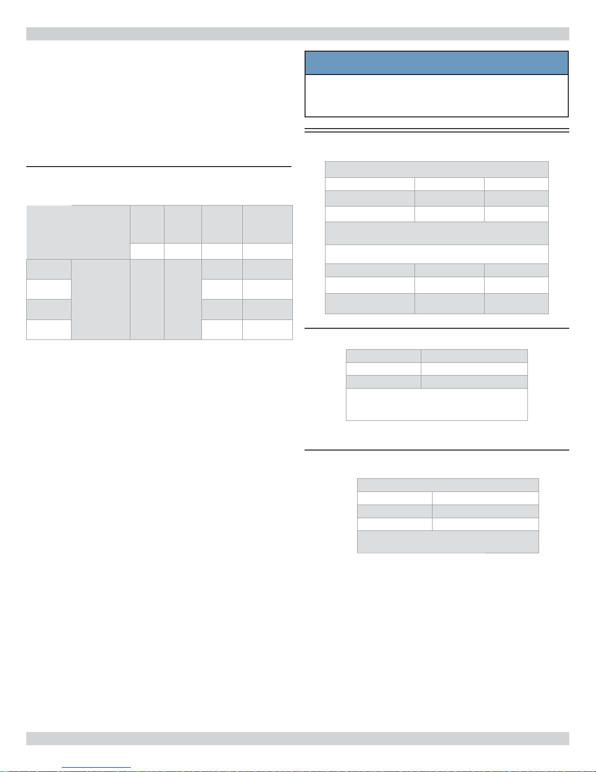
2.
Use cardboard template provided in packaging to mark
where piping, electrical wiring and condensate drain
should penetrate wall or ceiling.
3.
See Figure 1, Page 5 for locations of cabinet openings
and knockouts.
4.
New construction - Piping may be roughed in before
wallboard or panels are placed. PVC pipe (3” or 4”
I.D.) may be used as pipe chase.
NOTICE
Do not install unit in location where curtains or
drapes obstruct supply air grille. This may cause air
to recirculate without cooling the room, and may
result in premature system failure.
5.
Determine appropriate hole size. Cut through wall or
ceiling.
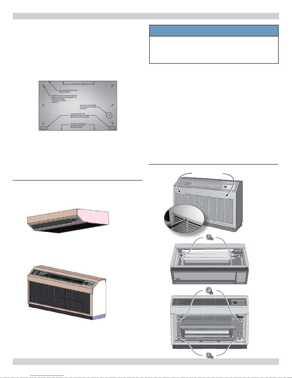
6.
Remove return air grille by removing screws on front of
grille. Lift grille off. See Figure 3 .
7.
Remove rest of painted cabinet. See Figure 3 :
A. Completely remove center screws.
B. Loosen (do not remove) four remaining screws
(5/16" slotted hex) so there is approximately
1/2” between screw head and keyhole slot. Reach
through front of unit to access screws as shown.
C. Leaving loosened screws on unit will make
reinstalling the cabinet easier.
D. If unit is recessed into wall or ceiling it may be
necessary to completely remove all screws.
E. Slide painted cabinet upward until keyhole slots
clear screws. Lift off.
Figure 3 Removing Front Grill
Grille screws
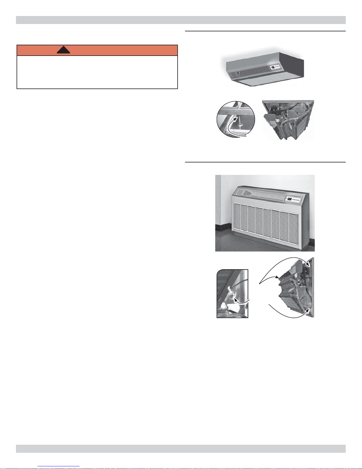
Figure 2 - Mounting Options
Ceiling Mounted
Wall Mounted
Loosen top
screws
Remove center
screws
Loosen
bottom screws
8
UNIT MOUNTING
Unit Mounting Instructions
!
WARNING
Electrical shock hazard. Replace all panels after
installation or servicing. Panels must remain on unit
at all time while powered and in operation. Failure to
do so could result in death or serious injury.
Ceiling Mounting
Threaded rods may be inserted through mounting holes to
suspend unit from ceiling supports. Verify unit is mounted
to support its' weight. See Figure 4 .
Wall Mounting
Secure unit to wall with wood screws or anchors for
masonry using mounting holes located in back panel of
unit. See Figure 5 .
Figure 4 Ceiling Mounting
Threaded
Rod
Figure 5 Wall Mounting
Mounting
holes (2
each side)
9

CONDENSATE PIPING
T
UNHV is supplied with two ½" I.D. fl exible PVC hoses for
connection to copper or plastic condensate drain pipe work.
• Each drain line is labeled and plugged at the factory.
• Unplug appropriate line and connect to condensate
drain.
• Consider following information when installing UNHV:
A. Install with highest point in condensate hose at
unit’s drain pan. Insures proper drainage.
B. Slope condensate hose down in the direction of
water fl ow with minimum gradient of 1” (5mm) per
10’ (1m). There must not be any uphill gradients.
C. When multiple units are connected to common
condensate drain, insure drain is large enough
to handle volume of condensate from all units.
Recommend having air vent in condensate hose to
prevent air locks.
D. If using accessory condensate pump, follow pump
manufacturer instructions.
Use condensate hose tie downs in ceiling mount
applications.
Figure 6 Condensate Piping
Condensate
Hoses
Condensate hose tie down
and knock-out for ceiling
mount application
Two sets of labeled
condensate hoses,
fl oor or ceiling
mount. Check the
Condensate hose
label (fl oor mount
shown)
label to ensure correct hose is used
for the application.
10

REFRIGERANT PIPING
line
Piping Preparation
• Avoid piping on wet and rainy days.
• Use only clean, refrigeration-grade copper tubing.
• Use tubing benders to guard against kinking.
• Verify no burrs remain on fi ttings.
• Cap ends of lines until ready for connections. Verify
plastic end caps remain in place when inserting through
wall openings.
• Insulate both lines.
• Isolate tubing from transmitting vibration to building or
unit and avoid contact with sharp edges.
• Wrap refrigeration valves with wet rag “heat sink” to
protect valves while brazing. See Figure 9, Page 12
• DO NOT use suction line size larger than condenser
service valve connection. This can harm compressor.
Install reducer, when used, only at air handler
connection.
• Mount and level per instructions. See “UNIT
MOUNTING” on page 8 .
Figure 7 Refrigerant Connections
Liquid line
Suction line
• See Figure 7 locations of piping connections in UNHV
unit.
Knockout for piping removed
See Figure 1, Page 5 for locations of all knockouts and
openings in the cabinet.
11

REFRIGERANT PIPING
Line Sizing
1.
Size lines per Table 12, Page 39 .
2.
Match suction line size with condenser service valve
connection.
• When matching UNHV18 or 24 with 18,000 or
24,000-Btuh condenser, use 5/8" suction line, with
reducer installed at indoor connection.
3.
Changes in diameter of tubing must be made at
indoor connection. Line-set diameter is determined by
condenser service valve size.
Refrigerant Piping
1.
Clean the ends of tubing and insert into fi ttings. See
Figure 8 .
2.
Protect valves by wrapping with a wet rag “heat sink”
before brazing. See Figure 9 .
3.
Use a shield to protect the paint as shown in Figure 9 .
(The shield can be made from scrap metal.)
4.
Braze tubing into fi ttings.
Pressure test all fi eld installed piping with nitrogen. Using
suitable vacuum pump, evacuate tubing and indoor unit to
500 microns or less, with service valves remaining front
seated (closed).
Figure 8 Clean ends of tubing
Figure 9 Place Wet Rag “Heat Sink" Over
Valves Plus A Sheet Metal Shield To
Protect Paint
Shield
Wet rag heat sink
NOTICE
Pressure test all fi eld installed piping with nitrogen.
Using suitable vacuum pump, evacuate tubing and
indoor unit to 500 microns or less, with service
valves remaining front seated (closed).
12
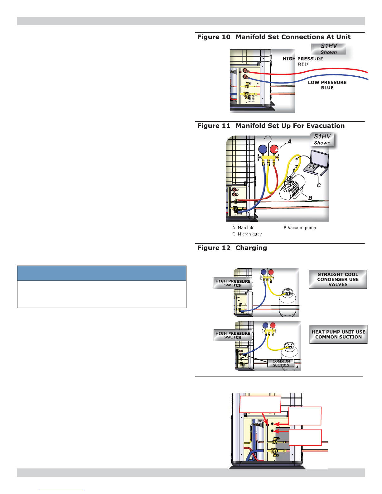
REFRIGERANT PROCESSING
Refrigerant Processing
1.
Attach manifold set, vacuum pump, & Micron Gauge.
See Figure 10.
2.
Evacuate line to 500 microns or less to insure all
moisture has been removed and there are no leaks.
See Figure 11.
A. Evacuate
B. Pressurize with 100psi N2 or Nitrogen
C. Evacuate again
D. Charge with R410A
3.
Verify evacuation and leak free joints. Back-seat valves
(counter-clockwise) to open and allow factory charge to
fi ll lines and indoor unit. See Figure 13.
Refer to refrigerant charge table for specifi ed charge.
4.
Charge to proper weight. Charge based on feet of
interconnect. Only add/remove R410A in liquid
form. See Table 5, Page 14 .
5.
Install all panels removed to this point. Panels are required for proper air fl ow.
All systems require fi eld charge adjustments. Refer to
“Refrigerant Charge Tables” for proper weight charge
and Operation Charts for proper system pressures and
temperatures at different outdoor conditions. Sub-cool
should be used for fi nal system charge.
Charge with dial-a-charge or weighed in with scale.
NOTICE
It is illegal to discharge refrigerant into the
atmosphere. Use proper reclaiming methods &
equipment when installing or servicing this unit.
Units are delivered pre-charged with refrigerant for
condenser coil and air handler. Charging of fi eld installed
piping is required. Refer to refrigerant charge table for
proper amount to be added for applications interconnect
piping. Unit service valves are solid brass, for sweat
connections.
• Measure all heat pump saturated suction pressures at
Common Suction Port not vapor service valve.
• Common Suction Port includes pressure drop and
temperature increase through reversing valve resulting
in more accurate and complete system charge.
• Port may also be used to charge system in heating
mode when both sides of line set are at high system
pressures or to determine saturated evaporator
pressure while in heating mode.
Figure 13 Common Suction, Common
Discharge, & High Pressure Switch
HIGH PRESSURE
SWITCH
COMMON
DISCHARGE
PORT
COMMON
SUCTION
PORT
13
REFRIGERANT PROCESSING
Use following example to fi nd charge adjustment and
system charge for any air handles and tubing length.
Line Adjustment = (Line Charge/FT) x Line Length
System Total = Factory Charge + Line Adjustment
Round to nearest ounce and allow for gauges and hoses.
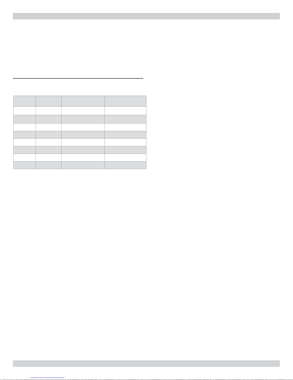
Table 5 - S1CV / S1HV R410A Refrigerant
Charge Table
Condenser
S1CV9000 UNHV09 .25 oz./ft 23 g/m) 39.5oz (1120g)
S1CV2000 UNHV12 .25 oz./ft 23 g/m) 39.5oz (1120g)
S1CV8000 UNHV18 .64 oz./ft 59 g/m) 54.0oz (1531g)
S1CV4000 UNHV24 .64 oz./ft (59 g/m) 54.0oz (1531g)
S1HV9000 UNHV09 .25 oz./ft (23 g/m) 39.5oz (1120g)
S1HV2000 UNHV12 .25 oz./ft 23 g/m) 39.5oz (1120g)
S1HV8000 UNHV18 .64 oz./ft (59 g/m) 54.0oz (1531g)
S1HV4000 UNHV24 .64 oz./ft (59 g/m) 54.0oz (1531g)
Wall Unit
Pairing
Line Charge
Per Foot
Factory
Charge
14
 Loading...