

EMI UNHG09, UNHG12, UNHG18, UNCG-30, UNHG24 Installation, Operation And Maintenance Manual
UNCG/UNHG
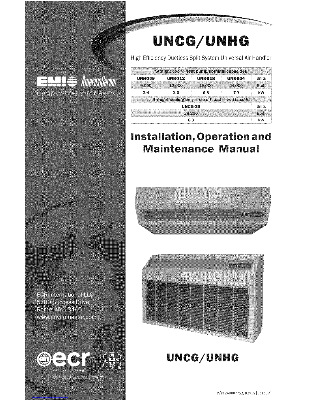
High Efficiency Ductless Split System Universal Air Handler
UNHG0g i UNHG12 i UNHG18 i UNHG24
UNCG-30
8_3
Installation, Operation and
Maintenance Manual
UNCG/UNHG
P/N 240007753, Rev. A [0515091
Contents ...................... 2
Read Before Proceeding ............ 3
Verify Unit Before installing .......... 4
Piston/Orifice Replacement (when required)..6
Mounting the Unit ................ 7
Electrical Wiring ................. 12
Condensate Piping ............... 17
Refrigerant Piping ............... 18
Refrigerant Processing ............ 21
Reassemble the UNCG/UNHG Cabinet . . 22
Initial Start-Up .................. 23
UNCG/UNHG Controller Overview ..... 24
Setting the Controller ............. 26
Unit-Mounted Controller Operation .... 29
Remote Thermostat Operation ....... 33
AmericaSeries Controller Features ...... 36
AmericaSeries Controller Fault Conditions. 37
Maintenance ................... 38
Troubleshooting ................ 40
Frequently Asked Questions ......... 44
Specifications and Dimensions ....... 46
UNCG/UNHG System Options ........ 48
Test Unit Performance Data Sheet ..... 50
EMI's Product Line ............... 51
Indoor Units ................... 51
Outdoor Units .................. 51
shippingdo ogoMust
bo opo todtot.o orHor
INMEDIATELY.
Examine the exterior. Remove
cover and examine compressor
and piping for signs of damage.
_it_eEMI AmericaSeries high eNciency
air handlers is backed by EMi and
ECR international and is tested and
rated in accordance with AHR1 Standard
210/240 and UL-1995.
Due to ongoing product development,
product designs and specifications may
change without notice.
Please contact the f;actory for more
information.
iiiiiiiiiiiiiiiii
Retain this manual and warranty for
future reference. Befk_releaving the prem-
ises, review this manual to be sure the unit
has been installed correctly and run the
unit t_brone complete cycle to make sure
it _nctions properly.
To obtain technical service or warranty
assistance during or after the installation
ofthis unit, contact your local representa-
tive. For alocal representative listing, visit
our web site:
Www._nviro m;_ ster.¢om
For _rther assistancecall:
1-800-223-9364
"When calling _r assistance, please have
the following information ready:
Model Number
Serial Number
Date of installation
Comfort where it cour_ts 2 R!N 240007753, Bey A [05£509I
compmetemyreadaH instructions
prior to assemMing, instamming,oper=
ating, or repairing this product.
Inspect all parts for damage prior to
......................installation and start-up. The EMI
._ericaSeries high eNciency airhandles
must be installed ONLY by qualified
installation personnel
Tampering with this unit is da_ger-
ous. Tampering voids all warranties.
DO NOT attempt to modify or change
this unit in any way.
ilhe EMI AmericaSeries must:
Be connected to aproperly grounded
electrical supply with the proper
voltage as stated on the rating plate.
• Have proper overcurrent protection
(time-delay fase/HACR Breaker) as
listed on the rating plate.
Failure to follow these instructions can
result in a fire, explosion, or electrical
shock causingproperty damage, personal
injury_ or death.
'-_ismanualisintendedasanaidtoqua>
fledservice personnel for proper installa-
tion, operation, and maintenance of the
EMI AmericaSeries high efficiency air
handles. Read these instructions thor-
oughly and carefully before attempting
installation or operation.
ailuretofollowtheseinstructionsmay
result in improper installation, operation,
service, or maintenance, possibly resulting
infire,electricalshock,propertydamage,
iiiiiiiiiiiiiiiill
iiiiiiiiiiiiiiiiii
iiiiiiiiiiiiiiiiii
iiiiiiiiiiiiiiiiii
iiiiiiiiiiiiiiiiii
iiiiiiiiiiiiiiiiii
iiiiiiiiiiiiiiiiii
iiiiiiiiiiiiiiiiii
iiiiiiiiiiiiiiiiii
iiiiiiiiiiiiiiiiii
iiiiiiiiiiiiiiiiii
iiiiiiiiiiiiiiiiii
personal injury, or death.
Read all instructions before using this
unit. Install or locate this unit only in ac-
cordance with these instructions. Use this
unit only for its intended use as described
in this manual
Check the rating plate on the unit before
installation to make certain the voltage
shown is the same as the electric supply to
the unit. The rating plate is located on the
top panel only.
This unit must be connected only to a
properly grounded electrical supply. Do
not fail to properly ground this unit.
_l_rn offthe electrical supplybefore servic-
ing the unit.
Do not use the unit if it has damaged wir-
ing, is not working properly, or has been
damaged or dropped.
:'/N 240007753, Bey, A [05_ 50% 3 I'_$ade i_ the OoA
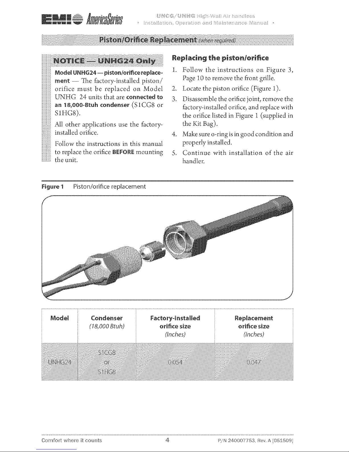
_odelUNHG24=piston/orificerepiace-
m_m-- _he_ctory-instaHedpiston/
orificemustbereplacedonMode_
UNHG 24 units that are connected to
.adl other applications use the factory-
installed orifice.
Follow the instructions in this manual
toreplacetheorifice_EFOREmounting
the unit.
Rep_a¢in_ {he Dis{on/orifice
1. Follow the instructions on Figure 3,
Page 10 to remove the front grille.
2. Locate the piston orifice (Figure 1).
3. Disassemble the orifice joint, remove the
factory-installed orifice, and replace with
the orifice listed in Figure I (supplied in
the Kit Bag).
4. Make sure o-ringis in good condition and
properly installed.
S. Continue with installation of the air
handler.
Figure I Piston/orifice replacement
_ode_ Condenser Factoryqnstalled Replacement
(18,000Btuh) orifice size orifice size
(Inches.} (Inches.}
Oomfort where it cou;'_ts 4 P!N 240007753, Bey A [05£50%
+ The AmericaSeries UNCG/UNHG
is available as a (Dx) direct expansion
straight cool and heat pump.
+ It offers a contemporary design in a
ductless type air handlers and combines
attractive appearance with high eNciency
conditioning for small to medium size
commercial or residential spaces.
The UNCG/UNHG is equipped with
unit mounted infrared compatible con-
trols which also supports 24V remote wall
thermostat operation. Optional handheld
remote is available.
Heat pump models provide up to
23,800 Bmh of cooling and 20,800 Btuh
of heating. Electric heat options are
available for up to S kW of supplemental
heat.
This American-made air handler of+
fers ease of installation, operation, and
service.
it can be matched with EMI's:
- Single-zone condensing units --
S1CG/SIHG 09-24 and $1CG 30.
Controls and components
{Factory-instaRed or supplied)
+ Large LCD Bacldit Display
Single unit-mounted control package,
configurable to either unit mount or re-
mote wall thermostat operation, increas-
ing installation flexibility.
Urlit mourfl: control -- Ifthe control is
configured for unit mount control DO
NOT connect a wall thermostat to the
unit. See Figure 27, Page 26+
+ Unit control can be used in cooling only,
cooling with electric heat, heat pump, or
heat pump with second stage electric heat
applications.
Operational range set point temperature
adjustable between SS°F and 90°F in one-
degree increments+
+ Infrared-compatible controller allows use
of optional IR hand held controller.
11111111111111111
S2CG/S2HG side discharge.
- Multi-zone, top discharge condens-
ing units -- T2CG/T2HG, T3CG/
T3HG, or T4CG/T4HG+
All EMI air handlers are backed by En-
viromaster international LLC and are
tested and rated in accordance with AR1
standards 210/240 and UL 199S+
Dual-zone condensing units -- +++++++++++++++++Unit-mounted controls are fhlly l_nc-
+++++++++++++++++tional without the handheld remote.
+ Operation modes include Heat, Cool,
Dry, Fan and Auto Change-over+
Fan Operation - Auto/On+ High or Low
speed fan
Fan Purge - Fan remains on for 60 sec-
onds after Heat/Cool call is dropped for
improved eNciency (Auto mode only)
Room air sampling -- Selectable time
intervals ensure the fan will cycle on peri-
odically, in Auto Fan Mode to help elimi-
nate room temperature stratification+
• Selectable Fahrenheit (°F) orCelsius (°C)
temperature scale.
• Drymode- Operates coolingand electric
heat simultaneously to remove humidity.
Optional electric heat must be selected.
• Anti-Short Cycle Compressor Protec-
tion.
c
:_/N 240007753, Bey A [05150% 5 Made i_ the OoA
• Minimum on time forbearing and cooling
Helps eliminate room temperature drop
and system short cycling.
• Freeze Protection - Prevents airhandlers
freeze up.
• Test operation- Allows easeoftesting af-
ter installaion (alltimers are reduced).
• Non-volatile back-up memory willmain-
tain control se_ings for an indefinite pe-
riod during apower outage. When power
is restored the equipment will resume
operation after a three-minute compres-
sor time delay.
• 7-dayprogrammable with copyfeature.
• Filter change indicator: A timer feature
indicaes when the filter shouldbe cleaned
according to the selected time.
• Modular design- reduces parts required
for control package. Deco panel, relay
board, ribbon cablesand microprocessor
are combined into one package.
• integral condensae pump safety-switch
connection where-by the microproces-
sor monitors the condensate pump safety
switch and displays an error code when a
fault occurs. (.Appliesonly with optional
condensae pump).
• CEC (California Energy Commission)
compliant.
• Condensae drainpan over flowprotec-
tion.
Optional Equipment
• Condensate pump (field installed only).
• 24V remote wall thermostat.
• Electric heat with automatic reset high
temperature cutout and redundant high
temperature _se link (when heat option
is selected).
• Hand-held infrared controller.
The control is configured for unit-
mountedcontrol(factorydefault).DO
NOT connect a wall thermostat to the
unit without changing configuration.
installer Supplied items
• Low voltage wiring (18 awg required).
• High voltage power supply wiring.
• Mounting screws and fasteners.
• Condensate piping.
• Refrigerant piping (if not supplied).
• Refrigerant (for interconnect charge).
Check equipment for damage prior
..................to installation, if damaged contact the
iiiiiiiiiiiiiiii_
wholesale distributor.
Cabinet Features:
• Easily accessible, washable, reusable,
nylon mesh filter.
• Easy access to piping connections and
condensate pump allows installation with
the unit mounted in place.
• Condensate drain pan constructed ofgal-
vanized steel (G90U), with anti-corrosion
coating.
• Modular snap-in, 7-day programmable
control with large bacldit LCD display,
a "Change filter" display feature and se-
lectable Fahrenheit (°F), or Celsius (°C)
temperature scale.
_e_ore ir_{aRin_, ¢o_sider:
• Determinethebestlocation_brmounting
the unit for room air circulation.
Locate outdoor and indoor units as close
together as possible.
Determine how power wire (high and
low voltage) condensate drainage, and
refrigerant piping maybe mn to and from
the unit.
• UNCG/UNHG - Ensure that intercon-
nect tubing is within the limits listed in
Table 2, Page 7.
Oomfort where it cour_ts @ P!N 240007753, Bey A [05£50%
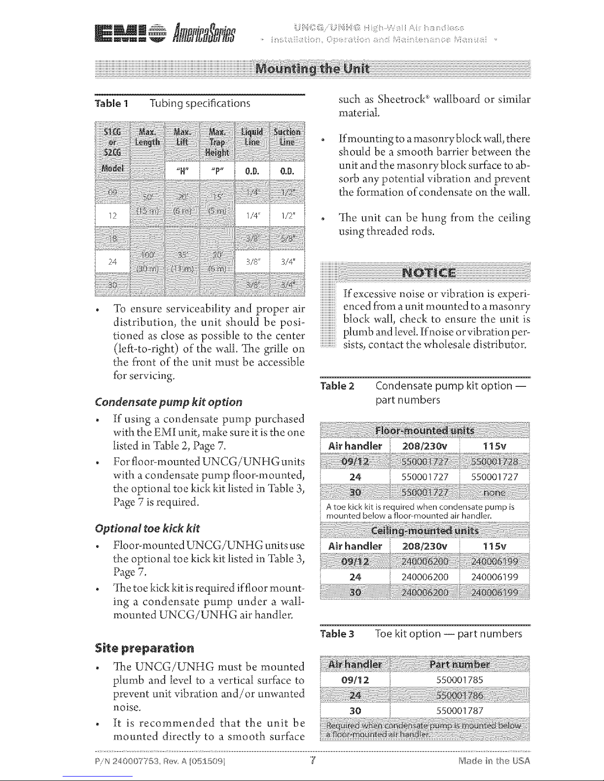
Table 1 Tubing specifications
O.D. O.D.
12
24
To ensure serviceability and proper air
distribution, the unit should be posi-
tioned as close as possible to the center
(left-to-right) of the wall. ?{laegrille on
the front of the unit must be accessible
for servicing.
Condensate pump kit option
• if using a condensate pump purchased
with the EMI unit, make sure it is the one
listed in "Fable 2, Page 7.
• For floor-mounted UNCG/UNHG units
with a condensate pump floor-mounted,
the optional toe kick kit listed in "Fable 3,
Page 7 is required.
Optional toekick Mt
• Floor-mountedUNCG/UNHG unitsuse
the optional toe kick kit listed in "Fable 3,
Page 7.
• _[he toe kick kit isrequired if floor mount-
ing a condensate pump under a wall-
mounted UNCG/UNHG air handler.
such as Sheetrock _ wallboard or similar
material.
If mounting to amasonryblock wall, there
should be a smooth barrier between the
unit and the masonryblock surface to ab-
sorb any potential vibration and prevent
the formation of condensate on the wall.
tltae unit can be hung from the ceiling
using threaded rods.
If excessive noise or vibration is experi-
enced from a unit mounted to a masonry
iiiiiiiiiiiiiiii_
block wall, check to ensure the unit is
plumb and level If noise orvibration per-
sists, contact the wholesale distributor.
Table 2
Condensate pump kit option --
part numbers
Air handler 208/230v
24 550001727
11Sv
550001727
;; A toe kick kit is required when condensate pump is
mounted beJow a floor-mounted air handler,
Air handler 208/230v 115v
24 240006200 240006199
Table 3 Toe kit option -- part numbers
• _ltle UNCG/UNHG must be mounted
plumb and level to a vertical surface to 09/12
prevent unit vibration and/or unwanted
noise. 30
• It is recommended that the unit be
mounted directly to a smooth surface
c
:_/N 240007T5a, Rev A [05_50% 7 I"_de i_ the [}o_A
Unit Mounting instructions
1. Determine the best location for the unit.
Unit should be located in an area with
unrestricted air flow to the space.
The unit may be recessed into the
wall or ceiling by no more than 5 1/2"
(140 ram).
2.
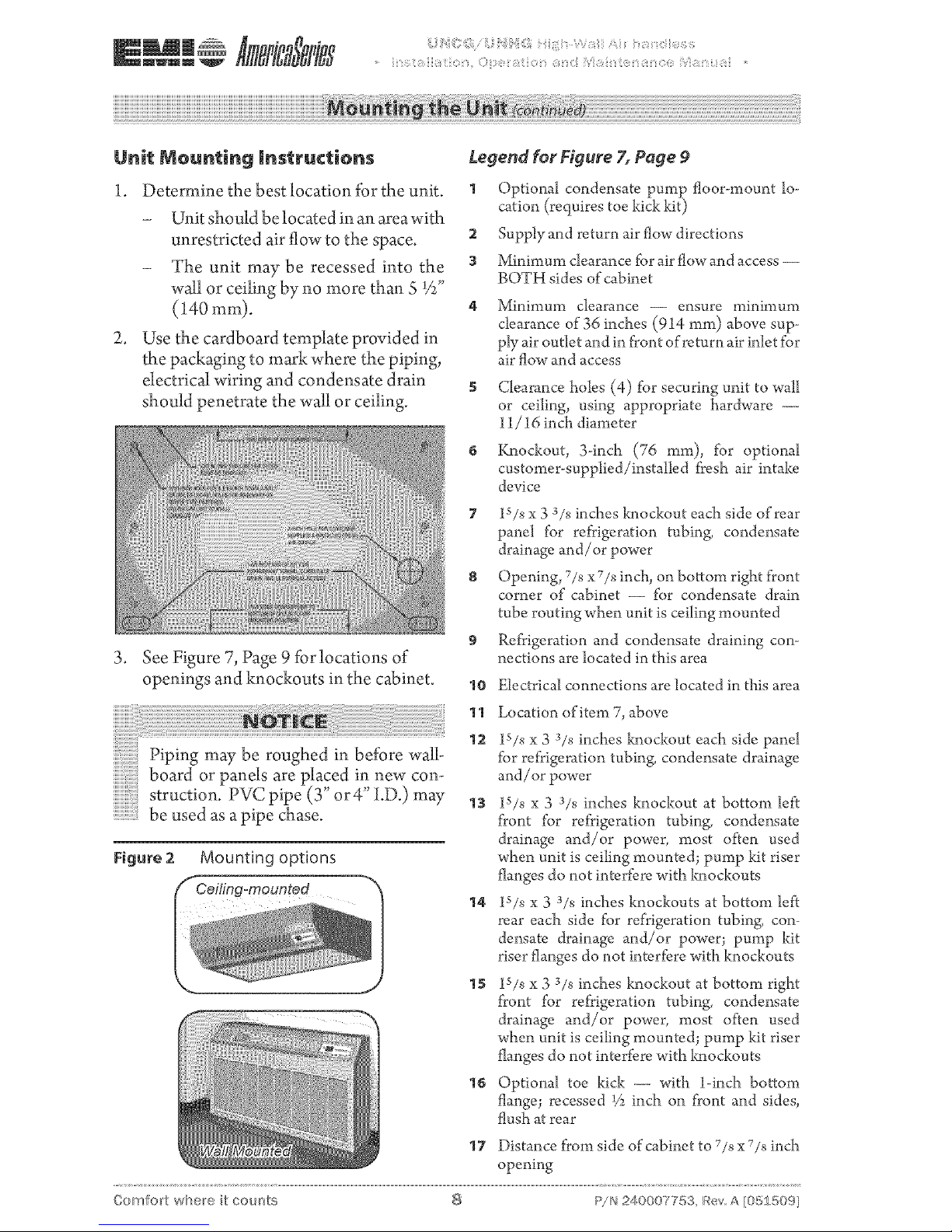
Use the cardboard template provided in
the packaging to mark where the piping,
electrical wiring and condensate drain
should penetrate the wall or ceiling.
Legend for Figure 7, Page 9
1 Optional condensate pumi_ floor-laount lo-
cation (requires toe kick kit)
2 Supply and return air flow directions
3 Minimum clearance for air flow and access --
BOTH sides of cabinet
Minimum clearance -- ensure minimum
clearance of 36 inches (914 ram) above sup-
ply air outlet and in front of return air inlet for
air flow and access
Clearance holes (4) for securing unit to wall
or ceiling, using appropriate hardware --
11/16 inch diameter
Knockout, 3-inch (76 ram), for optional
customer-supplied/installed fresh air intake
device
3.
7 lS/s x 3 3/s inches knockout each side of rear
panel for refrigeration tubing, condensate
drainage and/or power
8 Opening, 7/s x 7/8 inch, on bottom right front
corner of cabinet -- for condensate drain
tube routing when unit is ceiling mounted
9
See Figure 7, Page 9 _k_rlocations of
openings and knockouts in the cabinet, 10
Refrigeration and condensate draining con-
nections are located in this area
Electrical connections are located in this area
Piping may be roughed in before wall-
board or panels are placed in new con-
struction. PVC pipe (3" or4" i.D.) may
be used as apipe chase.
Figure 2 Mounting options
11 Location of item 7, above
lS/s x 3 3/s inches knockout each side panel
for refrigeration tubing, condensate drainage
and/or power
13 lS/8 x 3 3/s inches knockout at bottom left
front for refrigeration tubing, condensate
drainage and/or power, most often used
when unit is ceiling mounted; pump kit riser
flanges do not interfere with knockouts
14 lS/8 x 3 3/s inches knockouts at bottom left
rear each side for refrigeration tubing, con-
densate drainage and/or power; pump kit
riser flanges do not interfere with knockouts
15 lS/8 x 3 3/s inches knockout at bottom right
front for refrigeration tubing, condensate
drainage and/or power, most often used
when unit is ceiling mounted; pump kit riser
flanges do not interfere with knockouts
16 Optional toe kick --- with 1-inch bottom
flange; recessed % inch on front and sides,
flush at rear
17 Distance from side of cabinet to 7/8x 7/s inch
opening
Comfort where it cour_ts 8 P!N24000TT5_, _ev A[05:1_509]
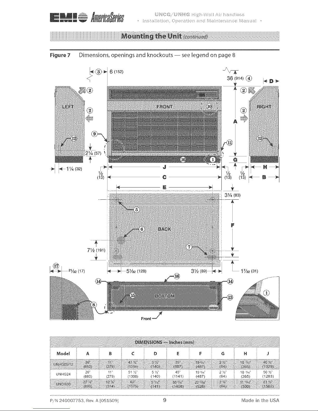
Figure 7 Dimensions, openings and knockouts -- see legend on page 8
36 (914)
r
(13)
3V4(83)
3½
26" 11" 51 ½" 193/16" 2½" 10 7/16" 50 ½"
c
:_/N240007753, RevA[05S50% 9 I"£_adein the UoA
Donotinsta theunitin ocationswhere
curtainsordrapeswillobstructthesup-
pIyairgrille. Thismaycauseairtorecir-
culate without cooling the room, and
mayresult in premature system failure.
4.
S.
6.
Determine the appropriate hole size and
cut through the wall or ceiling.
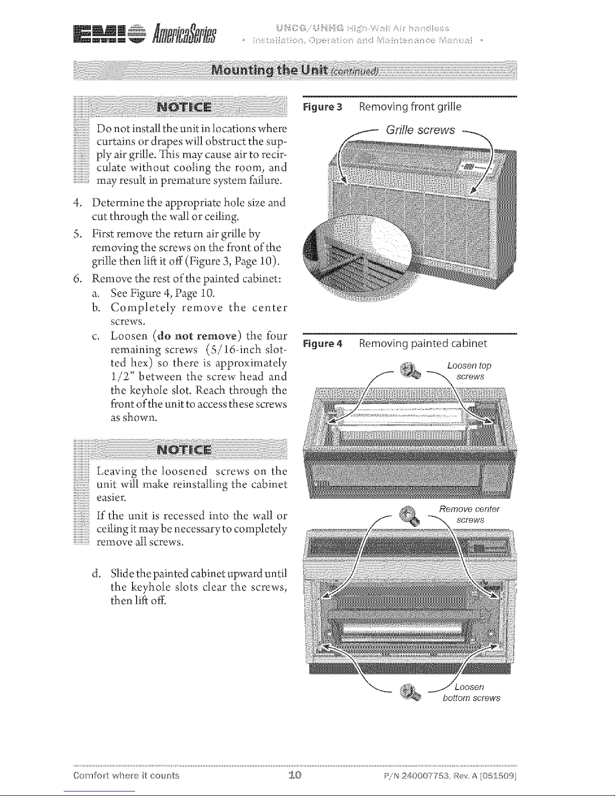
First remove the return air grille by
removing the screws on the front of the
grille then lift it off (Figure 3, Page 10).
Remove the rest of the painted cabinet:
a. See Figure 4, Page 10.
b. Completely remove the center
screws.
c. Loosen (do not remove) the t_ur
remaining screws (S/16-inch slot-
ted hex) so there is approximately
1/2" between the screw head and
the keyhole slot. Reach through the
front of the unit to access these screws
as ShOWn.
iiiiiiiiiiiiiiiiiiii!i!:i i!iiiiiiiii iiiiiiiiiiiiiiiiiiiiiiiiiiiiiiiiiiiiiiiiiiiiiiiiiiiiiiiiiiiiiiiiiiiiiiiiiiiiii!!ii!!ii i ! ! i iii! i !! !! !!i!i!iiiiiiiiiiiiiiiiiiiiiiiiiiiiiiiiiiiiiiiiiiiiiiiiiiiiiiiiiiiiiiiiiiiiiiiiiiiiiiiiiiiiiiiiiiiii!!i!i!i!!i!!i!!i!!i!! i i i i i i i i i i i ! !i ! !!! ! i i i
_!_:_;_:_:_:_:_:_1_Lb_::_:_ '.................................__:_::_
Leaving the loosened screws on the
unitwillmakereinstallingthe cabinet
easier.
If the unit is recessed into the wall or
ceilingitmaybenecessarytocompletely
remove all screws.
d. Slide the painted cabinet upward until
the keyhole slots dear the screws,
then lift off.
Removing front grille
Gri//e screws
Figure 4 Removing painted cabinet
Loosen top
screws
Remove center
screws
bottom screws
Comfort where it cour_ts 1,,,0 P!N 240007753, Bey A :05150%
Replace all panels after installation or
servicing. Panels must remain on the
unit at all times while powered and in
operation.
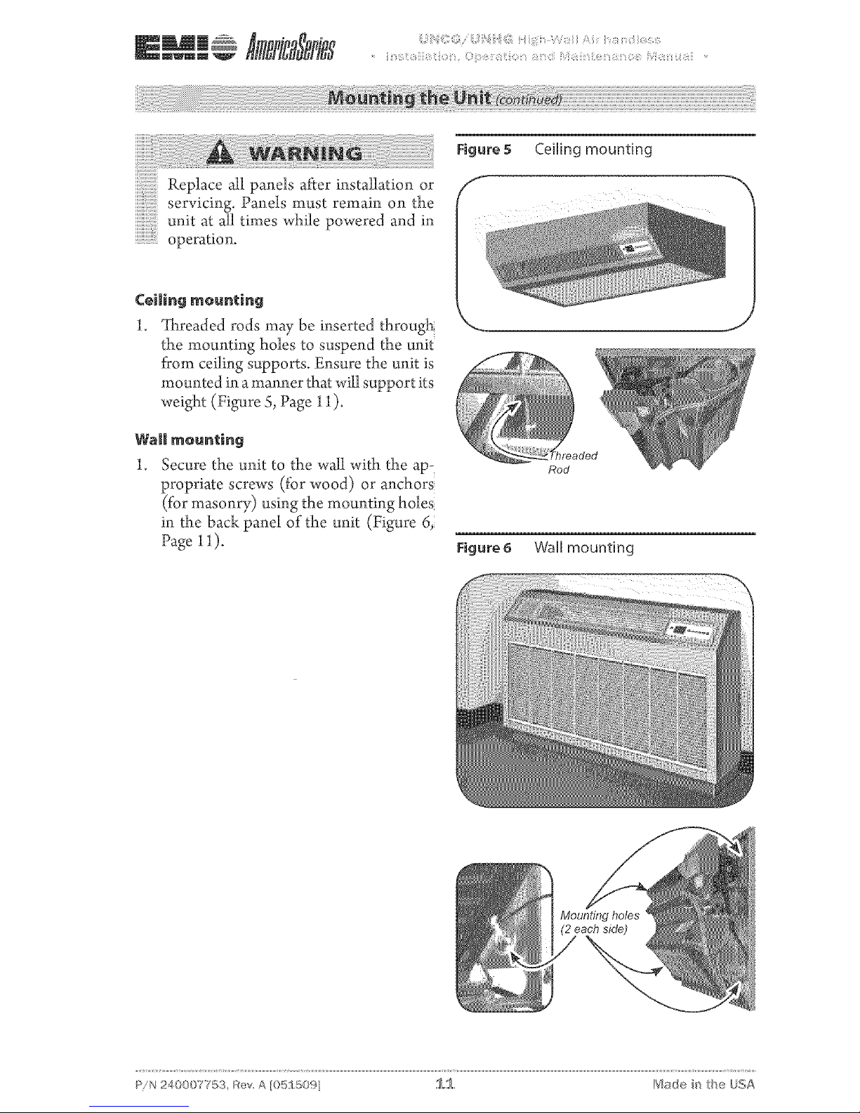
Figure 5 Ceiling mounting
Ceiling meunting
].
_[lareaded rods may be inserted through
the mounting holes to suspend the unit
from ceiling supports. Ensure the unit is
mounted in a manner that will support its
weight (Figure S, Page 11 ).
Wall mounting
1. Secure the unit to the wail with the ap-
propriate screws (for wood) or anchors
(for masonry) using the mounting holes
in the back panel of the unit (Figure 6,
Page 11).
,._ j
Rod
Figure 6 Wail mounting
c
:_/N 240007753, Rev A [05_50% 1,,,1 I"_$adei_ the Uo_A
WWm m _ _ ii !!_!iii;ii_!:iiiii_!:i_:ii0 iii_ Ci_ii:_ii?_i__i!:ii;ii _::_iii_ _i!:ii_'i_:;{ii_fii¸_!i!iii:i_ii::_ilii:i__i;i!i:i_0 _ii_ i_fii¸_!i!i:i_ib_;_ti_ii ....
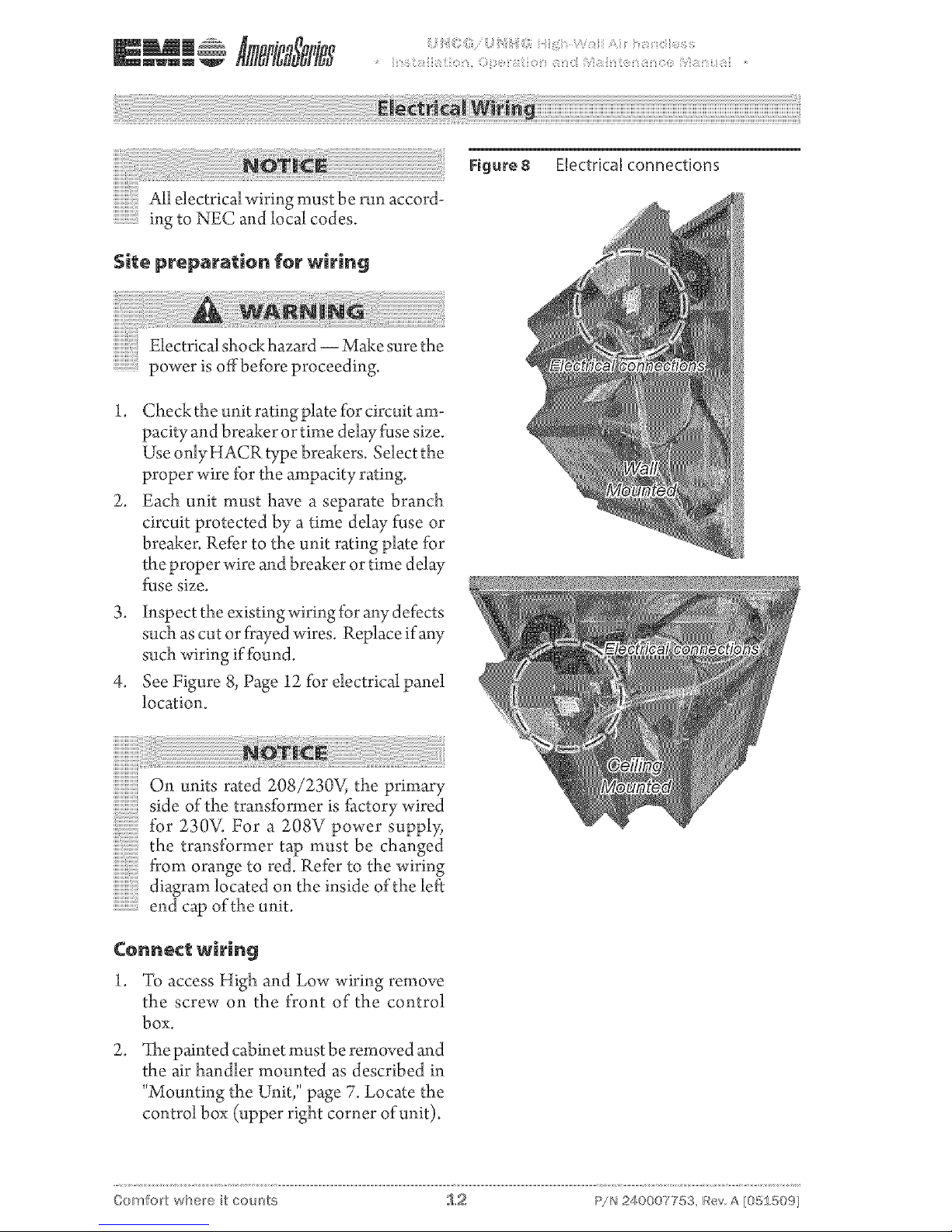
Electrical connections
Electrical shock hazard -- Make sure the
power is offbefbre proceeding.
1. Check the unit rating plate for circuit am-
pacity and breaker or time delay fEse size.
Use onlyHACRtype breakers. Selectthe
proper wire fk_rthe ampacity rating.
2. Each unit must have a separate branch
circuit protected by a time delay fEse or
breaker. Refer to the unit rating plate for
the proper wire and breaker or time delay
fuse size.
3. inspect the existing wiring fbr any defects
such as cut or flayed wires. Replace if any
such wiring if found.
4. See Figure 8, Page 12 for electrical panel
location.
iiiiiiiiiiiiiiiiii
On units rated 208/230V, the primary
sideofthetransfbrmerisfactorywired
fk_r 230V. For a 208V power supply_
the transformertap mustbe changed
from orange to red. Ref)r to the wiring
diagramlocatedontheinsideoftheleft
end cap of the unit.
Ce_e¢_ wiring
1. To access High and Low wiring remove
the screw on the front of the control
box.
2.
_[he painted cabinet must be removed and
the air handler mounted as described in
"Mounting the Unit," page 7. Locate the
control box (upper right corner of unit).
Comfort where it cour_ts 1.2 P!N 240007753, Bey A [05£509]
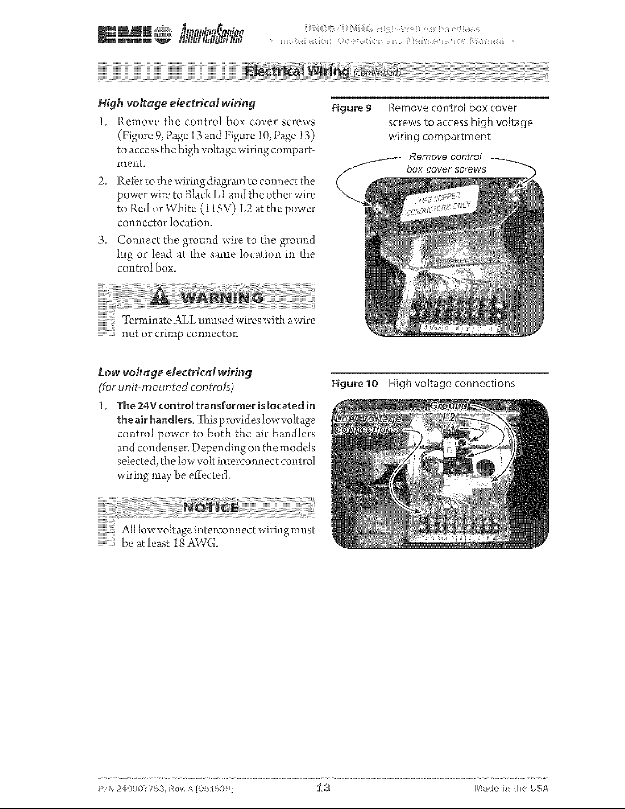
High volfage electrical wiring
1. Remove the control box cover screws
(Figure 9, Page 13 and Figure 10, Page 13)
to access the high voltage wiring compart-
ment.
2.
Refer to the wiring diagram to connect the
power wire to Black L 1 and the other wire
to Red or VVl_ite(11SV) L2 at the power
connector location.
3. Connect the ground wire to the ground
lug or lead at the same location in the
control box.
Figure 9
Remove control box cover
screws to access high voltage
wiring compartment
Remove contro!
box cover screws
Terminate ALL unused wires with awire
nut or crimp connector.
Low voltage electrical wiring
(for unit-moun ted controis)
1. The 24V controJ transformer is located in
the air handlers. _ltxisprovides low voltage
control power to both the air handlers
and condenser. Depending on the models
selected, the low volt interconnect control
wiring ruay be effected.
Figure 10 High voltage connections
All low voltage interconnect wiring must
be at least 18 AWG.
c
:_/N 240007753, Bey A [05_50% 1.3 1"_$8d@ i_ the OoA

Units with or without heat
llowvoltageinterconnectwiringmust
be at least 18 AWG.
Cooling-only
Cooling only units utilize two low volt in-
terconnecting wires between the indoor and
outdoor units.
Wires designated "¥" (yellow) and "C"
(brown) of the air handler should be con-
nected to the corresponding "Y" (yellow)
and "C" (brown) wires or terminals of the
condenser (Figure 11, Page 14).
Other wires or terminals such as "R" (red) or
"O" (orange) may not be needed and should
be protected by a wire nut from making
contact with the iunction box or other metal
surfaces.
Heat pump connection
Heat Pump Connection: In addition to the
"Y" and "C" connections required for cooling!
heat pumps require a reversing valve control
wire "O" (orange) that is energized in the
cooling mode.
Kthe indoor unit has an electric heater! then
a "W" (white) wire connection will also be
needed to energize the indoor electric heat.
Ka remote thermostat is used.
Heat pumps models require an "R" conneco
tion between the indoor and outdoor unit to
provide power to the defrost control board in
the condenser (Figure 12, Page 14).
Figure 11 Unit-mounted controls--
cooling only
Unit mount control configuration
Straight Cool Applications
O.D, UNIT __ ID. UNIT
1 l I (_o WNr _ 1
NOT USED (G) GRN @ I
!
Figure 12 Unit-mounted controls--
heat pump connection, two-
stage heating
F
Unit mount contro/ configuration
Heat Pump Applications
O,D. UNIT LD, UNIT
[ (g) YEL /;;-- 4
NOT USED (gO BLK
** - E/ectric heat o_tion
J
J
Comfort where it cour_ts 1,,,4 P!N 240007753, Bey A [05£509]

Remote thermestat centrols
.............................Unit mount control If the control
iiiiiiiiiii:i:i:i:i:i:i:iis configured for unit mount control
iiiiiiiiiiiiiiiiiiiiiiiii!i!i!!iDON©Tconnectawallthermostatto
the unit.
The 24V control transformer is located in the
air handier unit. 7his provides lowvolt control
power to both the air handler and condenser.
Depending on the models selected, the inter-
connect control wiring may be effected.
Figure13 Remotewall=mounted thermo-
stat configuration --
cooling only
Remote wall mounted thermostat configuration
Straight Cool Applications
O,D, UNIT i.D. UNIT OPTIONAL WALL T'STAT
* - Some thermostats do not
use a "C _ terminal
Choosing a remote wall=mounted
thermostat
See page 33 for wall thermostat control
operation.
Depending on the thermostat required or se-
lected, air handlers may utilize four to six low
volt interconnectingwires between the indoor
unit, thermostat and outdoor unit.
Some thermostats do not require the use of
the "C" (brown) connection. In this case,
ensure that any unused wires are insulated
with a wire nut to prevent them from making
contact with the junction box or other metal
surfaces.
c
:_/N 240007753, Bey, A [05_ 50% 1.5 1"_$sde i_ the Oo,A
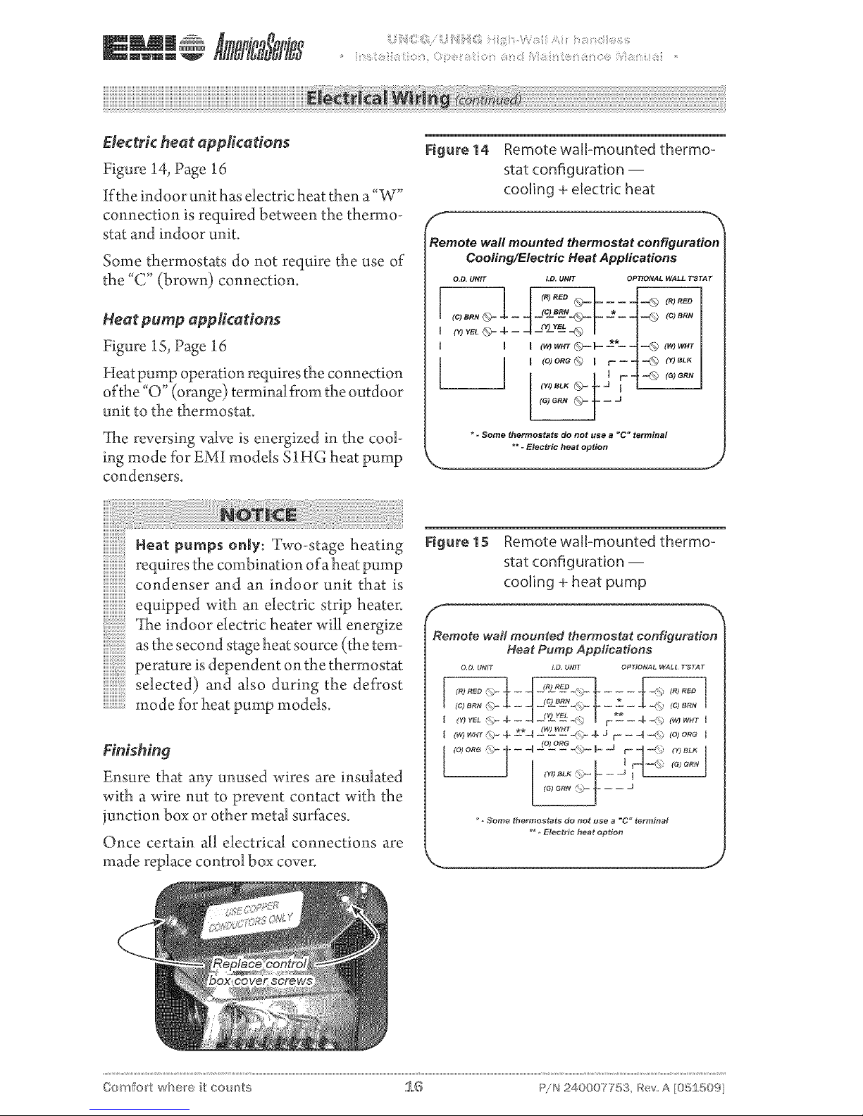
Electric heat applications
Figure 14, Page 16
If the indoor unit has electric heat then a"W"
connection is required between the thermo-
stat and indoor unit.
Some thermostats do not require the use of
the "C" (brown) connection.
Heat pump appfications
Figure 15, Page 16
Heat pump operation requires the connection
ofthe "O" (orange) terminal from the outdoor
unit to the thermostat.
_[he reversing valve is energized in the cool-
ing mode for EMI models SIHG heat pump
condensers.
Figure 14 Remote wall=mounted thermo=
stat configuration --
cooling + electric heat
Remote wall mounted thermostat configuration
Cooling/Electric Heat Applications
O,O. UNIT LD, UNIT OPTIONAL WALL T'STAT
* - Some thermostats do not use a "C" terminal
\ ... ,oot,oooo,opt,oo J
Heat pureps only: Two-stage heating
requires the combination of aheat pump
condenser and an indoor unit that is
equipped with an electric strip heater.
_Ihe indoor electric heater will energize
as the second stage heat source (the tem-
perature is dependent on the thermostat
selected) and also during the de*¥ost
mode for heat pump models.
Finishing
Ensure that any unused wires are insulated
with a wire nut to prevent contact with the
junction box or other metal surfaces.
Once certain all electrical connections are
made replace control box cover.
Figure 15 Remote wall=mounted thermo=
stat configuration --
cooling + heat pump
Remote wall mounted thermostat configuration
Heat Pump Applications
OD UNIT ID UNIT Of_T_ONAt WA_L TSTAT
F -- -- -_ -4\¢ (_ wHr [
I (w) w_T 4 ±*q 2wL_E_<_- 4- J r- - 4 _ to) ore I
* _ Some _hermos_ats do l_ot use a _C _ terminal
** _ Electrfc hea_ option
J
Comfort where it cour_ts 1,,,@ P/N 240007753, Rev A [05250%
 Loading...