

EMI S1CG, S2HG, S1HG, S2CG Installation, Operation And Maintenance Manual
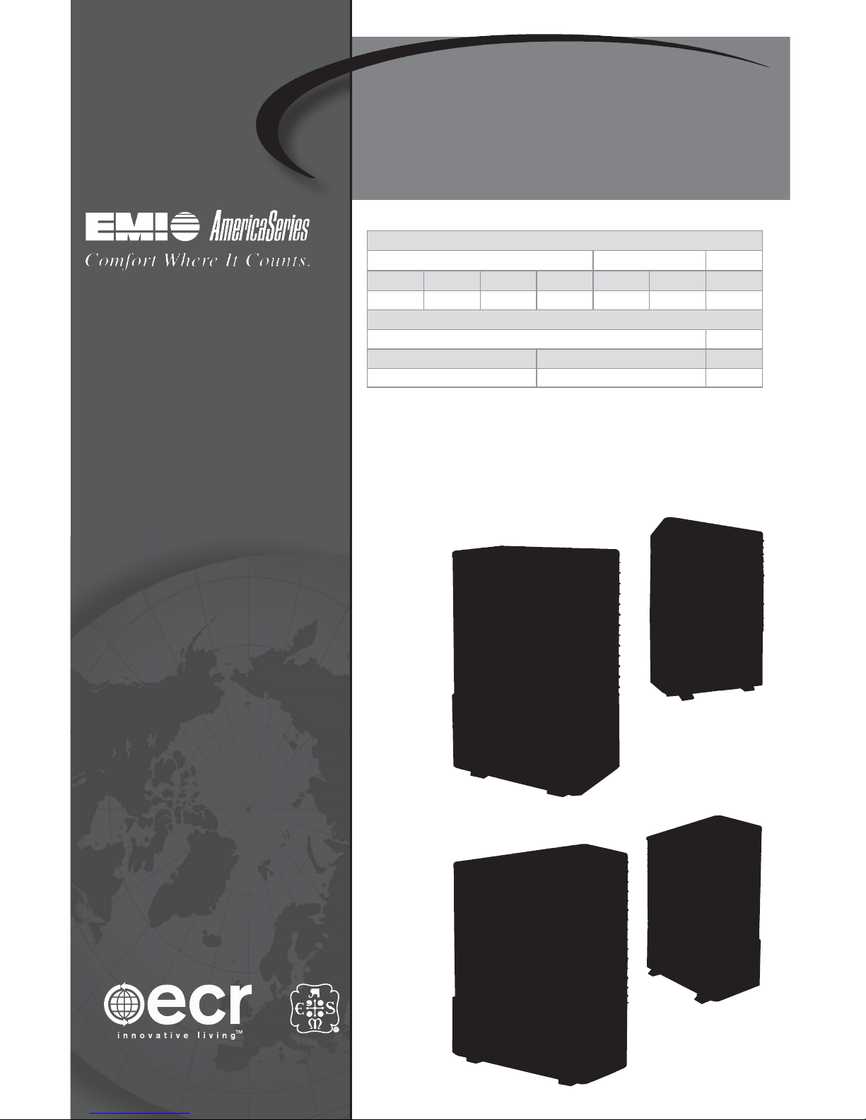
S1CG/S1HG Single-Zone
S2CG/S2HG Dual-Zone
Side-Discharge Ductless Split-System
Condensing Units for R410 Refrigerant
Capacities — Single-Zone Applications
S1CG or S1HG S1CG only
9,000 12,000 18,000 24,000 28,000 33,600 Btuh
2.6 3.5 5.3 7.0 8.3 10.5 kW
Capacities — Dual-Zone Applications
S2CG or S2HG
9,000 12,000 Btuh
2.6 3.5 kW
Installation, Operation and
Maintenance Manual
Units
Units
ECR International LLC
2201 Dwyer Ave
Utica, NY 13504
www.enviromaster.com
S1CG
S1HG
S2CG
S2HG
An ISO 9001-2000 Certified Company
P/N 240007754, Rev. C [3/19/2010]

S1CG/S1HG
Sing
G
nstallation, Operation and Maintenance Manual •
•
le-Zone,
S2CG/S2H
Dual-Zone
Contents
Contents . . . . . . . . . . . . . . . . . . . . . . . . . . . . . . . . . . . . . . . . . . . . . . . . . . . . . . . . . . . . . . 2
Verify unit before installing . . . . . . . . . . . . . . . . . . . . . . . . . . . . . . . . . . . . . . . . . . . . . . . . . . 4
Mounting the Unit . . . . . . . . . . . . . . . . . . . . . . . . . . . . . . . . . . . . . . . . . . . . . . . . . . . . . . . . 6
Electrical Wiring . . . . . . . . . . . . . . . . . . . . . . . . . . . . . . . . . . . . . . . . . . . . . . . . . . . . . . . . . 8
Refrigerant Piping . . . . . . . . . . . . . . . . . . . . . . . . . . . . . . . . . . . . . . . . . . . . . . . . . . . . . . . 11
Refrigerant Processing . . . . . . . . . . . . . . . . . . . . . . . . . . . . . . . . . . . . . . . . . . . . . . . . . . . . 13
Operation Charts . . . . . . . . . . . . . . . . . . . . . . . . . . . . . . . . . . . . . . . . . . . . . . . . . . . . . . . . 17
Starting the Unit . . . . . . . . . . . . . . . . . . . . . . . . . . . . . . . . . . . . . . . . . . . . . . . . . . . . . . . . 30
Operation and Maintenance. . . . . . . . . . . . . . . . . . . . . . . . . . . . . . . . . . . . . . . . . . . . . . . . . 30
Single-zone and Dual-zone Condenser Sequence of Operation . . . . . . . . . . . . . . . . . . . . . . . . . . 31
Single-zone and Dual-zone Condenser Sequence of Operation,
Testing Defrost Operation Using Test Pins . . . . . . . . . . . . . . . . . . . . . . . . . . . . . . . . . . . . . . . . 32
Specifi cation and Dimensions. . . . . . . . . . . . . . . . . . . . . . . . . . . . . . . . . . . . . . . . . . . . . . . . 33
Test Unit Performance Data Sheet . . . . . . . . . . . . . . . . . . . . . . . . . . . . . . . . . . . . . . . . . . . . . 38
EMI’s Product Line . . . . . . . . . . . . . . . . . . . . . . . . . . . . . . . . . . . . . . . . . . . . . . . . . . . . . . . 40
NOTICE
Shipping Damage
Shipping damage MUST be reported
to the carrier IMMEDIATELY.
Examine the exterior. Remove cover
and examine compressor and piping
for signs of damage.
Inspect each component for damage.
Concealed damage must be reported
to the carrier within 15 days of the
receipt of the shipment.
e carrier must make proper notation
on the delivery receipt of all damage
identi ed and complete a carrier inspection report.
e purchaser must notify ECR International’s Customer Service Department of all damage and is responsible
for ling any necessary claims with the
carrier.
Customer Service : (800) 228-9364
To the Installer
Retain this manual and warranty for
future reference. Before leaving the premises, review this manual to be sure the unit
has been installed correctly and run the
unit for one complete cycle to make sure
it functions properly.
To obtain technical service or warranty
assistance during or a er the installation
of this unit, contact your local representative. For a local representative listing, visit
our web site:
www.enviromaster.com
For further assistance call:
1-800-228-9364
When calling for assistance, please have
the following information ready:
Model Number _____________
Serial Number _____________
Date of installation ___________
e EMI series high e ciency condensing unit is backed by EMI and ECR International
and is tested and rated in accordance with AHRI Standard 210/240-2008 and UL-1995.
Due to ongoing product development, product designs and speci cations may change
without notice. Please contact the factory for more information.
Comfort where it counts 2 P/N 240007754, Rev. C [3/19/2010]
NOTICE

S1CG/S1HG
Sing
G
nstallation, Operation and Maintenance Manual •
•
le-Zone,
S2CG/S2H
Dual-Zone
Read Before Proceeding
Recognize this symbol as an indication of
important safety information.
Completely read all instructions
prior to assembling, installing, oper-
ating, or repairing this product.
WARNING
Inspect all parts for damage prior to
installation and start-up. e EMI series
high e ciency condensing unit must be
installed ONLY by quali ed installation
personnel.
Tampering with this unit is danger-
. Tampering voids all warranties. DO
ous
a empt to modify or change this
NOT
DANGER
unit in any way.
Safety Instructions
is manual is intended as an aid to quali ed service personnel for proper installation, operation, and maintenance of the
EMI series high efficiency condensing
unit. Read these instructions thoroughly
and carefully before a empting installation or operation. Failure to follow these
instructions may result in improper installation, operation, service, or maintenance,
possibly resulting in re, electrical shock,
property damage, personal injury, or
death.
Read all instructions before using this
unit. Install or locate this unit only in accordance with these instructions. Use this
unit only for its intended use as described
in this manual.
DANGER
e EMI series must:
Be connected to a properly grounded •
electrical supply with the proper
voltage as stated on the rating plate.
Have proper over current protection •
(i.e. time-delay fuse/HACR Breaker)
as listed on the rating plate.
Failure to follow these instructions can
result in a re, explosion, or electrical
shock causing property damage, personal
injury, or death.
P/N 240007754, Rev. C [3/19/2010] 3 Made in the USA
Check the rating plate on the unit before
installation to make certain the voltage
shown is the same as the electric supply to
the unit. e rating plate is located on the
front panel only.
This unit must be connected only to a
properly grounded electrical supply. Do
not fail to properly ground this unit.
Turn o the electrical supply before servicing the unit.
Do not use the unit if it has damaged wiring, is not working properly, or has been
damaged or dropped.

S1CG/S1HG
Sing
G
nstallation, Operation and Maintenance Manual •
•
le-Zone,
S2CG/S2H
Verify unit before installing
Dual-Zone
Product description
e EMI Series S1CG/S1HG and S2CG/
S2HG condensing units are air-cooled, vertically-arranged side-discharge, high-e ciency
units designed speci cally to meet or exceed
a 13 SEER rating.
e S1CG Models 09–36 and S1HG Models
09–24 condensing units will provide cooling
and heating for a single air handler, as identi ed on page 34 and page 35 .
e S2CG/S2HG 18,000 (99), 21,000 (92)
and 24,000 (22) Btuh capacity condensing
units will provide cooling and heating for two
air handlers, as identi ed on page 36 .
The S1CG/S1HG and S2CG/S2HG are
quiet units that can be recommended for both
commercial and residential applications.
Features
Installation of the S1CG/S1HG and •
S2CG/S2HG condensing units is simpli ed by a 24v control interconnection
from the air handler.
Multiple units can be lined up in close •
proximity to an exterior wall.
Service valves are recessed to reduce •
tampering.
All 9,000-12,000 Btuh units are equipped •
with a Duratec Performance Package that
includes an oversized suction accumulator with surge ba es and enhanced oil
management and a factory-installed solid
core lter drier.
A factory-installed crankcase heater is •
standard on S1HG 09 &12 (thermostatically controlled) and S2HG models, and
is available as optional equipment on
other models.
Controls and components
(Factory-installed or supplied)
Compressor and fan motor contactor•
Run capacitor•
Low voltage terminal connections•
H.P.S. (High pressure switch) with •
manual external reset
Heat pump hard start•
Cooling operation down to 32°F standard •
on all units
Models 09–12 only:•
Large capacity suction accumulator –
Solid-core lter drier –
Thermostatically-controlled crank- –
case heater (heat pump only)
Thermostatically-controlled
crankcase heater
This feature energizes the crankcase •
heater only when needed, saving unnecessary power usage and increasing overall
system e ciency.
Comfort where it counts 4 P/N 240007754, Rev. C [3/19/2010]

S1CG/S1HG
Sing
G
nstallation, Operation and Maintenance Manual •
•
le-Zone,
S2CG/S2H
Verify unit before installing (continued)
Dual-Zone
System options
Corrosion-resistant coil options (sea •
coast and harsh environment usage):
Copper n/copper tube condenser –
coil
Coated aluminum fin/copper tube –
condenser coil
Low Ambient controls for cooling opera-•
tion down to 0°F (standard equipment
can operate down to 32°F)
Optional field-installed kit, when –
speci ed, for cooling operation down
to 0°F — kit includes control, louvers
and wind baffle plus installation
instructions
Low Ambient controls for operation •
down to 0°F (consult factory for availability)
Models 09–12 only:•
115v (single-zone only — S1CG or –
S1HG)
Field-installed thermostatically-con- –
trolled crankcase heater for straight
cool units (S1CG or S2CG) Recommended for operation below 60°F.
Installer-supplied items
Power wiring•
Low Volt wiring (18 awg minimum)•
Secure mounting pad or foundation•
Refrigerant piping (if not purchased from •
EMI)
High Volt Disconnect•
Refrigerant for charging interconnect pip-•
ing (see charge table on page 15 )
NOTICE
Low Ambient controls are required
when the system is asked to cool at
outdoor temperatures below 32°F, this
may cause damage to the compressor
and coil, and may void the warranty. A
field-installed low-ambient kit allows
operation down to 0°F.
This is accomplished by cycling the
condenser fan on and off. This will,
in turn, maintain a constant low-side
pressure, providing a steady cooling
e ect and keeping the air handler from
frosting-up.
e optional kits include louvers/wind
baffle, crankcase heater, outdoor fan
cycling switch, and installation instructions.
P/N 240007754, Rev. C [3/19/2010] 5 Made in the USA

S1CG/S1HG
Sing
G
nstallation, Operation and Maintenance Manual •
•
le-Zone,
S2CG/S2H
Mounting the Unit
Dual-Zone
Before installing, consider:
Locate the unit as close to the indoor sec-•
tion as possible. (see page 11 .)
S1CG/S2CG — If the unit is used for low •
ambient cooling down to 32°F, S1CG/
S2CG require CCH.
Avoid high traffic areas and prevailing •
wind locations.
Surface must be at and level.•
Mount unit above typical snow fall level. •
This is particularly important for heat
pump applications (S1HG/S2HG).
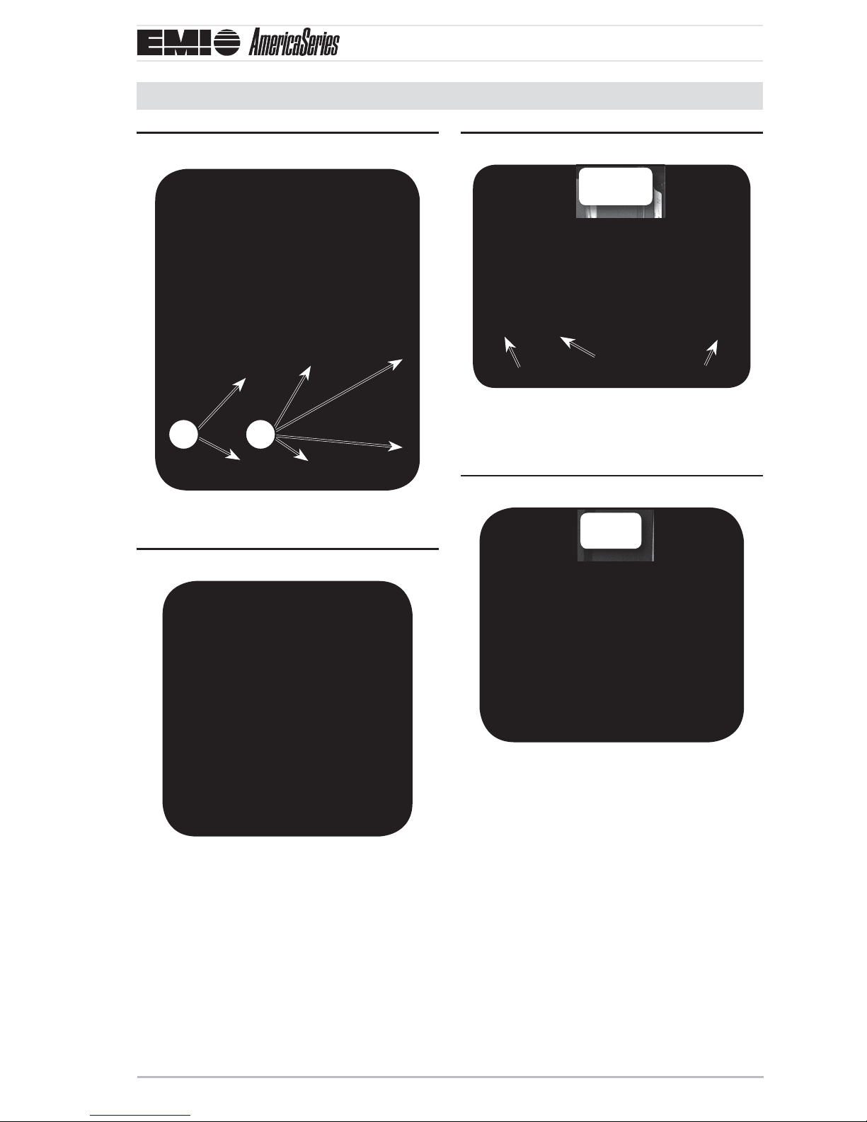
NOTICE
Ensure free ow of air through the •
unit.
Air must not recirculate from dis-•
charge to intake — air is drawn
through the coil and side discharged
through the fan grille.
A minimum 48” clearance is neces-•
sary for the condenser discharge.
Rear intake (coil side) clearance is •
12” minimum.
Consider how power will be run to •
the unit from the power source.
Refrigerant piping should be a direct •
line to the indoor unit.
In areas of heavy snowfall, condensers 2.
should be set above the maximum anticipated snow line (12" is usually adequate
for most locations).
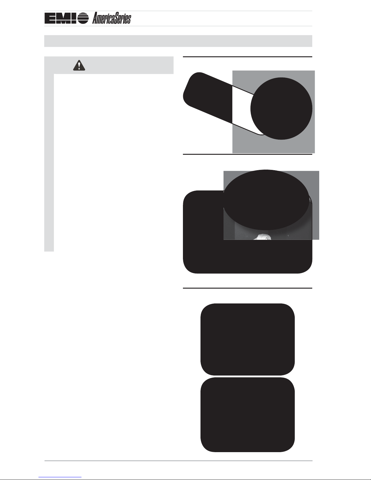
Unit Mounting Instructions
Model S1CG is shown for example in the
following sequence.
e side-discharge unit allows for permanent
mounting through the feet. This is highly
recommended due to the vertical design of
the unit.
1. Figure 1, Page 7 :
Bullet 1 — Loosen the screws on le –
and right sides of the front panel. (Do
not remove these screws.)
Bullet 2 — Remove the screws on the –
front of the panel.
2. Figure 2, Page 7 :
Slide front panel forward to clear side
screws and remove.
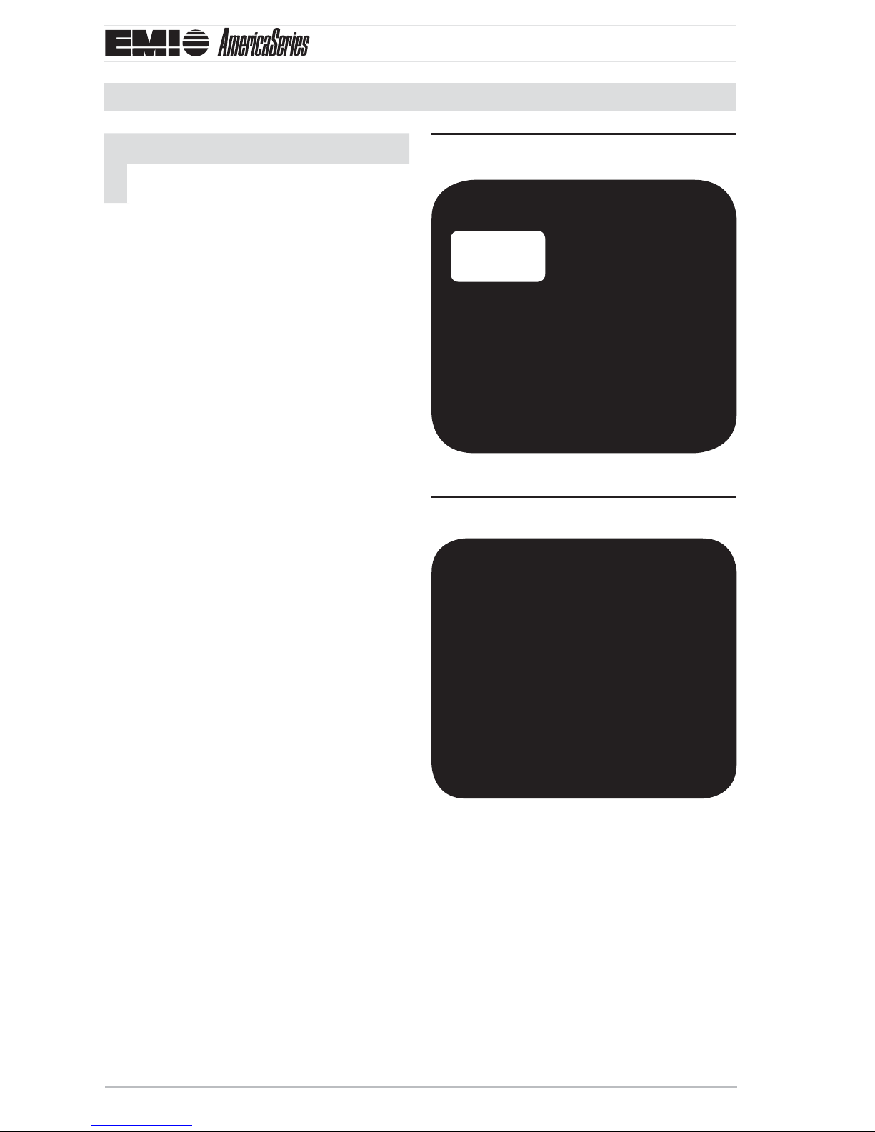
3. Figure 3, Page 7 :
Insert lag bolts through the holes in the
bo om of the unit and tighten to secure.
4. Figure 4, Page 7 :
Insert lag bolts through the holes in the
feet on the back of the unit and tighten
to secure.
Site preparation
Place the unit on a at concrete surface 1.
or pad if on the ground. Roof mounting
should use a built up platform to avoid
intake of hot air from the roof.
Comfort where it counts 6 P/N 240007754, Rev. C [3/19/2010]
Replace the front panel, do not tighten 5.
the side screws at this time.
S1CG/S1HG
Sing
G
A
A
B
C
DDE
S1CG
Shown
S1CG
Shown
nstallation, Operation and Maintenance Manual •
•
le-Zone,
S2CG/S2H
Mounting the Unit (continued)
Dual-Zone
Remove front panel screwsFigure 1
1 2
Bottom lag hole locationsFigure 3
C
A
Lag boltsA Filter drierB
CompressorC AccumulatorD
CapacitorE
S1CG
Shown
B
E
A
Lag holes in feetFigure 4
S1CG
Shown
Remove front panelFigure 2
P/N 240007754, Rev. C [3/19/2010] 7 Made in the USA
S1CG/S1HG
Sing
G
Rating
plate
nstallation, Operation and Maintenance Manual •
•
le-Zone,
S2CG/S2H
Electrical Wiring
Dual-Zone
NOTICE
All electrical wiring must be run according to NEC and local codes.
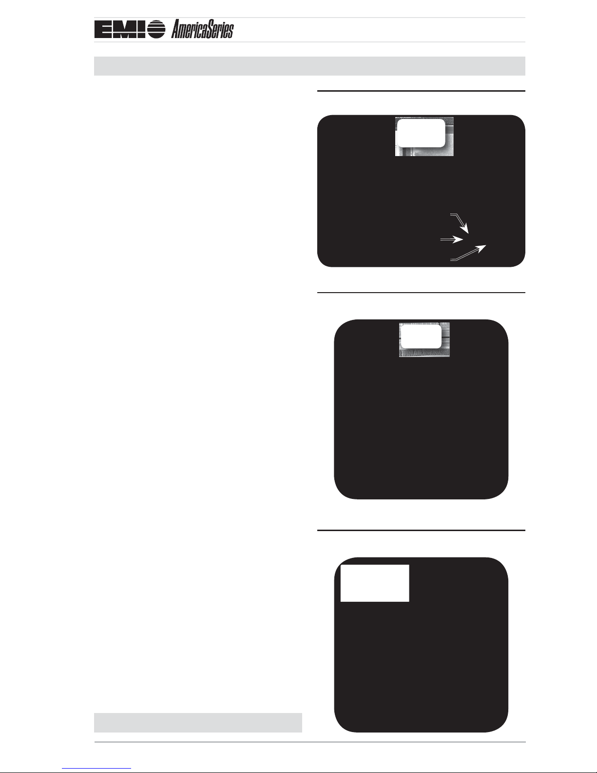
1. Figure 5, Page 8 — Refer to the unit rating plate for voltage, minimum circuit
ampacity and over current protection
requirements.
Use only HACR type breakers or time 2.
delay fuses. Select the wire size according
to the ampacity rating.
To access electrical connections and wir-3.
ing diagram:
a. Figure 6, Page 8 — Remove the
screws on the side panel that covers
the electrical box. e box is adjacent
to the back panel and denoted with
electrical connections.
e screws adjacent to the front panel b.
should already be loose (don’t remove
them).
Slide the side panel out to access the c.
high/low electrical connections and
wire diagram.
d. Figure 7, Page 9 — Add water-tight
strain relief ing to the high volt side
before wiring, a split grommet ing
has been factory installed in the low
volt side.
Rating plate locationFigure 5
Rating
plate
Remove side panel screwsFigure 6
Power should be run to a weather proof 4.
disconnect box usually within 3 feet of
the unit.
Comfort where it counts 8 P/N 240007754, Rev. C [3/19/2010]
S1CG/S1HG
Sing
G
S1CG
Shown
High volt
Plastic edge guards
Low volt
S1CG
Shown
S1CG
Shown
nstallation, Operation and Maintenance Manual •
•
le-Zone,
Electrical Wiring (continued)
S2CG/S2H
Dual-Zone
5. Figure 8, Page 9 — From the disconnect
box, run the power through the 7/8”
hole on the side of the unit and into the
electrical box. Anchor with the strain
relief ing.
Run wires to the high volt pigtail in the 6.
control box and a ach L1 and L2 connections. Also run green wire to ground
wire.
Check wiring diagram for the required 7.
number of low voltage wires to be run
between indoor and outdoor sections.
8. Figure 9, Page 9 — Connect the 24 volt
wiring matching color to color. Refer to
the wiring diagram on the inside panel of
the condenser, and also refer to the wiring diagram on the indoor unit. Low volt
interconnect should be at least 18 awg.
Power entrancesFigure 7
Plastic edge guards
High voltage connectionsFigure 8
S1CG
Shown
Low volt
High volt
S1CG
Shown
See 9. Figure 10, Page 10 and Figure 11,
Page 10 for completed wiring of S1CG
and S2CG examples.
To replace side panel slide the slotted 10.
holes of the panel onto the loosened
screws of the front panel so that the edge
of the front panel covers the edge of the
side panel.
Fasten all remaining loose screws.11.
Low voltage connectionsFigure 9
S1CG
Shown
Continued on next page
P/N 240007754, Rev. C [3/19/2010] 9 Made in the USA

S1CG/S1HG
Sing
G
S1CG
Shown
nstallation, Operation and Maintenance Manual •
•
le-Zone,
Electrical Wiring (continued)
S2CG/S2H
Dual-Zone
Completed wiring, S1CGFigure 10
S1CG
Shown
Completed wiring, S2CGFigure 11
Replacing side panelFigure 12
Fasten loose screwsFigure 13
Comfort where it counts 10 P/N 240007754, Rev. C [3/19/2010]
S1CG/S1HG
Sing
G
nstallation, Operation and Maintenance Manual •
•
le-Zone,
S2CG/S2H
Refrigerant Piping
Dual-Zone
Tubing specifi cations
e system will support refrigerant runs to
the inside unit as listed in
Table 1, Page 11 .
e units are furnished with sweat connections and are equipped with refrigerant valves
and Schrader ings for charging and taking
pressure readings.
CAUTION
It is recommended that a fi lter drier be
installed in the liquid line, at the indoor
unit on models without a factory-installed lter drier (i.e. 18K and larger).
S1CG/S2CG tubing specifi ca-Table 1
tions (see Table 14, Page 11 )
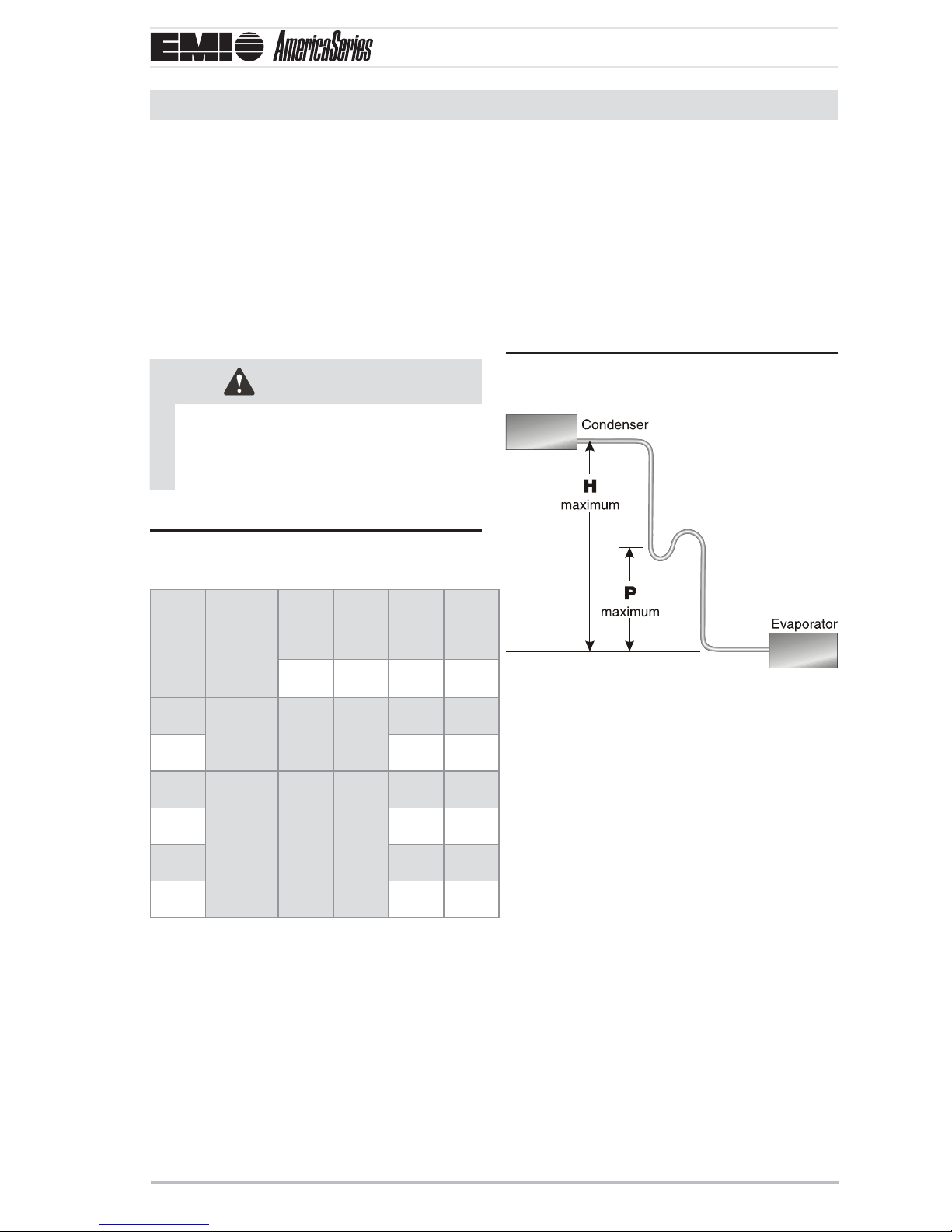
P-trap installation
A P-trap is recommended when the •
suction riser is equal to or greater than
show in Figure 14, Page 11 and Table 1,
Page 11.
When the condenser is installed above the •
air handler, the P-trap will help the return
of oil back to the compressor.
P-trap placement (see Figure 14 Table 1,
Page 11 for dimensions H & P)
Model Max.
Length
Equivalent
Feet
09
12 1/4" 1/2"
18
24 3/8" 3/4"
30 3/8" 3/4"
36 3/8" 3/4"
50’
(15 m)
100’
(30 m)
Max.
Lift
“H” “P” O.D. O.D.
20’
(6 m)
35’
(11 m)
Max.
Trap
Height
15’
(5 m)
20’
(6 m)
Liquid
Suction
Line
1/4" 1/2"
3/8" 5/8"
Line
A P-trap may be fabricated using (2) street •
elbows and (2) regular elbow.
A prefabricated trap may be purchased •
from a wholesaler or distributor however
the trap should be shallow as with the (3)
elbow con guration.
Each elbow is approximately 2 equivalent •
feet.
One P-trap is equal to approximately •
12 equivalent feet.
P-traps are not required at the foot of the •
hot gas risers due to increased oil ow at
higher temperatures.
P/N 240007754, Rev. C [3/19/2010] 11 Made in the USA
S1CG/S1HG
Sing
G
S2CG
S1CG
Shown
S1CG
Shown
S2CG
Shown
nstallation, Operation and Maintenance Manual •
•
le-Zone,
S2CG/S2H
Refrigerant Piping (continued)
Dual-Zone
CAUTION
Avoid piping on wet and rainy days.•
Use only clean, refrigeration-grade •
copper tubing.
Use tubing benders to guard against •
kinking.
Be certain no burrs remain on the •
ings.
Cap ends of lines until ready for con-•
nections.
Be certain that plastic end caps remain •
in place when inserting through wall
openings.
Insulate the suction line.•
Isolate tubing from transmi ing vibra-•
tion to the building or unit and avoid
contact with sharp edges.
Wrap refrigeration valves with a wet •
rag “heat sink” to protect valves while
brazing. (See Figure 16, Page 12 .)
Clean ends of tubingFigure 15
Wet rag “heat shield over valvesFigure 16
S1CG
Shown
S2CG
Refrigerant piping
Clean the ends of tubing and insert into 1.
ings ( Figure 15 ).
Protect valves by wrapping with a wet rag 2.
“heat sink” before brazing ( Figure 16 ).
Use a shield to protect the paint as shown 3.
in Figure 17 . ( e shield can be made
from scrap metal.)
Braze tubing into ings.4.
Install all panels removed to this point. 5.
Panels are required for proper air ow.
Make a shield to protect paintFigure 17
S1CG
Shown
S2CG
Shown
Comfort where it counts 12 P/N 240007754, Rev. C [3/19/2010]
 Loading...