

EMI S1HA4000, S1HA9000, S1CA3000, S1CA2000, S1HA2000 Installation, Operation And Maintenance Manual
...
CACA/CAHA & CACB/CAHB CASSETTE
duCTlESS SpliT SySTEm Air HAndlErS
P/N 240006022 Rev. 1.5 [1/08]
Enviromaster International LLC
5780 Success Dr.
Rome, NY 13440
www.enviromaster.com
installation, operation and maintenance manUal
An ISO 9001-2000 Certied Company
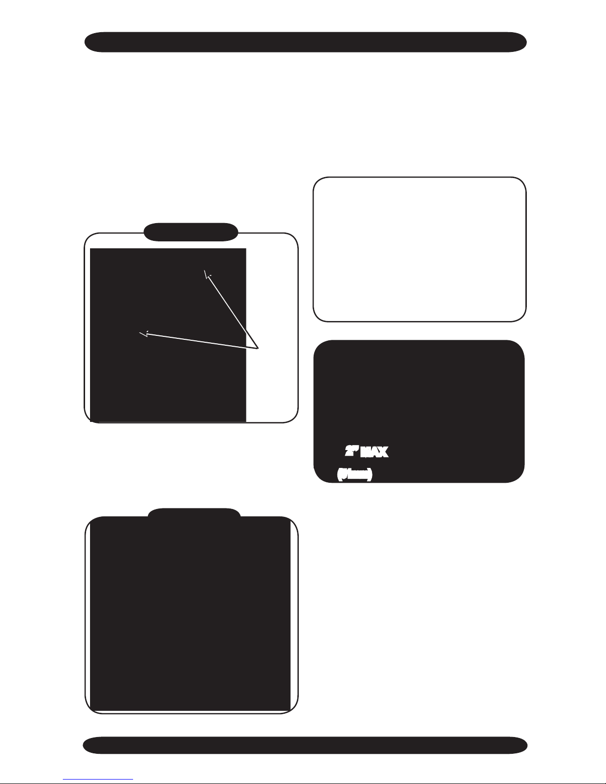
CAHB12
Model Shown
straight cool
Nominal Circuit Capacities:
30,000 - 36,000 Btuh
heat pUmp
Nominal Circuit Capacities:
9,000 - 12,000 - 18,000 - 24,000 Btuh

www.enviromaster.com
3
Cassette Air Handler
TO THE INSTALLER
INSTALLATION, OpERATION ANd mAINTENANCE mANUAL
CASSETTE HIgH EffICIENCy AIR HANdLERS
Shipping Damage MUST be Reported
to the Carrier IMMEDIATELY!!! Examine the exterior.
This manual is intended as an aid to a
qualified service personnel for proper
installation, operation, and maintenance
of EMI AmericaSeries high efciency air
handlers. Carefully read these instructions
before attempting installation or operation.
Failure to follow these instructions may
result in improper installation, operation,
service, or maintenance, possibly resulting
in re, electrical shock, property damage,
personal injury, or death.
SAfETy INSTRUCTIONS
This unit has been designed and manufactured to meet international safety
standards.
Read all instructions before installing
or using the EMI AmericaSeries high
efciency air handlers. Locate and
install this unit only in accordance
with these instructions. Use this unit
only for its intended purpose as described in this manual. Care must be
taken to obtain the best results.
Check the rating plate on the EMI
AmericaSeries air handlers before
installation to make certain the
voltage shown is the same as the
electric supply to the unit.
The EMI AmericaSeries air handlers
must be connected only to a properly
grounded electrical supply. Do not fail
to properly ground this unit.
Turn off the electrical supply before
servicing the EMI AmericaSeries
air handlers. Ensure that there is no
power to any part of the equipment
and both the indoor and outdoor
units are switched off.
Do not use the EMI AmericaSeries
air handlers if it has damaged wiring,
is not working properly, or has been
damaged or dropped.
Follow all safety instructions in this
manual and on any tags or labels
on the unit.
[Save These instructions]
(1) Retain this manual and warranty for future
reference.
(2) Before leaving the premises, review this
manual to be sure the unit has been
installed correctly and run the unit for
one complete cycle to make sure it func-
tions properly.
To obtain technical service or warranty
assistance during or after the installation
of this unit, check our web site @ www.
enviromaster.com or call your installing
contractor or distributor. Our technical
service department may be contacted at
1-800-228-9364.
When calling for assistance, please have
the following information ready:
• Model Number___________________
• Serial Number___________________
• Date of installation________________
Ensure there are no power feeds to the
unit such as re alarm circuits, BMS cir-
cuits, etc.
EMI AmericaSeries Units are
Approved for R-22 Refrigerant ONLY.
! !
WARNING

www.enviromaster.com
Cassette Air Handler
4
STANdARd fEATURES
Continued
pROdUCT dESCRIpTION
The EMI AmericaSeries Cassette Air
handlers are available in three cabinet sizes
with four output capacities from 9,000 24,000 Btuh, and two cooling only capacities
from 30,000 - 36,000 Btuh. Key features
include a condensate pump with safety
switch and a 36” (0.9 m) lift*, electric heat is a
factory installed option ONLY (there are no
,
fresh air inlet and branch duct knockouts,
and motorized air vanes (Cassette 24 & 36
only). The Cassette air handler accepts a
24 volt thermostat control (thermostat not
included). Designed for low noise levels,
easy installation and maintenance and a
slim line fascia, all ensure minimum intrusion
into the conditioned environment.
Due to ongoing product development,
all designs and specications are subject
to change without notice.
* Condensate pump lift measured from
the base or bottom of the unit.
These American made Cassette Air
Handlers produce system SEER’s meeting
or exceeding 13, when matched with EMI’s
S1CA/S1HA single zone, S2CA/S2HA dual
zone side discharge condensing units,
T2CA/T2HA, T3CA/T3HA, or T4CA/T4HA
top discharge multi-zone condensing units.
Refer to specications contained in this
document.
All EMI Air Handlers are backed by
Enviromaster International LLC and are
tested, rated, and certied in accordance
with ARI standards 210/240 and UL 1995.
STANdARd fEATURES
Materials of Construction - Galvanized
steel cabinet with re-resistant thermal
and acoustic foam insulation and light grey
high-impact ABS fascia, and an expanded
polystyrene drain pan with a tough re
retardant thermoplastic liner.
Air Systems:
• Fans are backward curved impeller
centrifugal design; dynamically and
statically balanced; and mounted on
integral mounting rails.
• Single Fan models, Cassette 12 & 24,
are designed with re retardant plastic
or aluminum impellers.
• Twin Fan models, Cassette 36, are
designed with fire retardant plastic
impellers.
• Motors are multispeed, enclosed type
with thermal protection and sealed
lifetime bearings.
• Permanent, washable lter (user accessible).
• Branch duct knockouts on three sides
for remote discharge locations (using no
more than two non-adjacent sides).
• Fresh air intake capability on three sides
of cabinet (only two on the Cassette
12’s).
• Four plastic air vanes; motor driven with
auto sweep or xed position stop setting
on the Cassette 24 and 36 models (Cas-
sette 12’s are equipped with manually
adjusted air vanes).
Coil - Coil is seamless, copper tubing,
arranged in staggered conguration, with
enhanced aluminum ns, tested to 600
psig. The tubes are mechanically expanded
for secure bonding to n shoulder.
Refrigeration Circuit - Units are equipped
with a serviceable xed orice expansion de-
vice and use R22 refrigerant only.
Controls and Components (factory
installed or supplied):
• Connections for 24V remote wall thermostat.
• Custom control board featuring program-
mability, conguration, and multiple modes
of operation. (CACB/CAHB only)
• Controls also feature anti-short cycle
timer, post purge fan relay, and an on
board 30 amp electric heat relay.
• Condensate Pump with 36” (0.9 m) lift
measured from base of unit.
• 24V Transformer.
www.enviromaster.com
5
Cassette Air Handler
STANdARd fEATURES
Continued
CASSETTE CONTROLS ANd COmpONENTS
Continued
Fresh air connection: fresh air may
be introduced to the unit by the addition
of ducts connected to the fresh air knockouts on the Cassette case. Recommend-
ed maximum length 10’ (3m) of 4” (0.1m)
diameter duct. The fresh air volume is ap-
proximately 7-10% of the unit’s published
maximum air ow (if more than 10% make
up air is needed, a fresh air booster fan is
required). Refer to Performance Data sec-
tion of this manual for further information.
The Cassette is best installed in new con-
struction or existing construction with a sus-
pended or false ceiling with enough clear-
ance to accommodate concealing the piping
and electrical connections to the unit.
pREpARATION fOR INSTALLATION
U The Cassette fascia and
main chassis are packaged together for
increased protection.
• Remove the banding straps and lift the
cardboard lid.
• Fascia is packed in bubble wrap and on
top of the chassis (fascia is not attached
to the chassis for shipping).
• Cardboard template is between the
chassis and the fascia (DO NOT throw
template away with packaging!).
• Lift the fascia and template from the box
and set aside.
• Remove the Cassette chassis from the
box utilizing the four corner brackets
for lifting. DO NOT use the drain or refrigerant connections for lifting.
• In order to protect the fascia from dirt
and damage, it should be returned to
the box until it is ready to be installed.
When branch ducting
is to be used, two polystyrene pieces for
blanking off fascia openings are Included
with the fascia packing. Up to two nonadjacent sides may be blanked off.
DO NOT throw the two polystyrene blanking
off pieces out with packaging!
Electromechanical Operation (Stan-
An optional thermostat can be obtained through EMI or your local distributor.
NOTE: make sure the thermostat is suitable for
unit operation (i.e., cooling only, cooling/electric
heat, heat pump.)
Filters: Metal framed lters are tted. These
are reusable and may be vacuum cleaned.
Condensate pump: A condensate
pump is designed to carry water out of
the unit. The pump is xed to a mounting
bracket which can be withdrawn from the
side of the chassis and incorporates an
inspection hole to allow a visual check of
the pump during operation. A oat switch
is tted to stop the cooling action (shut off
the compressor) should the pump become
blocked or fail.
IMpORTANT: Total lift for this pump is 36”
(0.9 m) or less.
Air vanes: Air outlet vanes are manual-
ly adjustable on the Cassette 12’s or driv-
en by an electric motor on the Cassette
24’s and 36’s. Where tted, the motorized
air vanes can be set to auto sweep or can
be stopped in a xed position.
Heating: The Cassette may be tted with
electric heaters which are equipped with
over-temperature limit switches. Consult fac-
tory for available models with electric heat.
System Options:
• Infrared Hand Held Controller
(CACB/CAHB only)
• 24V remote wall thermostat
• Electric Heat (@ 230V)
1.5 kW (Cassette 12’s)
3 kW (Cassette 24’s)
5 kW (Cassette 36’s)

www.enviromaster.com
Cassette Air Handler
6
The Cassette 12 unit has is one grille and one
lter.
BLANkINg Off
Cassette 24 units have two hinged grills that
open in the middle and two lters.
hinge
The fascia discharge slot(s) will need
blanking off when ducts are used to chan-
nel the conditioned air to other areas. The
two polystyrene blanking off strips (pro-
vided) will need to be positioned in the
fascia discharge slots to direct the air to
the ducts.
blanking-off
Pieces
Cassette 12 Unit Shown
The Cassette 36 units have three hinged grills
and three lters.
Cassette 24 Unit
Shown
Cassette 36 Unit Not Shown
If the fascia discharge slot needs blanking off:
1. Remove the inlet grille(s) and lter(s).
2. Once the grille(s) and lter(s) are removed
turn the fascia over so the polystyrene in-
sulation is exposed.
3. Take one of the polystyrene blanking off
pieces and push it into the recess in the
polystyrene fascia insulation.
NOTE: Up to two non-adjacent sides can be
blanked off.
www.enviromaster.com
7
Cassette Air Handler
Important - Replace the existing
piston (before installing the unit) with
the piston supplied in the Kit bag: when a
Cassette 24 air handler is matched with a
T2CA/
T2hA4400, T2CA/T2hA2400, T2CA/T2hA8400, T3CA/
T3hA9240, T3CA/T3hA2240, or T3CA/T3hA9940
condenser which
has a 24,000 Btuh compressor (“4” in the capacity decoding eld) the
piston will need replacement only on the 24,000 btuh zone. *
EMi air handlers units contain the appropriate piston for the model. Refer to this docu-
ment to determine if a change is required based on the condenser rating. if the match is
not listed below no piston change is required. (See chart)
CASSETTE pREpARATION ANd pOSITIONINg
pOSITIONINg
The Cassette installation position should be
selected with the following points in mind:
1. Pipe work, electrical connections, con-
trol box and condensate pump access
panels should be readily accessible.
Refer to the “Cassette Dimensions”
section in the back of this manual for
dimensional drawings.
2. The unit should be positioned at least
5 ft. (1.5m) from a wall or similar obstruction. Position the unit as close to
the center of the room as possible to
insure air is distributed evenly.
3. Position the unit so that the discharge air
does not blow directly on the thermostat.
4. The unit should not be positioned direct-
ly above any obstructions.
5. The condensate drain should have suf-
cient fall 1” per 10’ (8mm/m) in any
horizontal run between Cassette and
drain. Maximum condensate pump lift is
36” (0.9m).
6. There should be a minimum 1”
(25.4mm) clearance above the depth
of the Cassette and the false ceiling
for proper installation, shown below
Figure #1 (see the “Cassette Dimensions” section in the back of this IOM
for cabinet sizing):
Dimension A + 1” = minimum space
above the false ceiling for installation
A
A +1”
Figure #1
model #
Air handlers
Condenser Btuh
factory Installed
Piston-Orice Size
field Changeover
Piston-Orice Size
CAHA / CAHB24
T2CA/T2HA4400
T2CA/T2HA2400
T2CA/T2HA8400
.059” .063”
CAHA / CAHB24
T3CA/T3HA9240
T3CA/T3HA2240
T3CA/T4HA9940
.059” .063”
* “4” in the capacity decoding eld = 24,000 Btuh
Air handlers
pISTON/ORIfICE INSTALLATION INSTRUCTION
Cabinet dimension A
Cassette 12 11.84” (0.3 m) min.
Cassette 24 12.55” (0.32 m) min.
Cassette 36 14.51” (0.37 m) min.
www.enviromaster.com
Cassette Air Handler
8
CASSETTE CHASSIS pOSITIONINg ANd INSTALLATION
Ceiling opening:
• In existing construction, remove enough
ceiling panels to provide clearance space
for mounting unit to ceiling joists.
• Before beginning the installation, inspect
the unit location, test the strength of the
ceiling joists to insure they will support
the weight of the unit.
• Determine mounting method:
- On wooden beams use threaded rods,
washers, and nuts to suspend support
brackets.
- With metal structures, secure threaded
rods on an existing angle or install a
new support angle.
- On newly built concrete slabs secure
threaded rods with inserts and em-
bedded bolts.
- For previously built concrete slabs install
hanging bolts with an expansion anchor.
A template for ceiling cut-out and rod posi-
tions can be found with the Cassette unit.
- Follow local building codes for required
safety cables, braces, etc.
An opening in the false ceiling will have to
be cut to the following sizes:
NOTE: Make sure the ceiling grid is sup-
ported separately from the Cassette. The
ceiling must not be supported by any part of
the Cassette unit, fascia or any associated
wiring or pipe work.
A
A
B
Cabinet A B
Cassette 12
19.50”
(495mm)
22.87”
(581mm)
Cassette 24
29.19”
(740mm)
30.80”
(782mm)
Cassette 36
29.19”
(740mm)
43.06”
(1094mm)
Figure #2
mOUNTINg THE CASSETTE
CEILINg AIR HANdLERS
ELECTROmECHANICAL
THERmOSTAT
An optional thermostat can be obtained
through EMI or your local distributor. In
addition to positioning the Cassette cor-
rectly, it is very important to locate the wall
mounted thermostat in the optimum posi-
tion to ensure good temperature control.
The installation should be selected with
the following points in mind:
1. Position the thermostat approximately
5 ft. (1.5m) above oor level.
2. Avoid external walls and drafts from
windows and doors.
3. Avoid positioning near shelves and cur-
tains as these restrict air movement.
4. Avoid heat sources (direct sunlight,
heaters, dimmer switches, etc.)
5. Seal wiring holes in the wall behind the
thermostat to avoid drafts.
Cabinet Opening Size
Cassette 12
23¼” x 23¼” (591 x 591mm)
Cassette 24
33⅞” x 33⅞” (860 x 860mm)
Cassette 36
46” x 33⅞” (1168 x 860mm)
(51mm x 45°)
2.000 x 45° Typ
Rod
Positions
1.500 Typ
Rod
Positions
(38mm Typ)
www.enviromaster.com
9
Cassette Air Handler
1. Use the template (provided) to cut the
ceiling opening and determining the rod
positions.
2. Install hanger bolts using 3/8” (10mm)
all thread rod at the centers shown in
Figure #2.
3. Prepare the installation guides by fold-
ing the metal bracket by hand along the
perforations, see Figure #3.
INNER CASE
INSULATIoN
CASSETTE
CASE
Figure #4
5. Secure unit in position with locknuts and
washers on either side of the Cassette
bracket.
6. Ensure threaded rod does not protrude
more than 2” (51mm) below the mount-
ing bracket.
4. Lift the Cassette onto the hanging rods.
Level at the correct distance from the
ceiling with the aid of the installation
guides as shown Figure #4.
CASSETTE CHASSIS pOSITIONINg ANd INSTALLATION
Fold
bracket along
perforations
Figure #3
mAx
2”
(51mm)
NOTE: If the ceiling is not level or even, it is
important that the Cassette is installed level to
ensure correct pump operation and to maintain
fan clearances. Place a carpenter’s level on the
unit. A maximum slope of 1/8” (3mm) over the
length of the chassis toward the condensate
drain is allowed. Any slight discrepancy between the Cassette and ceiling will be taken up
by the fascia foam seal.

www.enviromaster.com
Cassette Air Handler
10
fresh Air
Knockout
branch Duct Knockout
Cassette 12
CASSETTE 24 & 36
NOTES: The number of knock-outs varies de-
pending on unit size.
• Branch duct knock-outs are 5¼” (133mm) round
• fresh air knock-outs are
1¼” x 2½” (32 x 64mm)
rectangular on
Cassette 12
and 3” (76mm) square
on
Cassette 24 & 36.
Recommendation: no more than 10’
(3m) of branch duct or fresh air duct should
be installed.
CONdENSATE pIpINg ANd dUCT CONNECTIONS
The unit can now be piped up in ac-
cordance with good refrigeration and/or
plumbing practices.
The Cassette is supplied with a 1/2”
I.D. exible PVC hose for connection to
copper or plastic drain pipework. When
installing the Cassette the following points
should be noted:
1. Maximum pump lift is 36” (0.9m).
2. The highest point in the condensate
pipework should be as close to the unit
as possible. This prevents a large vol-
ume of water draining back into the unit
when it is switched off.
NOTE: There is a check valve at the pump
discharge to prevent water from draining back
into the unit. This piping technique will minimize any issues should the check valve become stuck open from airborne debris.
Correct
Incorrect
Condensate Drain Connection
3. Condensate pipe-work should slope
downwards in the direction of water ow
with a minimum gradient of 1” per 10’
(8mm/1m). There must not be any up-
hill gradients other than in the rst 36”
(0.9m) of pipe-work from the Cassette.
4. When multiple Cassettes are connected
to a common condensate drain, ensure
the drain is large enough to handle the
volume of condensate from several
Cassettes. It is also recommended to
have an air vent in the condensate pipe
work to prevent any air locks.
Duct collars: Branch duct and fresh air
duct collars can be attached to the Cas-
sette chassis by following the steps below:
1. Locating the knock-out holes.
NOTE: A drain line vent may be required to
prevent siphoning of water from the drain pan
and associated noise.
www.enviromaster.com
11
Cassette Air Handler
pIpINg dO’S ANd dON’TS
• Avoid piping on a rainy day.
• Use refrigerant grade copper tubing.
• Use a tubing bender and avoid unneces-
sary bending.
• Cap ends of lines until ready for nal
connections.
Once the unit is mounted and level the Cassette piping connections can be made.
Any change in the diameter of the tubing MUST be
made at the indoor connection. Line-set diam-
eter is determined by the condenser valve size.
Use of a larger line can harm
the compressor!
When matching a the Cassette 24 with an
18,000 Btuh condenser, the interconnecting
suction line needs to be 5/8” O.D. to match
the condenser service valve connection.
Therefore the 3/4” O.D. suction connection
of the Cassette 24 unit needs to be reduced
to 5/8” at the Cassette 24 unit connection to
match the 5/8” line of the condenser.
5/8” bushing goes on suction line
(Only when matched to an 18,000 btuh condenser)
NOTE: Refrigerant and condensate pipes
should be insulated right up to the Cassette
chassis.
The Cassette is equipped with a Flo-
Rater/Piston Expansion device. Connec-
tions are sweat type.
The suction line (large) must be insulated
the entire length with closed cell, foam tube
insulation. Do not insulate the liquid line
(small). Connect the outdoor unit according
to the instructions supplied with unit.
All horizontal piping runs
should be without dips to trap
the oil and slightly inclined, so
as to encourage oil ow in the
direction of the compressor.
Suction line
liquid line
REfRIgERA TION pIpINg
pIpE INSTALLATION NOTES
1. Maximum equivalent pipe run should be no
more than 100’ (30.5m), with a maximum
rise of 35’ (10.7m).
2. Horizontal pipe runs should be slightly inclined,
so as to encourage oil to ow in the direction
of the compressor, for better oil return.
3. Good refrigeration practices must be employed to ensure the correct pressure drop
and good oil return.
2. Cut the black insulation around the
knock-out.
3. Snip the tabs holding the knock-out
in place.
4. Remove the metal knock-out and
the black insulation behind it.
5. Attach the duct collars (eld supplied) to the chassis using self tapping screws. (Repeat steps 1-5 for
remaining duct work.)
CAHB24
CONdENSATE pIpINg ANd dUCT CONNECTIONS
www.enviromaster.com
Cassette Air Handler
12
Assembly Instructions
2. Ensure the white panel fasteners hold-
ing the fascia polystyrene are pushed
rmly in (fasteners may have loosened in
transit).
3. Lift the fascia onto the chassis mounting
bolts. Align the key hole brackets with
the mounting bolts and slide the fascia
forward to lock into position.
1. To install the four fascia mounting bolts:
a) Remove the bolts and washers
from the supplied kit bag.
b) Put washers onto the bolts.
c) Screw the mounting bolt with
washer into the chassis leav-
ing approximately 1” (25mm) to
hang the fascia.
4. On Cassette 24 and 36 units connect
the vane motor plug by plugging it into
the socket connection on the chassis.
a) Ensure that the polarized connector
(2 position) is in the proper orienta-
tion and connected.
b) Route the wires in a way that en-
sures they won’t become trapped,
cut, broken or chaffed.
female vane motor plug on
chassis
Male vane motor plug on fascia
5. ONLY Cassette “B” models (CACB/
CAHB) contain a second cable con-
nection to the control box for the Infra-
red Unit Mount Control.
NOTE: The fascia only ts correctly one way.
Position the fascia so that the AmericaSeries
logo is on the control box end of the chassis.
CASSETTE AIR HANdLER INSTALLATION INSTRUCTIONS

www.enviromaster.com
13
Cassette Air Handler
To complete the installation adjust the louver
position to 30° from plumb, this is recom-
mended for “optimum” system performance.
NOTE: All wiring should be in accordance
with the National Electrical Code (NEC) and
the local building codes.
1.
2. Inspect the existing wiring for any de-
ciencies such as cut or frayed wires.
Replace if any such wiring if found.
The standard unit voltage is 208/230V
(60Hz, 1Ph). Check the unit’s rating plate
for your models’ electrical requirements.
• The wires should be capable of carry-
ing the maximum load current under
non-fault conditions at the stipulated
voltages.
• Avoid large voltage drops on cable runs,
particularly in low voltage wiring.
• The correct cable size must be used to
ensure a voltage drop of less than 1
Volt in the control wiring.
• Once the refrigeration pipe work is
complete, the electrical supply can be
connected.
• Low volt wiring must be at least 18 AWg.
Electrical Wiring
CASSETTE AIR HANdLER INSTALLATION INSTRUCTIONS
a) Ensure that the polarized (10 posi-
tion) connector is in the proper orien-
tation and connected.
6. The fascia can now be tightened up
to the Cassette chassis. M
good seal is obtained between fascia and chassis, this is necessary to
prevent recirculation.
NOTE: Do not over
tighten the bolts. To do so
may cause damage to the
fascia and drain pan.
With lter(s) in place,
the inlet grille(s) can
now be installed onto the
fascia.
b) Route the wires in a way that ensures
that they won’t become trapped, cut,
broken, or chaffed.
Red stripe is
Conductor #1
Polarized
10 Position
Connector
www.enviromaster.com
Cassette Air Handler
14
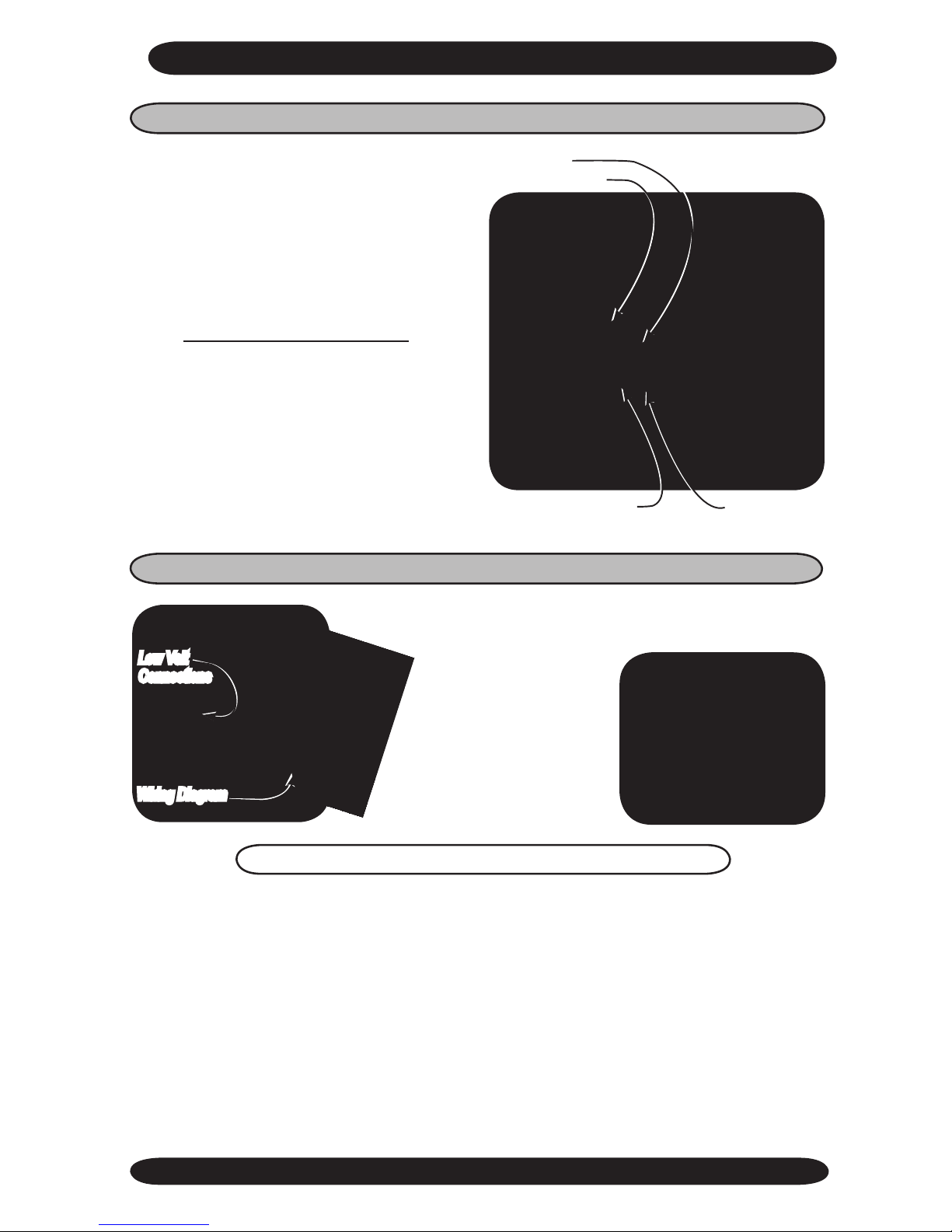
High Volt Electrical Wiring
2. Secure the cable.
3. Refer to the wiring diagram (see follow-
ing page) to connect the ground wire to
the ground lug.
1. Route the cable through the appropriate
hole in the control box for the High Volt
electrical wiring.
high Volt Electric Cable
low Volt Electrical
Connections
CASSETTE AIR HANdLER INSTALLATION INSTRUCTIONS
Electrical Wiring- Continued
4. Slide cover up and out to remove.
5. The rating plate is located on the outside
of control box cover (see low Volt interconnecting Wiring section for location of
wiring diagram).
6. Check the unit rating plate for circuit
ampacity and breaker or fuse size. Use
only HACR type breakers. Select the
proper wire for the ampacity rating.
7. Each unit must have a separate branch
circuit protected by a fuse or breaker.
Refer to the unit rating plate for the
proper wire and breaker or fuse size.
8. It is also recommended that a local dis-
connect switch be connected within 3’
of the unit. In some areas this may be a
code requirement.
3. Remove
the 4 screws
securing the
control box
cover.
www.enviromaster.com
15
Cassette Air Handler
High Volt Electrical Wiring - Continued
Low Volt Interconnect Wiring
Refer to the wiring diagram to connect the low Volt wiring to the
appropriate terminals. The wiring diagram located on
the inside of the control
box cover.
once the connections
are made replace control
box cover with the wiring
diagram facing in and se-
cure with the four screws.
low Volt
Connections
Wiring Diagram
The 24V control transformer is located in the air handler unit. This provides low volt
control power to both the air handler and condenser. Depending on the models selected,
the low volt interconnect control wiring may be different.
NOTE: All low volt interconnect wiring must be at least 18 Awg.
(l1)
(l2)
ground Wire
ground lug
4. Then refer to the wiring diagram to
connect the power wire to (L1) and the
other wire to (L2) at the power connector
location (terminal block).
(See “Electrical Specifications” Section in the back of this manual for more
information.)
Depending on the thermostat required or
selected, cooling only air handlers may
utilize three to ve low voltage intercon-
necting wires between the indoor unit,
thermostat and the outdoor unit. Some
thermostats do not require the use of the
“C” (brown) connection. In this case, en-
sure that any unused wires are insulated
to prevent them from making contact with
the junction box or other metal surfaces.
If the indoor unit has electric heat then a
“W” connection is required between the
thermostat and the indoor unit.
CASSETTE AIR HANdLER INSTALLATION INSTRUCTIONS
www.enviromaster.com
Cassette Air Handler
16
REfRIgERANT pROCESSINg
Finish all pipe connecting before
proceeding to charging the system.
Follow the instructions in the outdoor
unit for line evacuation, opening service
valves, and nal charge adjustments. Op-
eration charts and charge tables can be
found in the EMI Condenser IOMs.
IMpORTANT:
It is illegal to discharge refrigerant into
the atmosphere. Use proper reclaiming
methods and equipment when installing
or servicing this unit.
1. Clean the ends of tubing and insert into
ttings.
2. Protect the valves by wrapping with a wet
rag "heat sink" before brazing.
3. The use of a heat shield is recommend-
ed to protect the paint. (A heat shield
can be made from scrap metal.)
4. Braze tubing into ttings.
5. Attach manifold set.
Refer to Charts in condenser manual to
“ne tune” the refrigerant charge.
heat sink
Shield
S1CA
Shown
Manifold
Vacuum Pump Micron Gage
S1CA
Shown
6. Evacuate line to 500 microns or less to
ensure all moisture has been removed
and there are no leaks.
7. Once certain of a good evacuation and
leak free joints, back-seat the valves
(counter-clockwise) to open and allow fac-
tory charge to ll lines and indoor unit.
 Loading...