

EMI FCP/FHP, CNR, WCP/WHP, CCP/CHP Installation, Operation And Maintenance Manual
TM
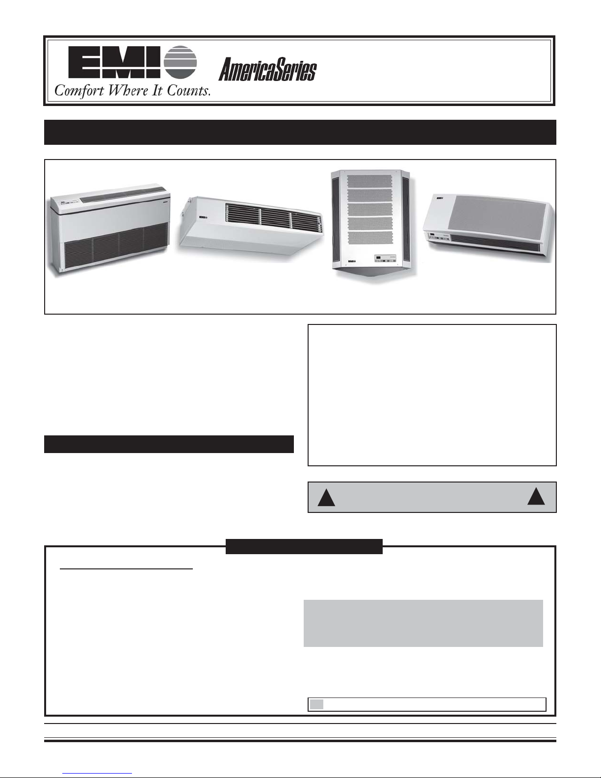
FCP/FHP, WCP/WHP, CNR, and CCP/CHP
P/N# 240-4373, Rev. 1.2 [04/04]
AIR HANDLERS
INSTALLATION, OPERATION, AND MAINTENANCE MANUAL
EMI DUCTLESS SPLIT SYSTEM
FLOOR MODEL AIR
HANDLER (FCP/FHP)
This manual is intended as an aid to qualified service
personnel for proper installation, operation, and maintenance
of the EMI ductless split system floor, wall, corner, or ceiling mounted air handler. Read these instructions thoroughly
and carefully before attempting installation or operation.
Failure to follow these instructions may result in improper
installation, operation, service or maintenance, possibly
resulting in fire, electrical shock, property damage, personal
injury, or death.
CEILING MOUNTED AIR
HANDLER (CCP/CHP)
TO THE INSTALLER
(1) Retain this manual and warranty for future reference.
(2) Before leaving the premises, review this manual to
be sure the unit has been installed correctly and run
the unit for one complete cycle to make sure it functions properly.
TABLE OF CONTENTS
Common To All Air Handlers
Safety Instructions ................................................. 2
Installer Responsibilities ......................................... 2
The EMI Air Handler Family..................................... 2
Installer Supplied Items ........................................... 3
Materials of Construction ........................................ 3
Inspection ............................................................... 3
Items for Consideration ............................................ 3
Controls and Components ....................................... 3
Unit Mount Infrared Control Operation ...................... 3
Optional Controls/Components................................ 3
Electrical Wiring ...................................................... 4
CORNER MOUNTED AIR
HANDLER (CNR)
To obtain technical service or warranty assistance during or after the installation of this unit, call
toll free:
1 – 800 – 228 – 9364
When calling for assistance, please have the
following information ready:
• Model number _____________________
• Serial number _____________________
• Date of installation _________________
RECOGNIZE THIS SYMBOL AS AN INDICATION
!
OF IMPORTANT SAFETY INFORMATION.
Final Installation Checks and Start-up .................. 4-5
Cooling Only Operation and Heat Operation ......... 6-7
Remote Thermostat Operation ............................. 8-9
Floor Model Air Handler (FCP/FHP).................. 10-14
Ceiling Mounted Air Handler (CCP/CHP) .......... 15-16
Corner Mounted Air Handler (CNR) ................... 17-19
Wall Mounted Air Handler (WCP/WHP) ............ 20-22
Maintenance and Troubleshooting .................... 23-26
Test Unit Performance Data .................................. 27
Warranty ............................................................... 28
Specific Unit Installation
WALL MOUNTED AIR
HANDLER (WCP/WHP)
!
The Ductless Split System of Choice
1
www.enviromaster.com
COMMON TO ALL AIR HANDLERS
SAFETY INSTRUCTIONS
WARNING
!
Read all instructions before using the EMI Air Handler. Install or locate this unit only in accordance with
these instructions. Use this unit only for its intended
purpose as described in this manual.
• Check the rating plate on the EMI Air Handler
before installation to make certain the voltage
shown is the same as the electrical supply to
the unit.
• The EMI Air Handler must be connected to a
properly grounded electrical supply. Do not fail
to properly ground this unit.
• Turn off the electrical supply before servicing the
EMI Air Handler.
• Do not use the EMI Air Handler if it has damaged wiring, is not working properly, or has been
damaged or dropped.
!
THE EMI AIR HANDLER F AMILY
The EMI Air Handler is available as a Dx direct expansion straight cool, heat pump – floor, wall, or ceiling units –
and two-pipe chilled water fan coil model. The air handler
offers ease of installation, operation, and service, and can
be matched with EMI’s SCC/SHC single-zone condensing
unit or either of the company’s multi-zone outdoor units,
the MC2/MH2 or MC4/MH4. Presently, EMI does not offer a
chiller unit that provides chilled water for the FCP, WCP and
CCP models.
NOTE: Floor and ceiling units in 42,000 Btuh or
48,000 Btuh capacities must be matched with EMI’s
CCB/CHD condenser.
All EMI Air Handlers are subject to ongoing product development so designs and specifications may change without notice. For more information on a specific air handler,
please refer to the corresponding section in this installation
manual or, for information on EMI Condensing Units, please
visit our website at www.enviromaster.com or contact the
factory for the appropriate literature.
THE EMI DUCTLESS SPLIT SYSTEM AIR
HANDLER FAMILY CONSISTS OF
[Save these instructions]
INSTALLER RESPONSIBILITIES
This manual has been prepared to acquaint you with
the installation, operation, and maintenance of this EMI Air
Handler and to provide important safety information in these
areas.
We urge you to read all of the instructions thoroughly
before attempting the installation or operation of this unit.
This manual should be kept for future reference.
The manufacturer of this unit will not be liable for any
damages caused by failure to comply with the installation
and operating instructions outlined in this manual.
A rating plate identifying this EMI Air Handler can be
found on the unit. When referring to your unit, always have
the information listed on the rating plate readily available.
DANGER
! !
Completely read all instructions prior to assembling, installing, operating, or repairing this product. Inspect all parts for damage prior to installation and start-up. The EMI Air Handler must be installed only by qualified installation personnel.
• FCP: Two-pipe chilled water fan coil floor unit avail-
able in 9,000, 12,000, 18,000, 24,000, 30,000,
36,000, 42,000, and 48,000 nominal Btuh capacities.
• FHP: Dx straight cool/heat pump floor unit, avail-
able in 9,000, 12,000, 15,000, 18,000, 24,000,
30,000, 36,000, 42,000, and 48,000 nominal Btuh
capacities.
• WCP: Two-pipe chilled water fan coil wall unit avail-
able in 9,000, 12,000, 15,000, 18,000, 24,000, and
30,000 nominal Btuh capacities.
• WHP: Dx straight cool/heat pump wall unit available
in 9,000, 12,000, 15,000, 18,000, 24,000, 30,000,
and 36,000 nominal Btuh capacities.
• CNR: Dx Straight cool/heat pump corner unit avail-
able in 9,000, and 12,000 nominal Btuh capacities.
• CCP: Two-pipe chilled water fan coil ceiling unit avail-
able in 9,000, 12,000, 18,000, 24,000, 30,000,
36,000, 42,000, and 48,000 nominal Btuh capacities.
• CHP: Dx Straight cool/heat pump floor unit available
in 9,000, 12,000, 15,000, 18,000, 24,000, 30,000,
36,000, 42,000, and 48,000 nominal Btuh capacities.
All EMI Air Handlers are backed by Enviromaster In-
ternational LLC and are tested and rated in accordance with ARI standards 210/240 and UL 1995.
Made in Rome, New York, USA
2
E-mail: emi@enviromaster.com

INSTALLER SUPPLIED ITEMS
• Low voltage wiring (18 AWG required)
• Power wiring
• Mounting fasteners (screws, wall anchors, etc.)
• Chilled water, condensate, and refrigerant piping
• Refrigerant (for interconnect charge)
MATERIALS OF CONSTRUCTION
1. Cabinet fabricated of 20-gauge galvanneal steel with
an off-white powder coat matte finish
• Plastic tops, fronts constructed of a high impact
Polystyrene (HIPS) material
2. Discharge grill construction of high temperature Noryl
plastic (WHP/WCP and CNR ONLY)
• Annodized Aluminum discharge grill FHP/FCP &
CHP/CCP
3. Condensate drain pan constructed of anticorrosive
G90U galvanized steel
INSPECTION
Upon receipt of the shipment carefully check the shipment against the bill of lading. Make sure all the air handlers have been received. Inspect each unit for damage.
Assure the carrier makes proper notation on the delivery
receipt of all damage identified and that he completes a
Carrier Inspection Report. Concealed damage must be reported to the carrier within 15 days of receipt of shipment.
CONTROLS AND COMPONENTS
Factory Installed or Supplied
Unit mount control panel - standard on FHP/FCP,
WHP/WCP and CNR (optional on CCP/CHP)
• ¾” backlit LCD display
• Adjustable operational range from 55° F to 95° F (in
one-degree increments)
• Anti-short cycle compressor protection
• Minimum compressor run time
• 60 second fan purge
• Freeze protection
• Audio feedback on control setting changes
• Universal control board for straight cool or heat pump
condenser operation
• Two-stage heating w/optional electric heat and heat
pump condenser
• Fan operation: Auto (cycling), High and Low (constant)
• Dry Mode (operates cooling and electric heat simultaneously to remove humidity when optional electric
heat is selected)
• Test Operation for ease of testing after installation
(all timers eliminated)
• Non-volatile Backup Memory (control settings maintained indefinitely during power outages)
IMPORT ANT: Unit mounted controls are fully
functional without the hand-held remote. See page 6
IMPORTANT: It is the responsibility of the pur-
chaser to file all necessary claims with the carrier.
Notify the Enviromaster International traffic department of all damages.
ITEMS FOR CONSIDERATION
• Determine the best location for mounting the unit for
room air circulation. Locate outdoor and indoor units
as close together as possible.
• Determine how power wire (high and low voltage)
condensate drainage, and refrigerant or water supply piping (for chilled water units) may be run to and
from unit. Knockouts on the air handler may be used
for this purpose.
• Determine if the air handler can be accessed for service without obstruction.
• FHP, WHP, CNR, and CHP ONLY: Ensure that in-
terconnect tubing is within the maximum allowable
length of 100’ including a maximum 35’ lift.
• Serviceability should be considered when locating
the unit. The cabinet service panels must be able to
be removed without obstruction.
UNIT MOUNT INFRARED CONTROL
OPERATION
EMI Air Handlers are equipped with a unit mount, infrared compatible control package, optional on the CCP/CHP.
This user friendly, microprocessor control is designed to
optimize system performance and protect the refrigeration
system from unwanted short cycling and evaporator freezeups. Operation of the unit can be made by either the keypad on the unit or by using the optional hand held infrared
controller.
OPTIONAL CONTROLS/COMPONENTS
• Infrared thermostat with hand held remote for CCP/
CHP
• Condensate Pump (field or factory installed)
• Chilled Water Control Valve (field installed)
• Wiring for normally closed/power open valve (24V
AC, 20VA max. or 8VA max. on units with condensate pumps)
• Open wire electric heaters in all size (all with automatic reset high temperature cutout and redundant
high temperature fuse link)
• Hydronic heat coil with sweat connections (consult
factory) FCP/FHP and CCP/CHP only.
The Ductless Split System of Choice
3
www.enviromaster.com
COMMON TO ALL AIR HANDLERS Continued
ELECTRICAL WIRING
(SEE THE APPROPRIATE AIR HANDLER SECTION FOR
All wiring should be in accordance with the National Electric Code (NEC) and the local building codes.
1. Inspect the existing wiring for any deficiencies such
as cut or frayed wires. Replace such wiring if found.
2. Check the unit rating plate for circuit ampacity and
breaker or fuse size. Use only HACR type break-
ers. Select the proper wire for the ampacity rating.
3. Each unit must have a separate branch circuit protected by a fuse or breaker. Refer to the unit rating
plate for the proper wire and breaker or fuse size.
4. Connect the power wire to Black (L1) and the other
wire to Red/White (L2) at the power connector location. Connect the ground wire to the ground lug lead
at the same location in the control box.
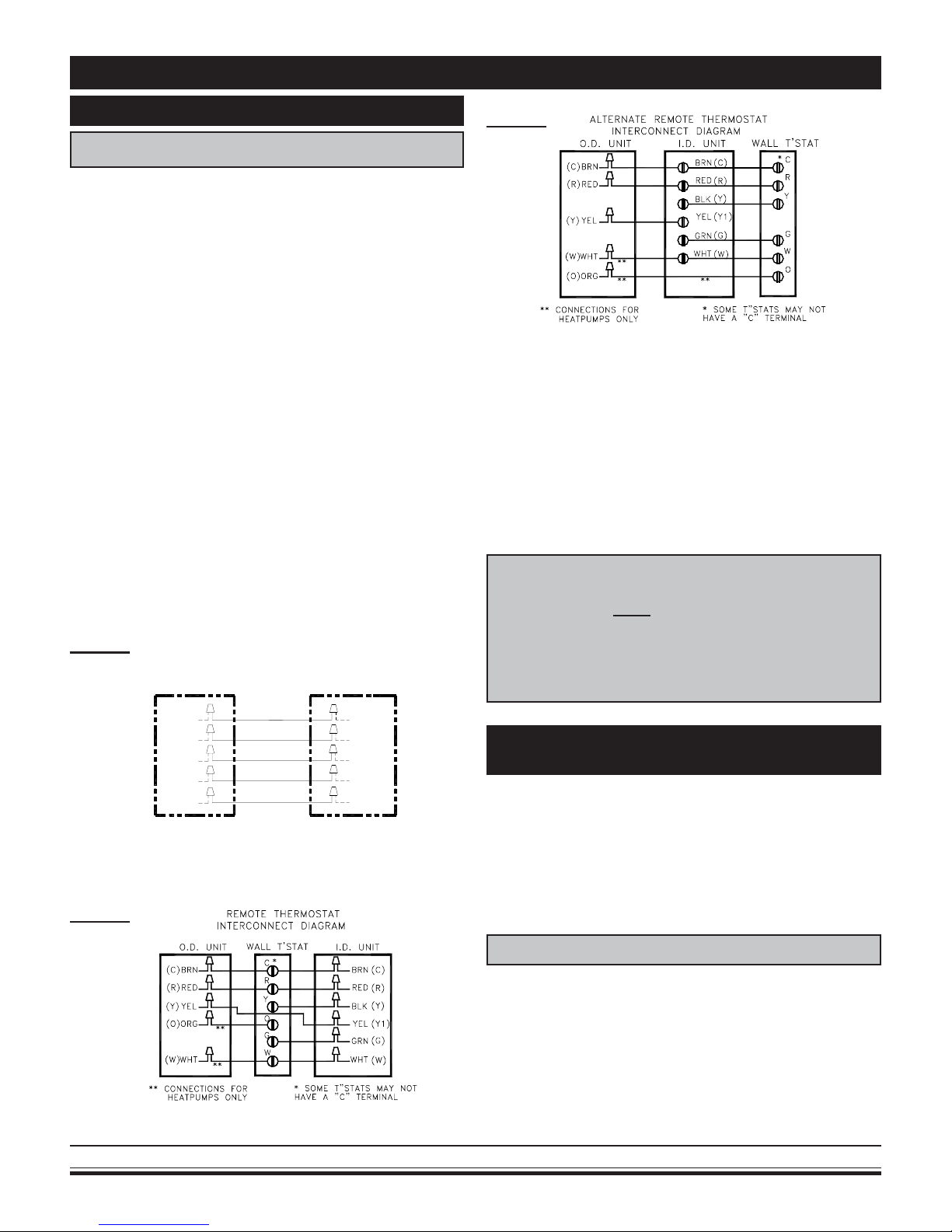
5. Low voltage wiring must be run to the outdoor unit
and thermostat. Refer to the Wiring Diagram on the
unit for details. Be sure to use at least 18 AWG wire.
(Figures 1, 2 or 3)
Figure 1
SPECIFIC WIRING INFORMATION.)
UNIT MOUNT CONTROL
LOW VOLTAGE
INTERCONNECT DIAGRAM
O.D. UNIT
I.D. UNIT
Figure 3
EMI indoor units do not contain a low volt transformer. Low volt power is supplied by a transformer located in the condenser. If using a condenser made by other manufacturers, a low volt
40V A transformer needs to be supplied by the installer.
NOTE: On units rated 208/230V, the primary side
of the transformer is factory wired for 230V . For
a 208V power supply, the transformer tap must
be changed from orange to red.
IMPORTANT: W hen wiring the WHP 18–36 only: If
the job site voltage is 208V , the WHP high-low fan
speed switch must be rewired. Replace the black
and red fan motor wire connections with the blue
and orange fan motor wires respectively.
See unit wire diagram for specific details.
RED
(R)
BRN
(C)
YEL
(Y)
WHT
(W)
ORG(O)
*** CONNECTIONS ONLY
***
***
FOR HEATPUMPS
Figure 2
Made in Rome, New York, USA
RED
BRN
YEL
WHT
ORG
(R)
(C)
(Y)
(W)
(O)
INITIAL START-UP
Unit Mount Controls Only
The unit will start in time delay (unit mount controls
only). These are the default settings of the unit mount I/R
control microprocessor. Once temperature and mode selections have been made, they will be stored in the microprocessor memory when the unit is switched off. The next
time the unit is switched back on via the On/Off switch, the
stored settings will be used and the unit will resume operation.
FINAL INSTALLATION CHECKS
The unit filter must be in place and able to be removed
easily for maintenance. To avoid vibration, check refrigerant lines/chilled water lines to ensure they are not in contact with each other. The unit(s) must be mounted securely
and level.
4
E-mail: emi@enviromaster.com

COMMON TO ALL AIR HANDLERS Continued
START UP
See the “Common” section of this manual (pages 2-8)
for control details.
• Be sure the filter is in place, the unit is level and
separate any lines that contact each other, before
replacing the cabinet front onto the chassis.
Test each power and circuit connection before power-
ing up the system. Use the unit mounted electronic ther-
mostat controls to start the system. (See previous pages
3-8 for operating instructions on Control Operation Section,
Thermostat, unit mount or remote.)
NOTE: Check the outdoor unit’s start-up instructions for specific requirements and procedures.
Operation of the unit depends on the room temperature. It may be necessary to warm the room before testing
the unit’s cooling abilities.
Refer to the specific model of Air Handler for more
detailed installation instructions. (Pages 10-22)
DIP SWITCH SETTINGS
There are two dipswitches on the relay board that offer
different modes of operation. This allows the unit to be
matched with either a cooling only or heat pump condenser.
Dipswitches are factory set for a cooling only condenser. If
the indoor unit is matched with an EMI single zone or multizone heat pump condenser then, the dipswitches will need
to be changed.
WARNING
!
Before accessing the control compartment, disconnect power to both the indoor and outdoor
units. Failure to do so could result in serious injury or electrical shock. DO NOT change dipswitch
settings with power applied to the unit.
To gain access to the relay board, first remove the return air grill from the front of the unit. Then remove any panels or covers to the control section. The relay board is located in the control box of the unit. Set the dipswitches
(Figure 4) according to the table below.
DIP SWITCH SETTINGS
Switch 1 2
Cooling only Open Open
Cooling Elec tric or Hydronic Heat On On
All Heat Pumps Open On
Off = Ope n
!
Once the dipswitches are set and all covers and panels
are replaced, power can be applied to the equipment. When
24V power is applied, the microprocessor will read the
dipswitch setting.
Figure 4
OPEN
DIPSWITCH ON RELA Y BOARD
12
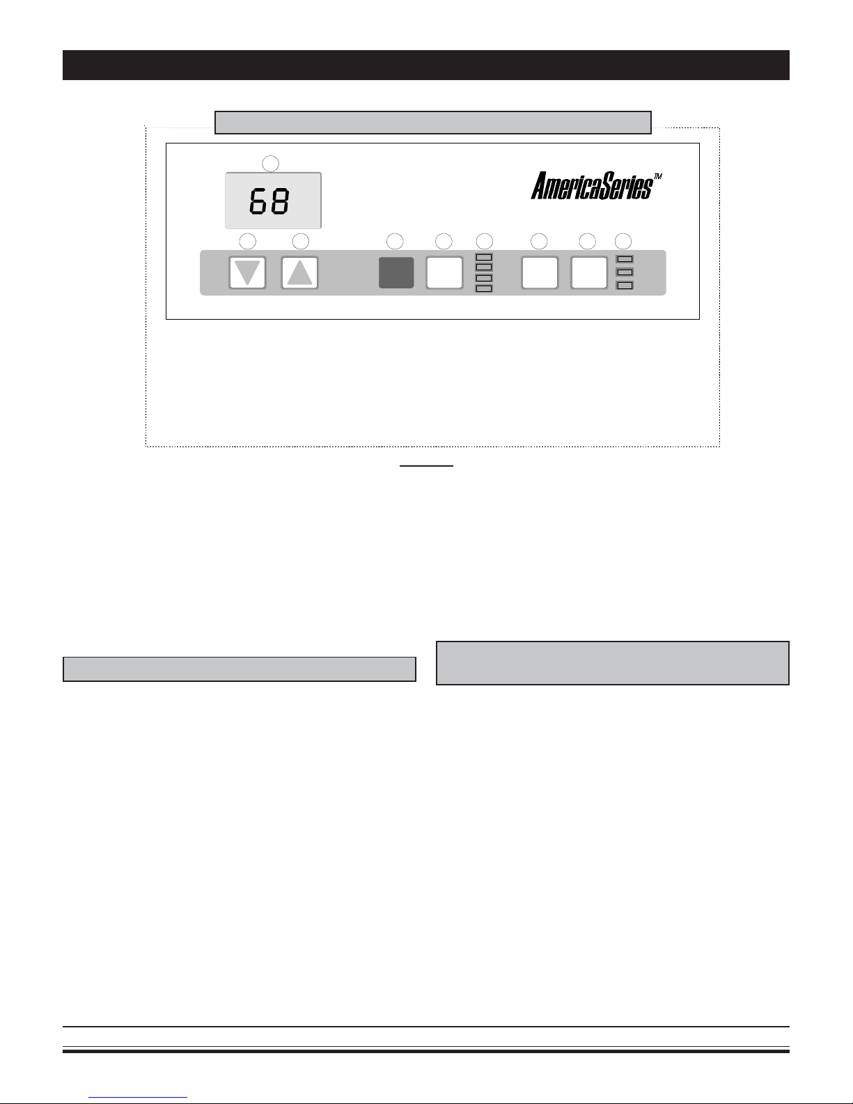
ON/OFF SWITCH
The On/Off switch is used to turn the equipment on or
off. In the off mode the display will be blank and all LED
indicator lights will be dark. To turn on the unit press the
On/off button once. Room temperature will be displayed
and amber LED indicators will show fan speed and mode
selections (Figure 5).
MODE SWITCH
(System Switch)
The Mode button will allow the selection of the desired
mode of operation. Colored LED indicators will light next to
the selected mode. With each successive press of the Mode
button, selection will rotate between Heat, Cool, Fan or
OPEN
12
Dry mode. If the dipswitches are set for cooling only (off –
off) then Heat and Dry will not be accessible (Figure 5).
FAN OPERA TION
The indoor unit utilizes a two-speed motor with three
operational fan modes. The Fan button will allow the selec-
tion of the desired fan setting. An amber LED indicator will
light next to the fan speed selection. If Auto fan mode is
selected then an LED indicator will also light next to Auto.
High and Low are constant fan settings. The fan will
operate continuous regardless of set point or room tem-
peratures. Auto mode is a cycling fan setting.
Auto fan mode can only be selected if the unit is in
Heat or Cool mode. In Auto mode the fan will cycle with
the call for Heat or Cool. Fan speed will be determined by
the microprocessor and speed adjustment will be made
according to room and setpoint temperatures. The fan will
switch to High speed when room temperature deviates by
more than two degrees from setpoint. The fan will switch to
low speed if the deviation is one degree. When the room
temperature reaches setpoint temperature the heat/cool call
will then be dropped. The fan will stay on for an additional
60 sec. to purge unit of any residual energy. After the fan
The Ductless Split System of Choice
5
www.enviromaster.com
COMMON TO ALL AIR HANDLERS Continued
A
UNIT MOUNTED INFRARED COMPATIBLE CONTROL
1
23
1. LCD DIS PLAY
2. TEMP. SET POINT DOWN BUTTON
3. TEMP. SET POINT UP BUTTON
4. INFRARED SENSOR
5. POWER ON/OFF BUTTON
6. MODE INDICATOR LEDS (HEAT, COOL, FAN, DRY)
7. MODE SELECTION BUTTON
8. FAN OPERATION BUTTON
9. FAN INDICATOR LEDS (HIGH - LOW - AUTO)
Figure 5
has been off for ten minutes, the fan will cycle on for 60
seconds. This is done so the microprocessor can sample
the room air and also helps eliminate room temperature
stratification.
When the unit is in Dry mode the fan speed will remain
constant at low speed. While the unit is in Fan mode, Auto
is bypassed and only High or Low are available (Figure 5).
549
6
HEAT
ON/OFF MODE FAN
COOL
FAN
DRY
87
HIGH
LO W
UTO
Once the room temperature is satisfied and the twominute minimum run time has elapsed the compressor will
cycle off. The fan will operate as described in “Fan Opera-
tion” (Figure 5).
NOTE: Once the compressor is switched off there is a
three-minute delay before it will re-start.
COOLING ONL Y OPERA TION
For cooling operation first turn the unit on via the On/off
button. Select Cool mode via the Mode button. The room
temperature will be displayed. Then, by depressing either
the Up or Down arrow once, the setpoint temperature will
appear. The setpoint temperature can then be changed with
each successive press of the Up or Down arrow buttons or
by holding the button in. Place the setpoint temperature
below the room temperature. The compressor will start and
cooling will continue for a minimum of two minutes and as
long as the setpoint remains below room temperature. (On
initial startup or if power is lost, there is a three-minute delay between compressor re-starts.)
Made in Rome, New York, USA
OPTIONAL ELECTRIC HEAT OPERATION
(Non Heat Pump Condenser Units Only)
For electric heat operation first turn the unit on via the
On/off button. Select Heat mode via the Mode button. The
room temperature will be displayed. Then by depressing
either the Up or Down arrow once, the setpoint tempera-
ture will appear. The setpoint temperature can then be
changed with each successive press of the Up or Down
arrow or by holding the button in. Place the setpoint temperature above room temperature. The electric heat will energize and heating will continue as long as the setpoint
remains above room temperature. Once the room temperature is satisfied the electric heat will cycle off. The fan will
operate as described in “Fan Operation” (Figure 5).
6
E-mail: emi@enviromaster.com

COMMON TO ALL AIR HANDLERS Continued
OPTIONAL HEATPUMP WITH
ELECTRIC HEA T
For heat pump operation with backup electric heat, first
turn the unit on via the On/off button. Select Heat mode via
the Mode button. The room temperature will be displayed.
Then, by depressing either the Up or Down arrow once, the
setpoint temperature will appear. The setpoint temperature
can then be changed with each successive press of the Up
or Down arrow or by holding the button in.
Place the setpoint temperature one-degree above the
room temperature. The compressor will start and heating
will continue for a minimum of two minutes and as long as
the setpoint remains above room temperature. Once the
room temperature is satisfied and the two-minute minimum
run time has elapsed, the compressor will cycle off.
(*) On initial startup (or if power is lost) there is a three-
minute delay between compressor re-starts.
(**) Some EMI Heat pump condensers are equipped
with a low temperature cutout that will shut down the condenser and energize the indoor heat. This is designed to
protect the compressor under certain outdoor conditions.
Next, place the setpoint temperature at least two degrees above room temperature. The electric heat will energize along with the compressor (heatpump) thus two-stage
heating. The electric heat will continue to run until the deviation between room temperature and setpoint temperature is less than two degrees. At that time the electric heat
will switch off and the heatpump will take over the heating
demand. Once the room temperature is satisfied and the
two-minute minimum run time has elapsed, the compressor will cycle off. There is then a three-minute delay before
the compressor can restart. The fan will operate as described
in “Fan Operation” (Figure 5).
(2-Stage Heating)
DRY MODE OPERATION
Dry mode will remove humidity from the air while maintaining a specific setpoint temperature. This is done by energizing the compressor in cooling along with the electric or
hydronic heater. Dry mode will not maintain a specific hu-
midity level. The unit must be equipped with an optional
electric heat element or hydronic coil.
For Dry Mode operation first turn the unit on via the On/
off button. Select Dry mode via the Mode button. The room
temperature will be displayed. Then by depressing either
the Up or Down arrow once, the setpoint temperature will
appear. The setpoint temperature can then be changed with
each successive press of the Up or Down arrow or by hold-
ing the button in.
Place the setpoint temperature at a desired room temperature. Depending on the difference between room temperature and set point temperature the compressor and/or
heat source will energize. If the room temperature and
setpoint temperature are the same the compressor will operate in cooling and the electric heat source will also energize.
Should the room temperature fall below the setpoint temperature by two degrees, the compressor will stop and heating will continue to boost the room temperature back up to
stepoint temperature. If the room temperature rises above
the setpoint temperature by two degrees, heating will stop
and cooling will continue to bring the room temperature back
down to stepoint temperature. The fan will operate continuously at low speed while in Dry Mode.
In order to prevent short cycling the minimum on time
for both cooling and heating is two minutes. The minimum
off time is 3 minutes (Figure 5).
UNITS WITH CONDENSATE PUMPS
EMI Air Handlers are available with an optional condensate pump. Condensate pumps are recommended when it
is not possible to gravity drain the condensation from the
indoor unit. Depending on the pump manufacture the maximum lift for the pump will vary. Consult the pump instructions for the maximum lift for the particular pump being used
or refer to specific pump kit information and instructions as
supplied by EMI. (Consult Factory.)
Condensation generated by the evaporator will collect
in the pumps’ reservoir. When the water level is high enough,
a float switch will close and energize the pump motor clearing the water from the reservoir. Should for any reason the
water exceed the maximum preset level, a safety switch
will open, there by interrupting the (Y) signal to the condenser. This will prevent the evaporator from generating more
condensation and spilling out of the unit.
EMI may factory install or supply a detailed field installation kit to follow when pump is purchased as an option
from EMI. (If purchased as an add-on in the field , please
install per manufacturers instructions included with the
pump.
The Ductless Split System of Choice
7
www.enviromaster.com

COMMON TO ALL AIR HANDLERS Continued
REMOTE THERMOSTAT
OPERA TION OPTION
(Standard on CCP/CHP)
INFRARED REMOTE CONTROL OPTION
OPERATIONAL RANGE 55- 90° F (IN 1° INCREMENTS.)
2
1
+
–
3
4
5
SELECTING A THERMOST AT
“Other Than EMI”
When selecting a thermostat other than those offered
by EMI, it is important to choose a 24V thermostat that
matches your application. EMI equipment is compatible with
most mercury bulb, digital or power stealing thermostats.
COOLING ONLY WITH ELECTRIC HEAT OR
HYDRONIC HEAT
Select a thermostat that is compatible with a cooling electric heat system. The thermostat should have “R”, “Y”,
“W” and “G” terminals. The thermostat may also have a “C”
terminal.
HEAT PUMP WITH ELECTRIC HEAT
Select a thermostat that is compatible with a cooling,
two-stage heat, heat pump system. The thermostat should
have “R”, “Y”, “O”, “W (or W2)” and “G” terminals. The thermostat may also have a “C” terminal. If the indoor unit is not
equipped with electric or hydronic heat then a single stage
heat pump thermostat is adequate.
(1) DRY MODE BUTTON
(2) TEMP. SET POINT UP/DOWN BUTTON
(3) POWER ON/OFF BUTTON
(4) FAN SPEED BUTTONS (HIGH - LOW - AUTO)
(5) OPERATIONAL MODE BUTTONS (HEAT - FAN - COOL)
NOTE: BATTERIES INCLUDED.
Figure 6
CHOOSING A THERMOST A T
EMI offers several remote thermostats that are compatible with the Ductless split system air handlers. See the
latest price list for a list of available thermostats. It is important to choose a thermostat that will match the equipment
that you have selected. For single stage cooling or heating
choose a single stage Heat/Cool thermostat. If you have
selected an outdoor heat pump unit and an indoor unit with
electric heat then chose a two-stage heating, single-stage
heat pump thermostat.
FAN OPERA TION
Some thermostats are equipped with an auto/on fan
switch. When this switch is placed in the on position the
indoor fan will run continuous. When the switch is in the
auto position the indoor fan will cycle with the call for heat-
ing or cooling.
FAN PURGE
The indoor unit is equipped an electronic circuit board
with a purge feature. After the room thermostat has been
satisfied, the purge feature allows the indoor fan to remain
on for an additional 60 seconds. This increases efficiency
by pulling the remaining energy from the unit.
Made in Rome, New York, USA
8
E-mail: emi@enviromaster.com

COMMON TO ALL AIR HANDLERS Continued
COOLING OPERA TION
The electronic circuit board of the indoor unit also has
an anti-short cycle timer (ASCT) feature designed to protect the compressor from short cycling. The ASCT is activated immediately following the off cycle of the outdoor unit.
Once the room temperature is satisfied and the outdoor unit
switches off, the ASCT will not allow the outdoor to restart
unit a three-minute time period has elapsed.
After connecting the thermostat to the unit place the
system switch in cool mode. Adjust the set-point tempera-
ture below the room temperature. The compressor and fan
motors will start and cooling will begin. For chilled water
systems, the coldwater valve will open allowing the flow of
water. Place the set-point temperature above the room temperature. The outdoor condenser will stop (or CW valve will
close) while the indoor fan will remain on for an additional
sixty seconds.
ELECTRIC HEAT OPERATION
Place the thermostat system switch in heat mode.
Adjust the set-point temperature above the room temperature. The electric heat will energize along with the indoor
fan motor. Heating will continue so long as the set-point
remains above room temperature. Next place the set-point
temperature below room temperature. The electric heater
will switch off and the indoor fan will remain on for an additional sixty seconds.
HYDRONIC HEAT OPERATION
(Optional On CHP And FHP Units)
An optional hydronic heat package may be selected in
lieu of electric heat. Heating operation is essentially the
same as that of units with electric heat. With the thermo-
stat system switch set to heat and the set-point tempera-
ture above room temperature, the hydronic valve will open
allowing water to flow through the coil. The indoor fan will
also switch on and warm air will flow from the unit. Heating
will continue so long as the set-point remains above room
temperature. Place the set-point temperature below room
temperature. The hydronic valve will close and indoor fan
will switch off after the sixty-second purge time has elapsed.
Units with an optional hydronic heat coil or chilled water coil are also equipped with a freeze protection thermostat. The freeze protection thermostat is designed to protect the hydronic coil or chilled water coil from freeze up
due to abnormally cold fresh air from the fresh air system or
from abnormally cold air from the evaporator coil. Should
the freeze sensor activate, the indoor fan will switch off to
eliminate the source of cold fresh air, and also the outdoor
condenser
unit will be switched off eliminating cold air from the refrigeration system. For units with a hydronic hot water valve
installed, the valve will be energized allowing warm water to
flow and assist in the defrost process. The system will remain in this state until the freeze condition is satisfied whereby the freeze thermostat will reset.
HEAT PUMP
(Cooling Mode)
Cooling operation in a heat pump unit is described in
“Cooling operation” above. Heatpump condensers are
equipped with a reversing valve that is energized for cooling
and de-energized for heatpump mode.
OPTIONAL HEAT PUMP WITH
ELECTRIC HEAT
(2-Stage Heating)
The electronic circuit board of the indoor unit also has
an anti-short cycle timer (ASCT) feature designed to protect the compressor from short cycling. The ASCT is activated immediately following the off cycle of the outdoor unit.
Once the room temperature is satisfied and the outdoor unit
switches off, the ASCT will not allow the outdoor to restart
unit a three-minute time period has elapsed.
After connecting the thermostat to the unit place the
system switch in heat mode. Adjust the set-point tempera-
ture above the room temperature. The compressor and fan
motors will start and heating will begin. Depending on the
thermostat selected, electric heat will also energize when
the deviation between room temperature and set point temperature is greater than two degrees. (See the thermostat
owner’s manual for this feature) Place the set-point temperature below the room temperature. The outdoor condenser
and electric heat will stop while the indoor fan will remain on
for an additional sixty seconds.
The Ductless Split System of Choice
9
www.enviromaster.com
 Loading...