

EMI enviroair szi ZWHA, enviroair szi ZHA, enviroair szi ZWHB, enviroair szi ZHB Operation Manual
Presents
SZI Series
Single Zone ~16SEER High-Wall
Ductless Inverter Split Systems
Installation, Operation &
Manintenance Manual
Air Handler (Indoor) Models: ZWHA/ZWHB
Condenser (Outdoor) Models: ZHA/ZHB
ECR International, Inc.
2201 Dwyer Avenue • Utica, New York 13501
Phone: 800.325.5279 • Web: enviromaster.com
An ISO 9001-2008 Certied Company
PN 240009907, Rev C [01/13/2014]

1
CONTENTS
SAFETY PRECAUTIONS
Warning ...........................................................................................................................................2
Caution ............................................................................................................................................3
INSTALLATION INSTRUCTIONS
Selecting installation place...............................................................................................................4
Accessories .....................................................................................................................................5
Indoor unit installation......................................................................................................................6
Outdoor unit installation ..................................................................................................................8
REFRIGERANT PIPE CONNECTION
Refrigerant pipe connection ............................................................................................................9
ELECTRICAL WORK
Electrical work .................. .............................................................................................................10
TEST RUNNING
Test running ..................................................................................................................................15
AIR PURGING
Air purging with vacuum pump ......................................................................................................13
Safety and leakage check .............................................................................................................13
SOCIABLE REMARK
SAFETY PRECAUTIONS
OPERATING INSTRUCTIONS
CARE AND MAINTENANCE
OPERATION TIPS
TROUBLESHOOTING TIPS
Sociable remark...........................................................................................................17
Warning ......................................................................................................................18
Caution ......................................................................................................................19
Parts names ........... ...................................................................................................20
Special functions ........................................................................................................21
Operating temperature................................................................................................22
Manual operation ........................................................................................................22
Airflow direction control ...............................................................................................23
How the air conditioner works .......................................................................................24
Care and maintenance ...............................................................................................25
Operation tips ............ ...............................................................................................27
Troubleshooting tips ..................................................................................................29

2
Inside you will find many helpful hints on how to install and test the air conditioner properly.
Contact an authorised service technician for repair or maintenance of this unit.
Contact an authorised installer for installation of this unit.
This appliance is not intended for use by persons(including children) with reduced physical, sensory
or mental capabilities, or lack of experience and knowledge, unless they have been given supervision
or instruction concerning use of the appliance by a person responsible for their safety.
Children should be supervised to ensure that they do not play with the appliance.
If the power cord is to be replaced, replacement work shall be performed by authorised personnel only.
Installation work must be performed in accordance with the national wiring Standards by authorised
personnel only.
CAUTION
Read This Manual

3
SAFETY PRECAUTIONS
WARNING
Read the follow SAFETY PRECAUTIONS carefully before installation.
Electrical work must be installed by a licensed electrician. Be sure to use the correct rating
and main circuit for the model to be installed.
Incorrect installation due to ignoring of the instruction will cause harm or damage.
The seriousness is classified by the following indications.
of the power plug
This symbol indicates the possibility of death or serious injury.
The items to be followed are classified by the symbols:
Symbol with background white denotes item that is PROHIBITED from doing.
CAUTION
This symbol indicates the possibility of injury or damage to property.
WARNING
1) Engage dealer or specialist for installation. If installation done by the user is defective, it will cause water
leakage, electrical shock fire.
2) Install according to this installation instructions strictly. If installation is defective, it will cause water
leakage, electrical shock fire.
3) Use the attached accessories parts and specified parts for installation. otherwise, it will cause the set to fall,
water leakage, electrical shock fire.
4) Install at a strong and firm location which is able to withstand the set s weight. If the strength is not enough
or installation is not properly done, the set will drop and cause injury.
,
5) For electrical work, follow the local national wiring standard, regulation and this installation instructions. An
independent circuit and single outlet must be used. If electrical circuit capacity is not enough or defect found
in electrical work, it will cause electrical shock fire.
6) Use the specified cable and connect tightly and clamp the cable so that no external force will be acted on
the terminal. If connection or fixing is not perfect, it will cause heat-up or fire at the connection.
7) Wiring routing must be properly arranged so that control board cover is fixed properly. If control board cover
is not fixed perfectly, it will cause heat-up at connection point of terminal, fire or electrical shock.
8) When carrying out piping connection, take care not to let air substances other than the specified
refrigerant go into refrigeration cycle. Otherwise, it will cause lower capacity, abnormal high pressure
in the refrigeration cycle, explosion and injury.
9) Do not modify the length of the power supply cord or use of extension cord, and do not share the
single outlet with other electrical appliances. Otherwise, it will cause fire or electrical shock.
CAUTION
1) This equipment must be earthed and installed with earth leakage current breaker. It may cause electrical
shock if grounding is not perfect.
2) Do not install the unit at place where leakage of flammable gas may occur. In case gas leaks and
accumulates at surrounding of the unit, it may cause fire.
3) Carry out drainage piping as mentioned in installation instructions. If drainage is not perfect, water
may enter the room and damage the furniture.

4
INSTALLATION INSTRUCTIONS
Selecting installation place
Select an installation location which is rigid and strong enough to support or hold the unit, and select a
location for easy maintenance. Read completely, then follow step by step.
Indoor unit
Do not expose the indoor unit to heat or steam.
Select a place where there are no obstacles in front
or around the unit.
Make sure that condensation drainage can be
conveniently routed away.
Do not install near a doorway.
Ensure the spaces indicated by arrows from the
wall ceiling or other obstacles.
A place where noise prevention is taken into consideration.
A place 1m or more to TV or radio instrument.
A place where air circulation in the room is good.
There should not be any direct sunlight. Otherwise, the sun
will fade the plastic cabinet and affect its appearance. If
unavoidable, sunlight prevention should be taken into considenation.
Outdoor unit
If an awning is built over the outdoor unit to prevent
direct sunlight or rain exposure, make sure that heat
radiation from the condenser is not restricted.
Keep the spaces indicated by arrows from wall or
other obstacles.
Do not place animals and plants in the path of the
air inlet or outlet.
Take the air conditioner weight into account and
select a place where noise, vibration and hot air
discharged will not be an issue.
Do not install in a place full of machine oil or sulfide
gas such as hot-spring resort.
Do not install in a saline place such as coast.
Do not install in a place where there are high frequency
machines such as wireless equipment, welding
machine or medical facility.
If the outdoor unit is installed on a roof structure, be sure to level the unit.
Ensure the roof structure and anchoring method are adequate for the unit location.
Consult local codes regarding rooftop mounting.
Rooftop installation:
Level gauge
Screwdriver
Electric drill,Hole core drill ( 65mm)
Flaring tool set
Specified torque wrenches: 1.8kgf.m,
4.2kgf.m, 5.5kgf.m, 6.6kgf.m
(different depending on model No.)
Spanner (half union)
Tools needed for installation:
Hexagonal wrench (4mm)
Gas-leak detector
Vacuum pump
Gauge manifold
Users manual
Thermometer
Multimeter
Pipe cutter
Measuring tape
Fig.1
More than 30cm
M
ore th
an 6
0cm
More than 30cm
More than 200
cm
Fig.2
More than 2.4m
(from the floor)
More than 15cm
(to the ceiling)
More than
12cm
More than
12cm
Front
Left
Right
B
a
ck
5
INSTALLATION INSTRUCTIONS
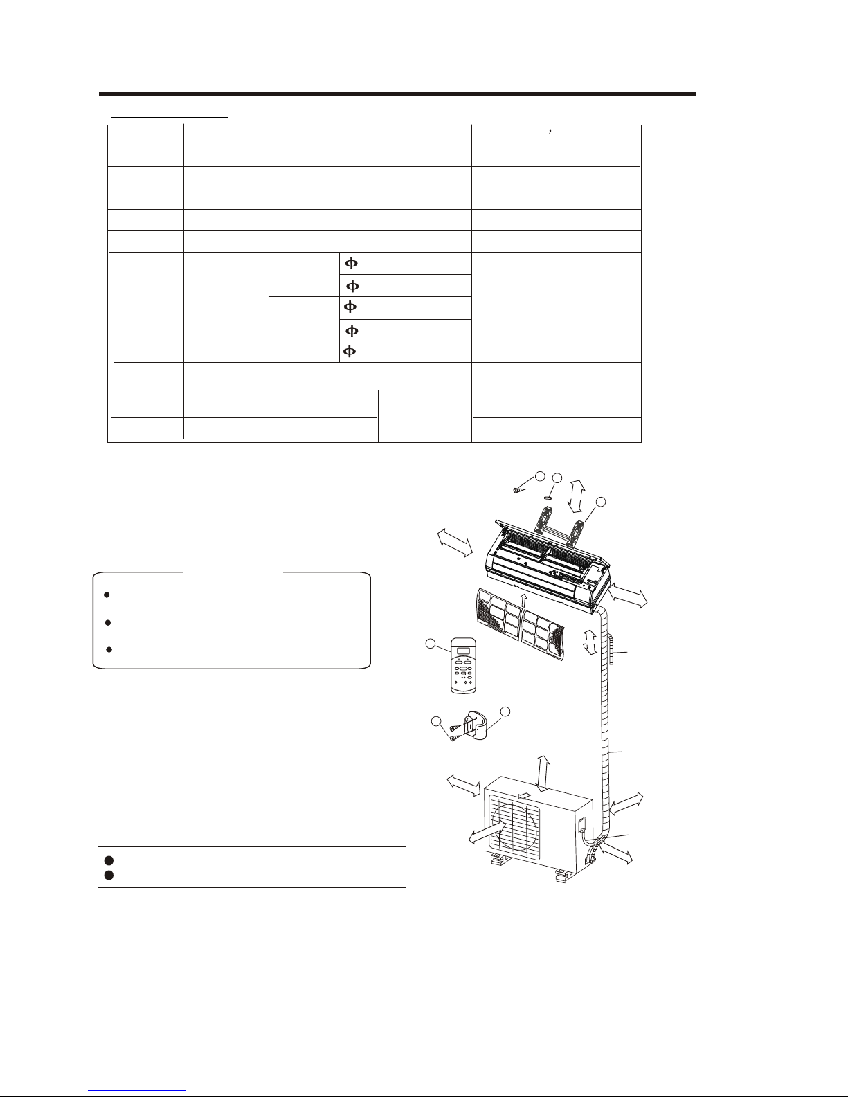
Note: Except the above parts provided, the other parts needed during installation you must
purchase.
This illustration is for explanation purposes only.
Copper lines must be insulated independently
Use a stud finder to locate studs to prevent
unnecessary damage to the wall.
A minimum pipe run of 3 metres is required
to minimise vibration & excessive noise.
Two of the A, B and C directions should be
free from obstructions.
CAUTION
.
Fig.3
8
9
7
>2.4m
12cm a
bove
12cm
above
15cm above
1
2
3
Loop the
connective
cable.
C
A
60cm above
6
0
c
m
ab
o
v
e
30cm
above
Air F
ilterAir F
ilter
Air Outlet
30cm
above
Wrapping tape
B
200cm
above
Additional drain pipe
Accessories
Parts you must purchase.
Consult the dealer about
the pipe size.
6.35
9.53
12.7
9.53
16
Self-tapping Screw B ST2.9X10
Remote controller
Installation Plate
Name of Accessories
Self-tapping Screw A ST3.9X25
Seal(For cooling & heating modles only)
Drain Joint(For cooling & heating modles only)
Connecting
pipe
Assembly
Liquid side
Clip Anchor
Number
Qty
Gas side
Remote controller holder
1
1
2
5-8(depending on models)
5-8(depending on models)
3
4
1
5
1
6
7
1
8
2
9
1
(C)
TEMP
AUTO
COOL
DRY
HEAT
FAN
HIGH
MED
LOW
MODE
FAN SPEED
TIMER ON
SLEEP
ON/OFF
TIMER OFF
AIR
DIRECTION
RESET LOCK
SET TEMPERATURE
SWING
LED
DISPLAY
TURBO
Optional
parts
6
INSTALLATION INSTRUCTIONS
Fig.4
Wall
Indoor
Outdoor
5-7mm
Fig.6
Fig.5
Indoor unit installation
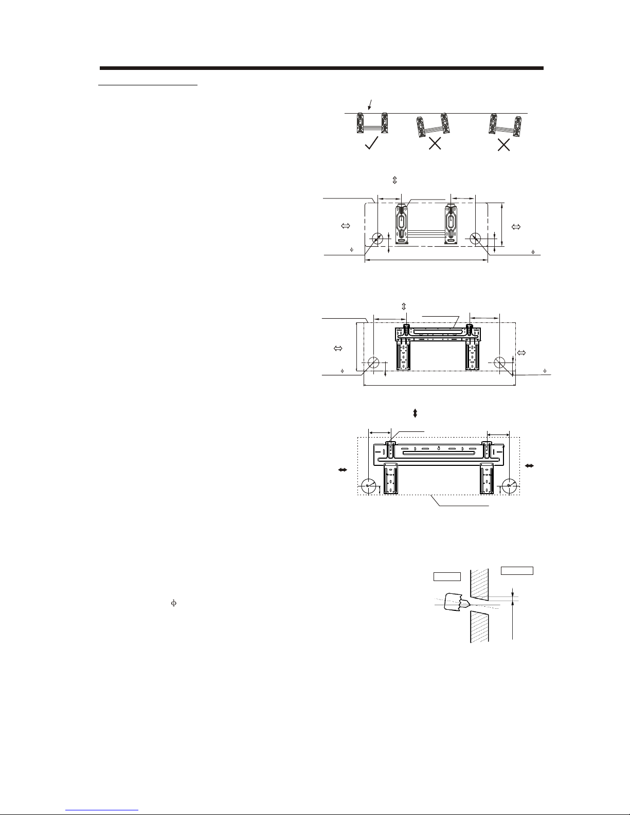
2. Drill a hole in the wall
Note:
1. Fit the Installation Plate
1. Fit the installation plate horizontally
on structural parts of the wall with
spaces around the installation plate.
2. If the wall is made of brick, concrete
or the like, drill eight (8) 5mm diameter
holes in the wall.Insert Clip anchor for
appropriate mounting screws.
3. Fit the installation plate on the wall
with eight (8) type “A” screws.
Fit the Installation Plate and drill
holes in the wall according to the
wall structure and corresponding
mounting points on the installation
plate. The installation plate provided
with the machine is differrent according
to the models.
(Dimensions are in “mm” unless
otherwise stated)
1. Determine hole positions according
to the diagramdetailed in Fig.5. Drill
one (1) hole ( 65mm) slanting slightly
to outdoor side.
2. Always use wall hole conduit when
drilling metal grid, metal plate or the like.
Correct orientation
of Installation Plate
Model C
Model D
150mm or more to ceiling
Indoor unit outline
Installation plate
292
Right rear side
refrigerant
pipe hole 65
Left rear side
refrigerant
pipe hole 65
120mm or
more to wall
120mm or
more to wall
920
45
185
150
45
A
45
B
Right rear side
refrigerant
pipe hole 65
Installation plate
Indoor unit outline
Left rear side
refrigerant
pipe hole 65
150mm or more to ceiling
120mm or
more to wall
120mm or
more to wall
Model A (A: 710, B: 250, C:100, D: 110)
Model B (A: 790, B:265, C:100, D: 150)
90
45
C
D
120mm or more
from the wall
120mm or more
from the wall
45
150mm or more from the ceiling
Indoor Unit Outline
Hooked Part
100
65
65
120
4
5
7
INSTALLATION INSTRUCTIONS
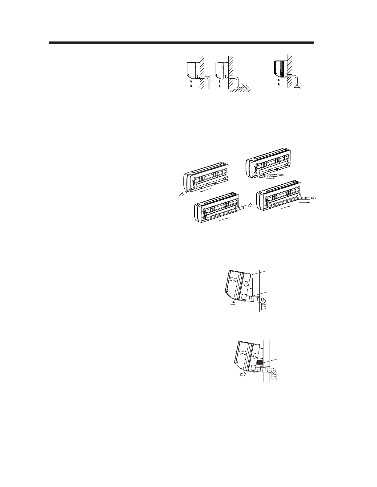
1. For the left-hand and right-hand piping,
remove the pipe cover from the side
panel.
2. For the rear-right-hand and rear-left-hand
piping, install the piping as shown.
3. Fix the end of the connective pipe. (Refer
to Tightening Connection in
REFRIGERANT PIPING CONNECTION)
Connective pipe installation
1. Pass the piping through the hole in the
wall.
2. Put the upper claw at the back of the
indoor unit on the upper hook of the
installation plate, move the indoor unit
from side to side to see that it is securely
hooked (see Fig.10 & Fig.11).
3. Piping can easily be made by lifting the
indoor unit with a cushioning material
between the indoor unit and the wall.
Get it out after finish piping.
4. Push the lower part of the indoor unit up
on the wall, then move the indoor unit
from side to side, up and down to check
if it is hooked securely.
4. Indoor unit installation
2. When connecting extension drain hose,
insulate the connecting part of extension
drain hose with a shield pipe, do not let
the drain hose slack.
Right-hand piping
Left-hand piping
Rear-right piping
Rear-left piping
Fig.8
Fig.9
Fig.11
Upper Hook
Lower Hook
Cushioning
material
Fig.10
Fig.7
Do not block water flow by a rise.
Do not put the end of
drain hose into water.
3. Connective Pipe and Drainage
Installation
1. Run the drain hose sloping downward.
Do not install the drain hose as
illustrated in Fig.7.
Drainage
8
INSTALLATION INSTRUCTIONS
5. Piping and wrapping
Bundle the tubing, connecting cable, and drain
hose with tape securely, evenly as shown in
Fig.12
Because the condensed water from rear of the
indoor unit is gathered in ponding box and is
piped out of room. Do not put anything else in
the box.
Indoor unit
Connective
pipe
Pipe room
Ponding box
Wrapping belt
Connective
cable
Drain hose
Fig.12
Connect the indoor unit first, then the
outdoor unit.
Do not allow the piping to let out from the
back of the indoor unit.
Be careful not to let the drain hose slack.
Heat insulated both of the auxiliary piping.
Be sure that the drain hose is located at
the lowest side of the bundle. Locating at
the upper side can cause drain pan to
overflow inside the unit.
Never intercross nor intertwist the power
wire with any other wiring.
Run the drain hose sloped downward to
drain out the condensed water smoothly.
CAUTION
Install the outdoor unit on a rigid base to
prevent increasing noise level and vibration.
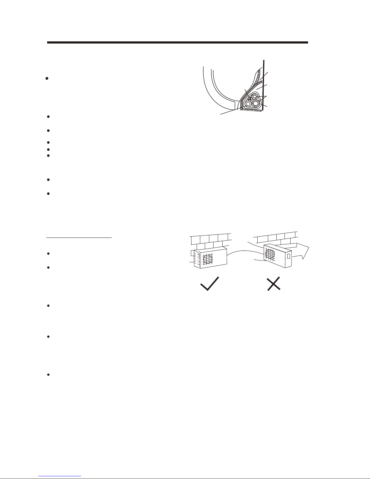
Determine the air outlet direction where the
discharged air is not blocked. In the case that
the installation place is exposed to strong wind
such as a seaside, make sure the fan operating
properly by putting the unit lengthwise along the
wall or using a dust or shield plates.
Specially in windy area, install the unit to prevent the admission of wind. If need suspending
installation, the installation bracket should
accord with technique requirement in the
installation bracket diagram.
The installation wall should be solid brick,
concrete or the same intensity construction, or
actions to reinforce, damping supporting should
be taken. The connection between bracket and
wall, bracket and the air conditioner should be
firm, stable and reliable.
Be sure there is no obstacle which block
radiating air.
Strong
wind
Fig.13
Outdoor unit installation
Outdoor installation precaution
 Loading...