

EMI CAHV09, CAHV18, CAHV12, CAHV24 Installation, Operation And Maintenance Manual
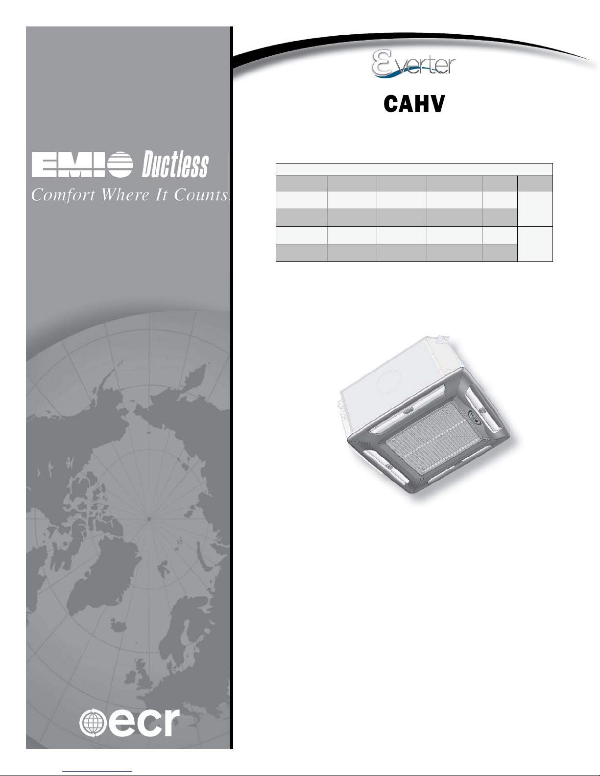
CAHV
V
p
s
Variable Speed Cassette Ductless
ariable S
Split System Air Handlers
Split System Air Handler
Straight Cool / Heat Pump Nominal Capacities
CAHV09 CAHV12 CAHV18 CAHV24 Units
eed Cassette Ductless
9,000 12,000 18,000 24,000 Btuh
2.6 3.5 5.3 7.0 kW
8400 8800 17000 19000 Btuh
2.5 2.6 5.0 5.6 kW
Installation, Operation and
Maintenance Manual
COOL
HEAT
An ISO 9001-2008 Certifi ed Company
ECRInternational,Inc.
2201 Dwyer Avenue,
Utica NY 13501
web site: www.ecrinternational.com
P/N# 240009099, Rev. C [08/08/2012]
TABLE OF CONTENTS
Receiving Information .................................................................................................................. 3
Important Safety Information ........................................................................................................ 4
General Product Information ......................................................................................................... 5
Dimensional/Physical Data ............................................................................................................ 6
Installation Considerations ............................................................................................................ 8
Mounting The Unit ....................................................................................................................... 9
Condensate Piping ......................................................................................................................12
Duct Connections .......................................................................................................................13
Refrigerant Piping .......................................................................................................................14
Refrigerant Processing .................................................................................................................15
Final Assembly ...........................................................................................................................17
Electrical Wiring .........................................................................................................................19
Optional Wired Wall Controller ......................................................................................................21
Optional (CAHV) Wired Wall Controller Operation ............................................................................22
Initial Start-Up — CAHV Units ......................................................................................................24
CAHV Controller Overview ...........................................................................................................28
Wired Wall Controller Confi guration ...............................................................................................31
Setting The Controller ................................................................................................................33
Hand Held Controller Operation ....................................................................................................35
Wired Wall Controller Operation ....................................................................................................39
CAHV Controller Features ............................................................................................................40
Maintenance ..............................................................................................................................42
Troubleshooting - General ............................................................................................................43
Troubleshooting - CAHV Units .......................................................................................................44
Frequently Asked Questions .........................................................................................................47
Specifi cations .............................................................................................................................48
System Performance ...................................................................................................................49
Test Unit Performance Data Sheet .................................................................................................50
Check our website frequently for updates: www.enviromaster.com
Information and specifi cations outlined in this manual in effect at the
time of printing of this manual. Manufacturer reserves the right to
discontinue, change specifi cations or system design at any time without
notice and without incurring any obligation, whatsoever.
2

RECEIVING INFORMATION
Shipping damage MUST be reported to the carrier IMMEDIATELY.
Examine exterior.
Remove cover and examine compressor and piping for signs of damage.
General Information
Installation shall be completed by qualifi ed agency. Retain
this manual and warranty for future reference.
Installer review this manual to verify unit has been installed
correctly. Run unit for one complete cycle to verify proper
function.
To obtain technical service or warranty assistance during or
after installation, contact your local representative.
Visit our web site www.enviromaster.com for local
representative listing.
For further assistance call 1-800-325-5479.
When calling for assistance, please have following
information ready:
Model Number_________________________
Serial Number_________________________
Date of installation______________________
3
IMPORTANT SAFETY INFORMATION
Become Familiar With Symbols
Identifying Potential Hazards.
!
All fi eld wiring shall conform to requirements of authority
having jurisdiction or in absence of such requirements:
• United States - National Electrical Code, ANSI/NFPA 70
• Canada - CSA C22.1 Canadian Electrical Code Part 1.
!
WARNING
Fire, explosion, and electrical shock hazard.
Improper assembly and/or installation could result
in death or serious injury. Read this manual and
understand all requirements before beginning
installation.
Become Familiar With Symbols
Identifying Potential Hazards.
!
DANGER
Indicates a hazardous situation which, if not
avoided, WILL result in death or serious injury.
Safety Information
• Installation by qualifi ed personnel.
• Turn off electrical supply before servicing unit.
• Inspect all parts for damage prior to installation and
start-up.
Do not use unit if it has damaged wiring, is not working
properly, or has been damaged or dropped.
• Connect to properly grounded electrical supply with
proper voltage as stated on rating plate.
• Have proper over-current protection (i.e. time-delay
fuse/HACR Breaker) as listed on Rating Plate.
• Connect unit to properly grounded electrical supply.
• Check rating plate on unit before installation. Verify
voltage shown is same as electric supply to unit. Rating
plate is located on top panel only.
• Tampering voids all warranties.
!
WARNING
Tampering with this unit is dangerous and could
result in serious injury or death. Do not modify or
change this unit.
!
WARNING
Indicates a hazardous situation which, if not
avoided, could result in death or serious injury.
!
CAUTION
Indicates a hazardous situation which, if not
avoided, could result in minor or moderate injury.
NOTICE
Indicates information which should be followed to
ensure proper installation and operation.
Product Description
• EMI Cassette Air handlers are available in two cabinet
sizes with four output capacities from 9,000–24,000
Btuh.
• Features include condensate pump with safety switch
and 36” (0.9 m) lift, measured from base or bottom
of unit, fresh air inlet, branch duct knockouts, and
motorized air vanes (models 18 and 24 only).
• Factory installed electric heat option. No fi eld installed
electric heat kits are available.
• Cassette air handler accepts optional wired wall control.
• Designed for low noise levels, easy installation, easy
maintenance and slim line fascia, insure minimum
intrusion into the conditioned environment.
• Cassette air handlers produce system SEER’s exceeding
13 when matched with EMI outdoor units:
Single-zone condensing units — S1CV/S1HV 09–24.
4

GENERAL PRODUCT INFORMATION
Standard Features
CAHV units
• Remote or optional wired wall control is required to
adjust settings and confi gure controller.
• When operated by optional wired wall control, controller
offers most functions. Hand held controller is required
for “Test” mode.
Materials of Construction
• Galvanized steel cabinet with fi re-resistant thermal and
acoustic foam insulation.
• Light grey high-impact ABS fascia.
• Expanded polystyrene drain pan with tough, fi re-
retardant thermoplastic liner.
Air Systems
• Fans are backward-curved impeller centrifugal design;
dynamically and statically balanced; and mounted on
integral mounting rails.
Single-fan models 9 - 24 are designed with fi re-
retardant plastic or aluminum impellers.
Multispeed motors are enclosed type with thermal
protection and sealed lifetime bearings.
• User accessible permanent, washable fi lter.
• Branch duct knockouts on three sides for remote
discharge locations; using no more than two nonadjacent sides.
• Fresh air intake capability on three sides of cabinet;
only two on models 9–12.
• Four plastic air vanes, motor driven with auto sweep or
fi xed position stop setting on models 18 - 24. Models
9–12 are equipped with manually-adjusted air vanes.
Coil
• Coil is seamless, copper tubing, arranged in staggered
confi guration, with enhanced aluminum fi ns, tested to
700 psig.
• Tubes are mechanically expanded for secure bonding to
fi n shoulder.
Refrigeration Circuit
Condensing units equipped with Electronic Expansion Valve
(EXV) and uses R410A refrigerant only.
System Options
Electric Heat Option
EMI heat option - heat pumps are intended to operate with
indoor air handler, with electric heat. If indoor air handler
without electric heat is matched with heat pump condenser
system delivers cold air during defrost.
Wired Wall Control Applications
Mechanical Characteristics
Condensate Pump
Air Vanes
Heating
Fresh Air Connection
Controls and Components - factory installed or
supplied
• Connections for optional wired wall control.
• Custom control board featuring programmability,
confi guration, and multiple modes of operation.
• Controls also feature anti-short-cycle timer, post purge
fan relay, and an on-board 30-amp electric heat relay.
• Condensate pump with 36” (0.9 m) lift (measured from
base of unit).
• 24V Transformer.
• Wired wall control.
• Electric Heat (@ 230V)
1.5 kW — models 9–12
3 kW — model 18 - 24
• CAHV units allow, optional wired wall control operation.
• Obtain wired control through EMI only.
• Metal framed fi lters are fi tted, reusable and may be
vacuum cleaned.
• Designed to carry water out of unit. Pump is fi xed to
mounting bracket which can be withdrawn from side of
chassis and incorporates inspection hole which allows
for visual check of pump during operation.
• Float switch stops cooling action, shuts off compressor
if pump becomes blocked or fails.
• Pump total lift is 36” (0.9 m) or less measured from
base or bottom of unit.
• Air outlet vanes are manually adjustable on models 9
and 12. Electrically motor driven on models 18 and 24.
• Motorized air vanes where fi tted can be set to auto
sweep or stopped in a fi xed position.
• Cassette may be fi tted with optional electric heaters
equipped with over-temperature limit switches. Consult
factory for available models with electric heat.
• Fresh air may be introduced to unit by addition of ducts
connected to fresh air knockouts on cassette case.
• Recommended maximum length is 10’ (3m) of
4” (0.1m) diameter duct. Fresh air volume is
approximately 7–10% of unit’s published maximum air
fl ow if more than 10% make up air is needed fresh air
booster fan is required.
• Refer to Performance Data section of this manual for
further information.
• Cassette is best installed in new construction or
existing construction with suspended or false ceiling
with enough clearance to accommodate concealing
piping and electrical connections to unit.
5
DIMENSIONAL/PHYSICAL DATA
Figure 1 - Dimensions: Models 9, 12, 18, & 24 (see Table 1, Page 7 )
Model 9-12
Model 18-24
Features
Optional discharge
knockouts
1
5¼-inch diameter
(3) available
Fresh air inlet
knockouts
1¼ x 2½ inches
2
- 9/12
(2) available
3x3 18/24
Condensate
discharge
3
½-inch diameter
Suction
4
connection
Liquid connection
5
Condensate pump
6
access panel
6
DIMENSIONAL/PHYSICAL DATA
Table 1 Dimensions — Models 9, 12, & 24 (see Figure 1, Page 6 )
Dimension
A
B
C
D
E
F
G
H
J (ref)
K
L
M
N (ref)
O
P (ref)
R (typical)
R1
R2
R3
S
T
U
V
W
X
Models 9 & 12 Model 18 & 24 Model 42
Inches mm Inches mm Inches mm
25.00 635 37.00 940 37.00 940
25.00 635 37.00 940 49.26 1251
22.50 572 32.44 824 32.44 824
2.04 52 2.00 51 2.04 52
22.57 573 30.40 772 44.68 1135
1.41 36 1.41 36 1.41 36
2.88 73 3.65 93 3.65 93
8.13 207 8.90 226 8.90 226
2.67 68 3.38 86 3.38 86
25.86 657 35.61 904 47.78 1214
12.76 324 18.69 475 24.73 628
1.73 44 1.97 50 1.97 50
2.16 55 2.72 69 2.72 69
5.12 130 5.12 130 5.12 130
11.34 288 12.05 306 14.01 356
1.50 38 1.63 41 1.63 41
19.50 495 29.19 741 29.19 741
23.27 591 31.20 792 42.66 1084
22.47 571 30.41 772 43.45 1104
7.19 183 6.87 174 6.87 174
3.73 95 2.58 66 4.98 126
4.88 124 5.50 140 5.47 139
3.50 89 4.93 125 5.00 127
2.50 64 3.97 101 4.00 102
4.69 119 4.37 111 4.37 111
7
INSTALLATION CONSIDERATIONS
Before Installing
• Determine best location for mounting unit for room air
circulation.
• Locate outdoor and indoor units as close together as
possible.
• Determine how power wires high and low-voltage,
condensate drainage, and refrigerant piping may be run
to and from unit.
• Insure interconnect tubing is within limits given in
Table 2 .
Table 2 - Tubing Specifi cations
S1CV
or
S1HV
Model
09
12 1/4” 1/2"
18 3/8” *5/8"
24 3/8" *5/8 “
*Bush to 5/8” @ Air Handler
Max.
Length
Equivalent
feet
100’
(30 m)
Max.
Lift
“H” “P” O.D. O.D.
35’
(11 m)
Max.
Trap
Height
20’
(6 m)
Liquid
Line
1/4” 1/2"
Suction
Line
Unpacking
Cassette fascia and main chassis are packaged together for
increased protection.
NOTICE
Do not throw template away with packaging.
1.
Remove banding straps and lift cardboard lid.
2.
Fascia is packed in bubble wrap on top of chassis.
Fascia is not attached to chassis for shipping.
3.
Cardboard template is between chassis and fascia.
4.
Lift fascia and template from box and set aside.
5.
Remove cassette chassis from box utilizing four corner
brackets for lifting.
6.
Do not use drain or refrigerant connections for lifting.
7.
In order to protect fascia from dirt and damage return
them to box until ready to install.
8.
Do not throw away two polystyrene blanking-off pieces
with packaging.
Piping may be roughed in before wallboard or panels are
placed in new construction. PVC pipe (3” or 4” I.D.) may
be used as pipe chase.
8

MOUNTING THE UNIT
Blanking off
Fascia discharge slot(s) need blanking off when ducts are
used to channel conditioned air to other areas.
• Position two polystyrene blanking off strips (provided)
in fascia discharge slots to direct air to ducts.
• Up to two non-adjacent sides may be blanked off.
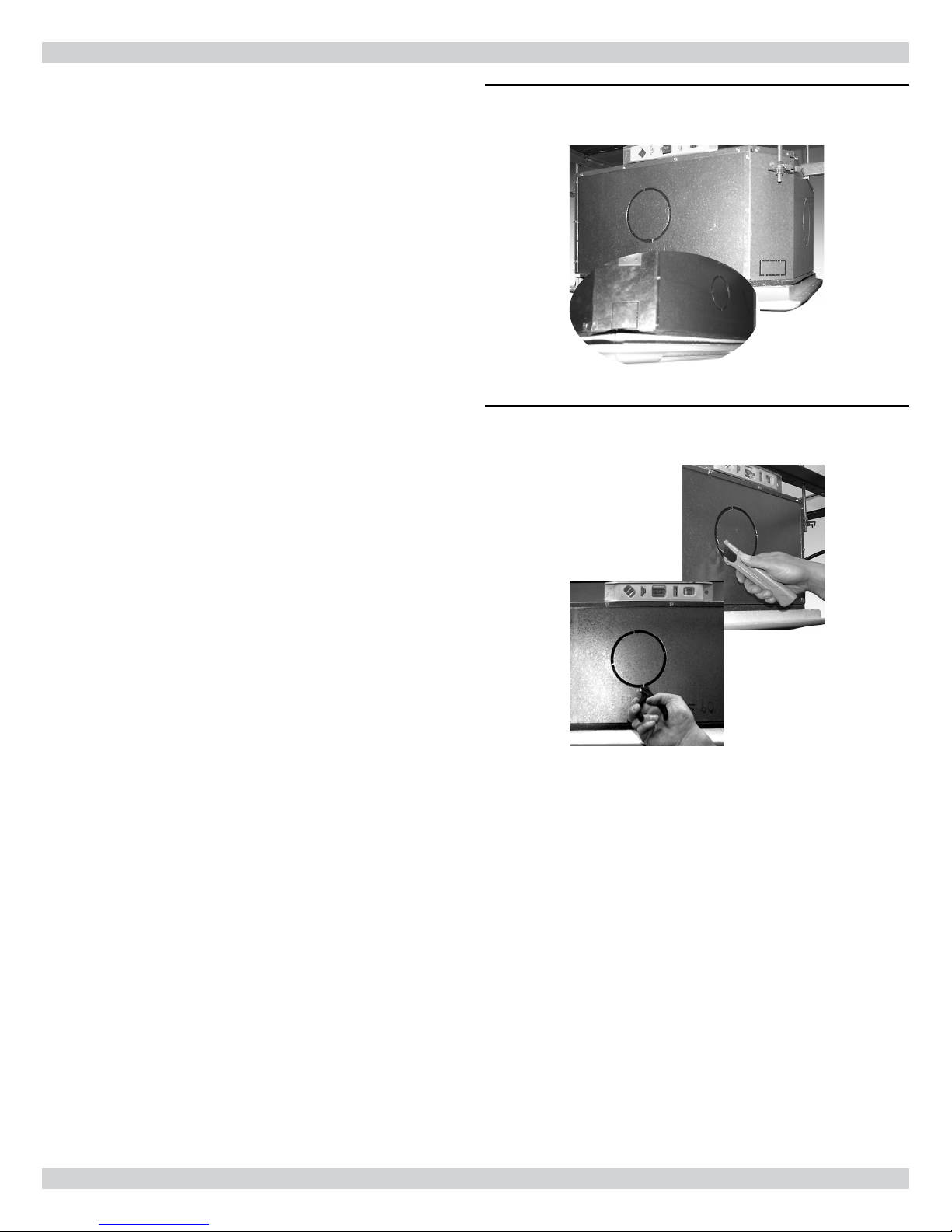
If fascia discharge slot needs blanking off —
1.
Remove inlet grilles and fi lters. See Figure 4 and
Figure 2, Page 9 .
2.
Turn fascia over to expose polystyrene insulation. See
Figure 3 .
3.
Push one polystyrene blanking-off pieces into recess in
polystyrene fascia insulation.
Figure 4 Models 9–12 — One Grille & One Filter
Figure 2 - Model 18 - 24 — Two Hinged Grilles
And Two Filters
Hinge
Figure 3 - Applying Blanking-Off Pieces
Blanking-Off
Pieces
9
MOUNTING THE UNIT
Positioning
Select cassette installation position.
1.
Pipe work, electrical connections, control box and
condensate pump access panels should be readily
accessible. Refer to cassette dimensions. See Figure 1,
Page 6 and Table 1, Page 7 .
2.
Position unit at least 5 ft. (1.5m) from wall or similar
obstruction.
3.
Position unit as close to center of room as possible to
insure even air distribution.
4.
Position unit so discharge air does not blow directly on
remote wall wired thermostat, if used.
5.
Do not position unit directly above any obstructions.
6.
Condensate drain should have suffi cient fall — 1” per
10’ (8 mm/m) in any horizontal run between cassette
and drain.
7.
Maximum condensate pump lift is 36” (0.9m) from
bottom of unit.
8.
Maintain minimum 1” (25.4mm) clearance above
cassette depth and false ceiling for proper installation.
Wired Wall Control Optional wired wall control contact
EMI for availability.
Locate optional wired wall mounted thermostat to insure
good temperature control. Select installation position.
1.
Position thermostat approximately 5 ft. (1.5m) above
fl oor level.
2.
Avoid external walls and drafts from windows and
doors.
3.
Avoid positioning near shelves and curtains as these
restrict air movement.
4.
Avoid heat sources (direct sunlight, heaters, dimmer
switches, etc.)
5.
Seal wiring holes in wall behind thermostat to avoid
drafts.
Ceiling Opening
NOTICE
Verify ceiling grid is supported separately from
the cassette. Do not support ceiling by any part of
cassette unit, fascia or any associated wiring or pipe
work.
Cut opening in false ceiling with size. See Table 4.
Table 4 - Ceiling Opening Sizes
Model Dimensions
9 & 12 23¼” x 23¼” (591 x 591 mm)
18 & 24 337/8” x 337/8” (860 x 860 mm)
Figure 5 - Spacing Requirements
Dimension A + 1” = Minimum Space Above False
Ceiling For Installation
A
+1”
A
Figure 6 - Ceiling Cutout/Rod Placement
Template (Shipped With Unit)
10
Rod
Positions
1.500 TYP
(51MM X 45°)
2.000 X 45° TYP
Model Dimension A
9 & 12 11.84” (0.3 m) min.
18 & 24 12.55” (0.32 m) min.
(38MM TYP)
Positions
Rod

MOUNTING THE UNIT
MAXIMUM
2”
(51mm)
Mounting Method
• In existing construction, remove enough ceiling panels
to provide clearance space for mounting unit to ceiling
joists.
• Before beginning installation, inspect unit location, test
strength of ceiling joists to insure they will support unit
weight.
• Determine mounting method:
A. Wooden beams use threaded rods, washers, and
nuts to suspend support brackets.
B. Metal structures, secure threaded rods on an
existing angle or install new support angle.
C. Newly built concrete slabs secure threaded rods
with inserts and embedded bolts.
D. For previously built concrete slabs install hanging
bolts with expansion anchor.
E. Follow local building codes for required safety
cables, braces, etc.
Mounting
1.
Use template to cut ceiling opening and determine rod
positions. See Figure 6, Page 10 .
2.
Install hanger bolts using 3/8” (10mm) all-thread rod
at centers. See Figure 6, Page 10.
Figure 7 - Mounting Brackets
Fold
bracket along
perforations
Table 5 - Ceiling Rod Positions
Model Dimension A Dimension B
9 & 12 19.50” (495mm) 22.87” (581mm)
18 & 24 29.19” (740mm) 30.80” (782mm)
3.
Prepare installation guides by folding metal bracket by
hand along perforations. See Figure 7 .
4.
Lift cassette onto hanging rods.
5.
Level at correct distance from ceiling with aid of
installation guides. See Figure 8 .
6.
Secure unit in position with locknuts and washers on
either side of cassette bracket.
7.
Insure threaded rod does not protrude more than 2”
(51mm) below mounting bracket. See Figure 9 .
If ceiling is not level or even, it is important to install
cassette level to insure correct pump operation and to
maintain fan clearances.
Place carpenter’s level on unit. Maximum slope of 1/8”
(3mm) over length of chassis toward condensate drain is
allowed. Slight discrepancy between cassette and ceiling
will be taken up by fascia foam seal.
Figure 8 - Positioning Installation Guides
CASSETTE
CASE
INNER CASE
INSULATION
Figure 9 -Threaded Rods Must Not Protrude
More Than 2 Inches Below Mounting
Brackets
11
2”
(51mm)
MAXIMUM
Correct
Incorrect
CONDENSATE PIPING
Cassette is supplied with 1/2” I.D. fl exible PVC hose for
connection to copper or plastic drain piping.
Cassette installation considerations
1.
Maximum pump lift is 36” (0.9m) from base or bottom
of unit.
2.
Highest point in condensate piping should be as close
to unit as possible. Prevents large volume of water
draining back into unit when it is switched off.
3.
Check valve at pump discharge to prevent water from
draining back into unit. Piping technique minimizes
issues should check valve become stuck open from
airborne debris.
4.
Slope condensate pipe-work downward from highest
point in direction of water fl ow with minimum gradient
of 1” per 10’ (8mm/1m). No uphill gradients other than
in fi rst 18” (0.45m) of pipe-work from cassette.
5.
When multiple cassettes are connected to common
condensate drain, insure drain is large enough to
handle total volume of condensate.
6.
Drain line vent may be required to prevent siphoning of
water from drain pan and associated noise.
Figure 10 - Highest Point Of Condensate Piping
Should Be As Close To Unit As Possible
Correct
Incorrect
Figure 11 - Condensate Drain
Condensate Drain Connection
12
Cassette 9-12
CASSETTE 18 -24
DUCT CONNECTIONS
Attach branch duct and fresh air duct collars to cassette
chassis using following steps.
Recommend install no more than 10 feet (3m) of branch
duct or fresh air duct.
1.
Locate knock-out holes. See Figure 12 .
Number of knockouts vary with unit size.
• Branch duct knock-outs are 5¼” (133mm) round.
• Fresh air knockouts are:
a. 1¼” x 2½” (32 x 64mm) rectangular models 9
& 12.
b. 3” (76mm) square models 18 & 24
3.
Cut black insulation around knock-out. See Figure 13 .
4.
Snip tabs holding knock-out in place.
5.
Remove metal knock-out and black insulation behind
it.
6.
Attach fi eld supplied duct collars to chassis using self-
drilling screws.
Figure 12 - Knockouts
Branch Duct Knockout
Cassette 9-12
CASSETTE 18 -24
Fresh Air
Knockout
Figure 13 - Cut Insulation And Snip Out
Knockouts
7.
Repeat above steps for remaining duct work.
13
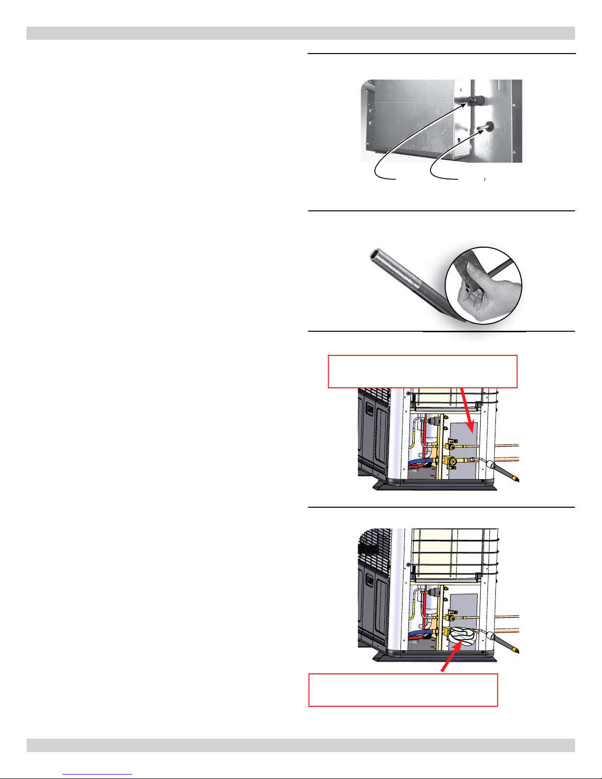
REFRIGERANT PIPING
Add heat shield behind valve when brazing to
prevent damage to unit.
Add wet rag over valve to keep from
melting internal valve components.
Piping Preparation
• Avoid piping on wet and rainy days.
• Use only clean, refrigeration-grade copper tubing.
• Use tubing benders to guard against kinking.
• Verify no burrs remain on fi ttings.
• Cap ends of lines until ready for connections. Verify
plastic end caps remain in place when inserting through
wall openings.
• Insulate both lines.
• Isolate tubing from transmitting vibration to building or
unit and avoid contact with sharp edges.
• Wrap refrigeration valves with wet rag “heat sink” to
protect valves while brazing. See Figure 31, Page 20 .
Refrigerant Piping
1.
Clean tubing ends. Insert into fi ttings. See Figure 15 .
2.
Protect valves by wrapping with wet rag “heat sink”
before brazing. See Figure 16 .
3.
Use shield to protect paint. Shield may be made from
scrap metal. See Figure 14.
4.
Braze tubing into fi ttings.
Figure 14 - Piping Connections At Unit
(When a reducing bushing is required, install
only at the indoor suction-line connection.)
Suction Line Liquid Line
Figure 15 - Clean Ends Of Tubing
Figure 16 - Wet Rag “Heat Shield Over Valves
Add heat shield behind valve when brazing to
prevent damage to unit.
5.
Install all panels removed to this point. Panels are
required for proper air fl ow.
Figure 17 - Make Shield To Protect Paint
Add wet rag over valve to keep from
melting internal valve components.
14
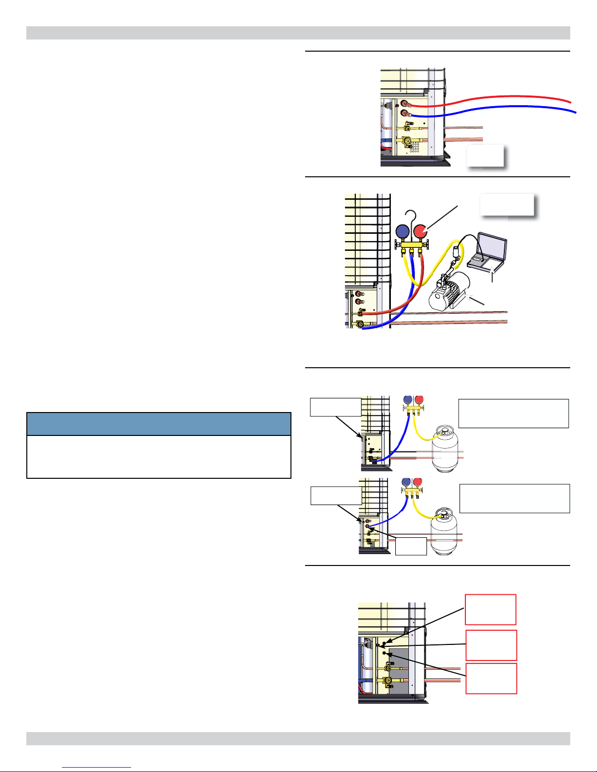
REFRIGERANT PROCESSING
A
B
C
S1HV
Shown
B
C
Charging Unit
1.
Attach manifold set, vacuum pump, & micron Gauge.
See Figure 18 .
2.
Evacuate line to 500 microns or less to insure all
moisture has been removed and there are no leaks.
See Figure 19 .
• Evacuate
• Pressurize with 100psi
N2 or Nitrogen
• Evacuate again
• Charge with R410A
3.
Verify evacuation and leak free joints. Back-seat valves
(counter-clockwise) to open and allow factory charge to
fi ll lines and indoor unit. See Figure 20 .
Refer to refrigerant charge table for specifi ed charge.
4.
Charge to proper weight. Charge based on feet of
interconnect. Only add/remove R410A in liquid
form. See Table 6, Page 16 .
5.
Refer to charts beginning on page 16 to “fi ne tune” the
refrigerant charge to meet your conditions.
Systems require fi eld charge adjustments. Refer to
“Refrigerant Charge Tables” for proper weight charge
and Operation Charts for proper system pressures and
temperatures at different outdoor conditions. Sub-cool
should be used for fi nal system charge.
Charging should be suitable charge weighed in with
scale.
NOTICE
Figure 18 - Manifold Set Connections At Unit
HIGH PRESSURE
RED
LOW PRESSURE
BLUE
S1HV
Shown
Figure 19 - Manifold Set Up For Evacuation
S1HV
Shown
C
B
A
Manifold
C
Micron Gage
A
B
Vacuum Pump
Figure 20 - Charging
High Pressure
Switch
Straight Cool Condenser Use
Valves
It is illegal to discharge refrigerant into the
atmosphere. Use proper reclaiming methods &
equipment when installing or servicing this unit.
• Measure all heat pump saturated suction pressures at
the Common Suction Port not vapor Service Valve.
• Common Suction Port includes pressure drop and
temperature increase through reversing valve resulting
in a more accurate and complete system charge.
• Port may also be used to charge system in heating
mode when both sides of line set are at high system
pressures or to determine saturated evaporator
pressure while in heating mode.
High Pressure
Switch
Common
Suction
Heat Pump Unit Use Common
Suction
Figure 21 - Common Suction, Discharge, and
High Pressure Switch
COMMON
DISCHARGE
HIGH
PRESSURE
SWITCH
COMMON
SUCTION
PORT
15

REFRIGERANT PROCESSING
Use following example to fi nd charge adjustment and
system charge for any air handles and tubing length.
Line Adjustment = (Line Charge/FT) x Line Length
System Total = Factory Charge + Line Adjustment
Round to nearest ounce and allow for gauges and hoses.
Table 6 - S1CV / S1HV R410A Refrigerant
Charge Table
Condenser Cassette
Pairing
S1CV9000 CAHV09 .25 oz./ft (23 g/m) 39.5oz (1120g)
S1CV2000 CAHV12 .25 oz./ft (23 g/m) 39.5oz (1120g)
S1CV8000 CAHV18 .64 oz./ft 59 g/m) 54.0oz (1531g)
S1CV4000 CAHV24 .64 oz./ft (59 g/m) 54.0oz (1531g)
S1HV9000 CAHV
S1HV2000 CAHV
S1HV8000 CAHV
S1HV4000 CAHV
09
12
18
24
Line Charge
Per Foot
.25 oz./ft (23 g/m) 39.5oz (1120g)
.25 oz./ft (23 g/m) 39.5oz (1120g)
.64 oz./ft (59 g/m) 54.0oz (1531g)
.64 oz./ft 59 g/m) 54.0oz (1531g)
Factory
Charge
16
 Loading...