

EMI CAHG09, CAHH12, CAHH24, CAHH09, CAHG12 Installation, Operation And Maintenance Manual
...
P/N 240008108, Rev. B [082509]
CACG/CAHG &
CACH/CAHH
High-Efciency Cassette Ductless Split System Air Handlers
Straight cool / Heat pump nominal capacities
CAHG09
CAHH09
CAHG12
CAHH12
CAHG24
CAHH24
Units
9,000 12,000 18,000 24,000 Btuh
2.6 3.5 5.3 7. 0 kW
Straight cooling only — circuit load — two circuits
CACG-36 & CACH-36
Units
30,000 36,000 Btuh
8.8 10.5 kW
Installation, Operation and
Maintenance Manual
ECR International LLC
2201 Dwyer Ave.
Utica, NY 13504
www.enviromaster.com
An ISO 9001-2000 Certified Company
CAHH12

CACG/CAHG & CACH/CAHH
Air Handlers
• Installation, Operation and Maintenance Manual •
Comfort where it counts 2 P/N 240008108, Rev. B [082509]
Contents
To the Installer
Retain this manual and warranty for
future reference. Before leaving the premises, review this manual to be sure the unit
has been installed correctly and run the
unit for one complete cycle to make sure
it functions properly.
To obtain technical service or warranty
assistance during or aer the installation
of this unit, contact your local representative. For a local representative listing, visit
our web site:
www.enviromaster.com
For further assistance call:
1-800-228-9364
When calling for assistance, please have
the following information ready:
Model Number _____________
Serial Number _____________
Date of installation ___________
WARNING
Shipping damage MUST
be reported to the carrier
IMMEDIATELY.
Examine the exterior. Remove
cover and examine compressor
and piping for signs of damage.
NOTICE
e EMI Ductless Series of high eciency evaporators are backed by EMI
and ECR International and are tested,
rated, and certied in accordance with
AHRI Standard 210/240-2008 and
UL-1995.
Due to ongoing product development,
product designs and specications may
change without notice.
Please contact the factory for more
information.
Contents . . . . . . . . . . . . . . . . . . . . . . . . . 2
Read Before Proceeding
. . . . . . . . . . . . . . . 3
Verify Unit Before Installing (continued)
. . . . . 6
Piston/Orifice Replacement (when required)
. . 7
Mounting the Unit
. . . . . . . . . . . . . . . . . . . 8
Condensate Piping
. . . . . . . . . . . . . . . . . . .13
Duct Connections
. . . . . . . . . . . . . . . . . . .14
Refrigerant Piping
. . . . . . . . . . . . . . . . . . .15
Refrigerant Processing
. . . . . . . . . . . . . . . .18
Final Assembly
. . . . . . . . . . . . . . . . . . . . .19
Final Assembly (continued)
. . . . . . . . . . . . .20
Remote Thermostat Selection (optional for CACH/
CAHH)
. . . . . . . . . . . . . . . . . . . . . . . . . . .21
Electrical Wiring
. . . . . . . . . . . . . . . . . . . . .22
Initial Start-Up — CACG/CAHG Units ONLY
. . .24
Initial Start-Up — CACH/CAHH Units ONLY
. . .28
CACH/CAHH Microprocessor Controller Overview
31
Setting the CACH/CAHH Controller . . . . . . . .35
CACH/CAHH Microprocessor Controller
Operation
. . . . . . . . . . . . . . . . . . . . . . . .38
CACH/CAHH Remote Thermostat Operation
. .45
CACH/CAHH Controller Features
. . . . . . . . . .47
CACH/CAHH Controller Fault Conditions
. . . . .48
Maintenance
. . . . . . . . . . . . . . . . . . . . . . .49
Troubleshooting — General
. . . . . . . . . . . . .50
Troubleshooting — CACG/CAHG Units
. . . . . .52
Troubleshooting — CACH/CAHH Units
. . . . . .55
Frequently Asked Questions
. . . . . . . . . . . . .56
Dimensions
. . . . . . . . . . . . . . . . . . . . . . .58
Dimensions (continued)
. . . . . . . . . . . . . . .59
Specifications
. . . . . . . . . . . . . . . . . . . . . .60
System Options
. . . . . . . . . . . . . . . . . . . . .61
Test Unit Performance Data Sheet
. . . . . . . . .63
EMI’s Product Line
. . . . . . . . . . . . . . . . . . .64
CACG/CAHG & CACH/CAHH
Air Handlers
• Installation, Operation and Maintenance Manual •
P/N 240008108, Rev. B [082509] 3
Read Before Proceeding
Recognize this symbol as an indication of
important safety information.
WARNING
Completely read all instructions
prior to assembling, installing, operating, or repairing this product.
Inspect all parts for damage prior to
installation and start-up. e EMI Ductless high eciency evaporator must be
installed ONLY by qualied installation
personnel.
DANGER
Tampering with this unit is danger-
ous
. Tampering voids all warranties.
DO NOT aempt to modify or change
this unit in any way.
DANGER
e EMI ductless unit must:
Be connected to a properly grounded •
electrical supply with the proper
voltage as stated on the rating plate.
Have proper overcurrent protection •
(time-delay fuse/HACR Breaker) as
listed on the rating plate.
Ensure there are no power feeds to the
unit such as fire alarm circuits, BMS
circuits, etc.
Failure to follow these instructions can
result in a re, explosion, or electrical
shock causing property damage, personal
injury, or death.
Safety Instructions
is manual is intended as an aid to qualied service personnel for proper installation, operation, and maintenance of the
EMI Ductless high eciency evaporator.
Read these instructions thoroughly and
carefully before aempting installation or
operation.
Failure to follow these instructions may
result in improper installation, operation,
service, or maintenance, possibly resulting
in re, electrical shock, property damage,
personal injury, or death.
Read all instructions before using this
unit. Install or locate this unit only in accordance with these instructions. Use this
unit only for its intended use as described
in this manual.
Check the rating plate on the unit before
installation to make certain the voltage
shown is the same as the electric supply to
the unit. e rating plate is located on the
top panel only.
This unit must be connected only to a
properly grounded electrical supply. Do
not fail to properly ground this unit.
Turn o the electrical supply before servicing the unit.
Do not use the unit if it has damaged wiring, is not working properly, or has been
damaged or dropped.

CACG/CAHG & CACH/CAHH
Air Handlers
• Installation, Operation and Maintenance Manual •
Comfort where it counts 4 P/N 240008108, Rev. B [082509]
Product description
e EMI Ductless Cassee Air handlers •
are available in three cabinet sizes with
four output capacities from 9,000–24,000
Btuh, and two cooling only capacities
from 30,000–36,000 Btuh.
Key features include a condensate pump •
with safety switch and a 36” (0.9 m) li
(measured from the base or boom of
the unit), fresh air inlet and branch duct
knockouts, and motorized air vanes models 24 and 36 only).
Electric heat is a factory-installed option •
ONLY (there are no eld installed electric
heat kits available). (See NOTICE on
next page.)
The cassette air handler accepts a 24 •
volt thermostat control (thermostat not
included).
Designed for low noise levels, easy instal-•
lation and maintenance and a slim line
fascia, all ensure minimum intrusion into
the conditioned environment.
Due to ongoing product development, all •
designs and specications are subject to
change without notice.
These cassette air handlers produce •
system SEER’s meeting or exceeding 13
when matched with EMI outdoor units:
Single-zone condensing units –
S1CG/S1HG 09–24 and S1CG 30–
36.
Dual-zone condensing units –
S2CG/S2HG side discharge.
Multi-zone, top discharge condens- –
ing units T2CG/T2HG, T3CG/
T3HG, or T4CG/T4HG.
Refer to specications contained in –
this document.
All EMI air handlers are backed by En-•
viromaster International LLC and are
tested, rated, and certied in accordance
with ARI standards 210/240-2008 and
UL 1995.
Verify Unit Before Installing
Standard features
CACG/CAHG units
“G” units require a remote thermostat •
for operation. They do not include an
onboard controller.
External thermostat required.•
CACH/CAHH units
“H” units include an on-board micropro-•
cessor controller with infrared remote.
e remote is required to adjust seings •
and congure the controller.
Also included is a bank of DIP switches for •
seing operating behavior. ese can be
used to select operation by the on-board
controller or by a remote thermostat.
When operated by remote thermostat, the •
controller oers limited options.
Materials of Construction
Galvanized steel cabinet with re-resistant •
thermal and acoustic foam insulation.
Light grey high-impact ABS fascia.•
Expanded polystyrene drain pan with a •
tough, re-retardant thermoplastic liner.
Air Systems
Fans are backward-curved impeller •
centrifugal design; dynamically and statically balanced; and mounted on integral
mounting rails.
Single-fan models 9, 12 & 24 are –
designed with re-retardant plastic
or aluminum impellers.
Twin-fan model 36 is designed with –
re-retardant plastic impellers.
Motors are multispeed, enclosed type –
with thermal protection and sealed
lifetime bearings.
Permanent, washable lter (user acces-•
sible).
Branch duct knockouts on three sides •
for remote discharge locations (using no
more than two non-adjacent sides).
Fresh air intake capability on three sides of •
cabinet (only two on models 9–12).

CACG/CAHG & CACH/CAHH
Air Handlers
• Installation, Operation and Maintenance Manual •
P/N 240008108, Rev. B [082509] 5
Verify Unit Before Installing (continued)
Four plastic air vanes, motor driven with •
auto sweep or xed position stop seing
on models 24 and 36. Models 9–12 are
equipped with manually-adjusted air
vanes.
Coil
Coil is seamless, copper tubing, arranged •
in staggered conguration, with enhanced
aluminum ns, tested to 600 psig.
e tubes are mechanically expanded for •
secure bonding to n shoulder.
Refrigeration Circuit
Units are equipped with a serviceable •
fixed orifice expansion device and use
R410A refrigerant only.
Controls and Components
(factory installed or supplied)
Connections for 24V remote thermo-•
stat.
Custom control board featuring program-•
mability, configuration, and multiple
modes of operation. (CACH/CAHH
only)
Controls also feature anti-short-cycle •
timer, post purge fan relay, and an onboard 30-amp electric heat relay.
Condensate pump with 36” (0.9 m) li •
(measured from base of unit).
24V Transformer.•
System options
24V remote thermostat.•
Electric Heat (@ 230V) •
1.5 kW models 9–12 –
3 kW model 24 –
5 kW model 36. –
Heat pump applications
NOTICE
Electric heat option EMI heat pumps
are intended to operate with an indoor
air handler, with electric heat. If an indoor air handler without electric heat is
matched with a heat pump condenser,
the system will deliver cold air during
defrost.

CACG/CAHG & CACH/CAHH
Air Handlers
• Installation, Operation and Maintenance Manual •
Comfort where it counts 6 P/N 240008108, Rev. B [082509]
Remote thermostat applications
CACG/CAHG units require a remote •
thermostat for operation. CACH/
CAHH units can be operated by a remote
thermostat by conguring the unit’s DIP
switches.
A thermostat can be obtained through •
EMI or your local distributor.
NOTICE
Make sure the thermostat is suitable for
unit operation (i.e., cooling only, cooling/electric heat, heat pump.) See thermostat requirements in this manual.
Mechanical characteristics
Filters
Metal framed lters are ed. ese are •
reusable and may be vacuum cleaned.
Condensate pump
A condensate pump is designed to carry •
water out of the unit. e pump is xed
to a mounting bracket which can be
withdrawn from the side of the chassis
and incorporates an inspection hole to
allow a visual check of the pump during
operation. A oat switch stops the cooling action (shuts off the compressor)
should the pump become blocked or fail.
(Important: Total li for this pump is 36”
(0.9 m) or less.)
Air vanes
Air outlet vanes are manually adjustable •
on the models 9 and 12 or driven by an
electric motor on the models 24 and 36.
Where ed, the motorized air vanes can •
be set to auto sweep or can be stopped in
a xed position.
Heating
e cassee may be ed with electric •
heaters which are equipped with overtemperature limit switches. Consult
factory for available models with electric
heat.
Fresh air connection
Fresh air may be introduced to the unit •
by the addition of ducts connected to the
fresh air knockouts on the cassee case.
Recommended maximum length is 10’ •
(3m) of 4” (0.1m) diameter duct. e
fresh air volume is approximately 7–10%
of the unit’s published maximum air ow
(if more than 10% make up air is needed,
a fresh air booster fan is required).
Refer to Performance Data section of this •
manual for further information.
e cassee is best installed in new con-•
struction or existing construction with a
suspended or false ceiling with enough
clearance to accommodate concealing
the piping and electrical connections to
the unit.
Verify Unit Before Installing (continued)

CACG/CAHG & CACH/CAHH
Air Handlers
• Installation, Operation and Maintenance Manual •
P/N 240008108, Rev. B [082509] 7
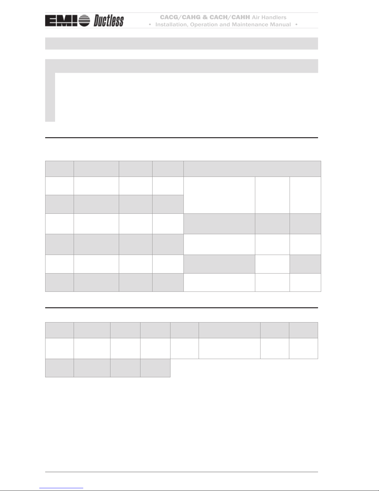
Piston/Orifice Replacement (when required)
NOTICE — model 24 with T2, T3 or T4 condenser
Piston/orifice replacement e factory-installed piston/orice must be replaced
when a model 24 air handler is matched with a T2CG/T2HG4400, T2CG/T2HG2400
or T2C/T3CG/T3H2240 condenser that has a 24,000 Btuh compressor (designated
by a “4” in the capacity decoding eld). e piston will need replacement only on the
24,000 Btuh zone.
All other applications use the factory-installed orice.
Follow these instructions to replace the orice BEFORE mounting the unit.
Replacing the piston/orifice
Disassemble the orice joint, remove the 1.
factory-installed orice, and replace with
the orice listed in Figure 1 (supplied in
the Kit Bag).
Piston/orifice replacementFigure 1
Model Condenser Factory-installed orifice size
(Inches)
Replacement orifice size
(Inches)
CAHG/
CAHH
24
T2C/T2H4400
T2C/T2H2400
T3C/T3H2240
0.054 0.047
CACG/
CACH
36
S1CG3000
.070 .063
Make sure the o-ring is in good condition 2.
and properly installed.
18 Piston Change

CACG/CAHG & CACH/CAHH
Air Handlers
• Installation, Operation and Maintenance Manual •
Comfort where it counts 8 P/N 240008108, Rev. B [082509]
Mounting the Unit
Before installing, consider:
Determine the best location for mounting •
the unit for room air circulation.
Locate outdoor and indoor units as close •
together as possible.
Determine how power wire (high and •
low-voltage) condensate drainage, and
refrigerant piping may be run to and from
the unit.
Ensure that interconnect tubing is within •
the limits given in Table 1.
Tubing specificationsTable 1
S1CG
or
S2CG
Model
Max.
Length
Equivalent
feet
Max.
Lift
Max.
Trap
Height
Liquid
Line
Suction
Line
“H” “P” O.D. O.D.
09
50’
(15 m)
20’
(6 m)
15’
(5 m)
1/4" 1/2"
12 1/4" 1/2"
18
100’
(30 m)
35’
(11 m)
20’
(6 m)
3/8" 5/8"
24 3/8" 3/4"
30 3/8" 3/4"
36 3/8" 3/4"
NOTICE
Piping may be roughed in before wallboard or panels are placed in new construction. PVC pipe (3” or 4” I.D.) may
be used as a pipe chase.
Unpacking
e Cassee fascia and main chassis are packaged together for increased protection.
Remove the banding straps and li the 1.
cardboard lid.
Fascia is packed in bubble wrap and on 2.
top of the chassis (fascia is not aached
to the chassis for shipping).
Cardboard template is between the chas-3.
sis and the fascia.
NOTICE
Do not throw template away with packaging
Li the fascia and template from the box
4.
and set aside.
Remove the cassette chassis from the
5.
box utilizing the four corner brackets
for liing.
WARNING
Do not use the drain or refrigerant connections for liing.
In order to protect the fascia from dirt and 6.
damage, it should be returned to the box
until it is ready to be installed.
NOTICE
Do not throw away the two polystyrene
blanking-o pieces with packaging

CACG/CAHG & CACH/CAHH
Air Handlers
• Installation, Operation and Maintenance Manual •
P/N 240008108, Rev. B [082509] 9
Mounting the Unit (continued)
Blanking off
e fascia discharge slot(s) will need blanking o when ducts are used to channel the
conditioned air to other areas.
Position the two polystyrene blanking o •
strips (provided) in the fascia discharge
slots to direct the air to the ducts.
Up to two non-adjacent sides may be •
blanked o.
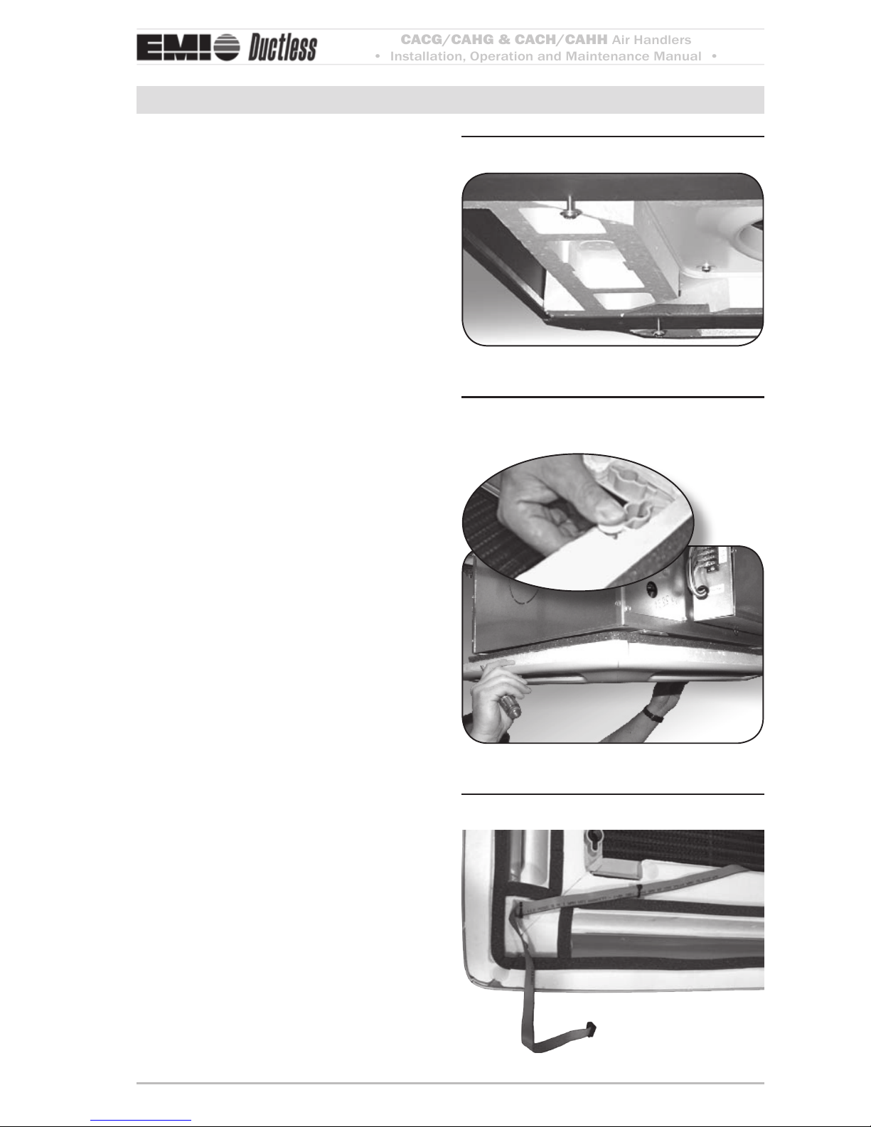
If the fascia discharge slot needs
blanking off —
Remove the inlet grilles and lters (see 1.
Figure 2, Page 9) and (Figure 3, Page 9).
Once the grilles and lters are removed, 2.
turn the fascia over so the polystyrene
insulation is exposed (Figure 4, Page 9).
Push one of the polystyrene blanking-o 3.
pieces into the recess in the polystyrene
fascia insulation.
Models 9–12 — one grille & one Figure 2
filter
Model 24 — two hinged grilles Figure 3
and two filters (Model 36, not
shown has three grilles and
three filters)
hinge
Applying blanking-off piecesFigure 4
blanking-off
Pieces
CACG/CAHG & CACH/CAHH
Air Handlers
• Installation, Operation and Maintenance Manual •
Comfort where it counts 10 P/N 240008108, Rev. B [082509]
Mounting the Unit (continued)
Positioning
e cassee installation position should be
selected with the following in mind:
Pipe work, electrical connections, control 1.
box and condensate pump access panels
should be readily accessible. Refer to the
cassee dimensions in the back of this
manual.
e unit should be positioned at least 5 2.
. (1.5m) from a wall or similar obstruction.
Position the unit as close to the center 3.
of the room as possible to ensure air is
distributed evenly.
Position the unit so that the discharge 4.
air does not blow directly on the remote
thermostat, if used.
e unit should not be positioned directly 5.
above any obstructions.
e condensate drain should have suf-6.
cient fall 1” per 10’ (8 mm/m) in
any horizontal run between cassee and
drain.
Maximum condensate pump li is 36” 7.
(0.9m).
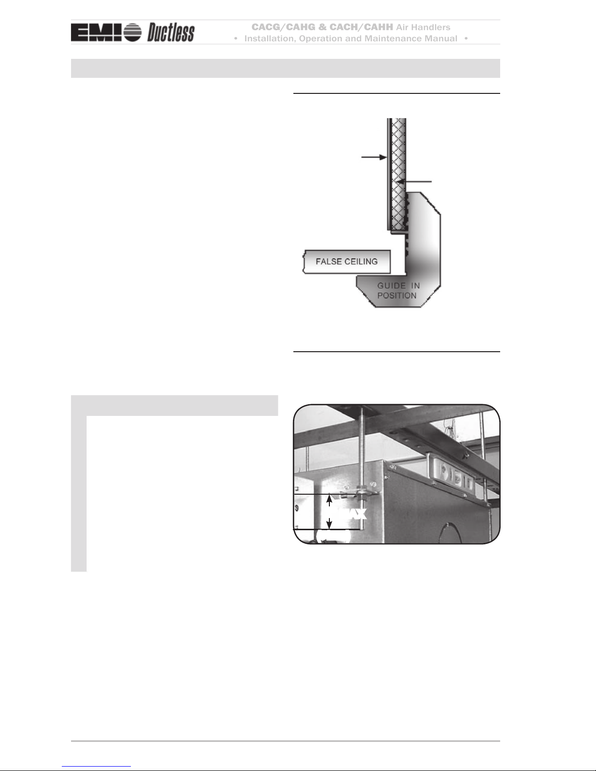
ere should be a minimum 1” (25.4mm) 8.
clearance above the depth of the cassee
and the false ceiling for proper installation. See (Figure 5, Page 10). (See the
cassee dimensions in the back of this
manual for cabinet sizing).
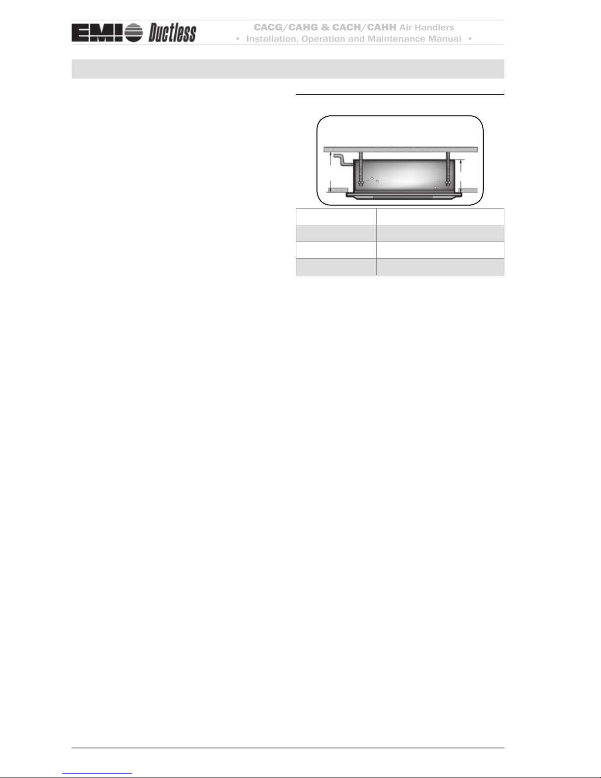
Spacing requirementsFigure 5
Dimension A + 1” = minimum space
above the false ceiling for installation
A
A +1”
Model Dimension A
9 & 12 11.84” (0.3 m) min.
24 12.55” (0.32 m) min.
36 14.51” (0.37 m) min.
Remote thermostat
A remote thermostat can be obtained through
EMI or your local distributor. e remote
thermostat is required for CACG/CAHG
units, optional for CACH/CAHH units.
In addition to positioning the cassee correctly, it is very important to locate the wall
mounted thermostat in the optimum position
to ensure good temperature control. The
installation should be selected with the following points in mind:
Position the thermostat approximately 5
1.
. (1.5m) above oor level.
Avoid external walls and dras from win-
2.
dows and doors.
Avoid positioning near shelves and cur-
3.
tains as these restrict air movement.
Avoid heat sources (direct sunlight, heat-
4.
ers, dimmer switches, etc.)
Seal wiring holes in the wall behind the
5.
thermostat to avoid dras.
CACG/CAHG & CACH/CAHH
Air Handlers
• Installation, Operation and Maintenance Manual •
P/N 240008108, Rev. B [082509] 11
Mounting the Unit (continued)
Mounting method
In existing construction, remove enough •
ceiling panels to provide clearance space
for mounting unit to ceiling joists.
Before beginning the installation, inspect •
the unit location, test the strength of the
ceiling joists to insure they will support
the weight of the unit.
Determine mounting method: •
On wooden beams use threaded rods, –
washers, and nuts to suspend support
brackets.
With metal structures, secure thread- –
ed rods on an existing angle or install
a new support angle.
On newly built concrete slabs secure –
threaded rods with inserts and embedded bolts.
For previously built concrete slabs –
install hanging bolts with an expansion anchor.
Follow local building codes for required •
safety cables, braces, etc.
Ceiling opening
NOTICE
Make sure the ceiling grid is supported
separately from the Cassee. e ceiling
must not be supported by any part of the
Cassee unit, fascia or any associated
wiring or pipe work.
Cut an opening in the false ceiling with the
size shown in (Table 2, Page 11).
Ceiling opening sizesTable 2
Model Dimensions
9 & 12 23¼” x 23¼” (591 x 591 mm)
24 33/” x 33/” (860 x 860 mm)
36 46” x 33/” (1168 x 860 mm)
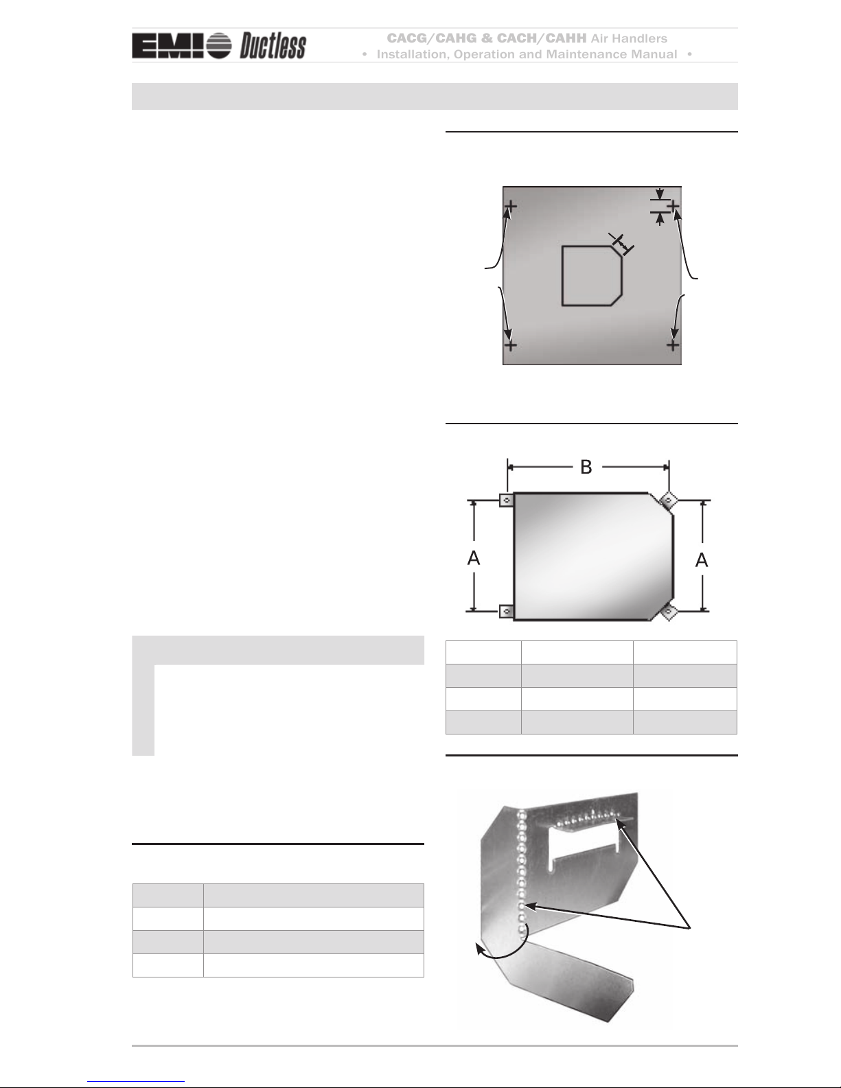
Ceiling cutout/rod placement Figure 6
template (shipped with unit)
(51mm x 45°)
2.000 x 45° TYP
rod
Positions
1.500 TYP
rod
Positions
(38mm TYP)
Ceiling rod positionsTable 3
A
A
B
Model Dimension A Dimension B
9 & 12 19.50” (495mm) 22.87” (581mm)
24 29.19” (740mm) 30.80” (782mm)
36 29.19” (740mm) 43.06” (1094mm)
Mounting bracketsFigure 7
Fold
bracket along
perforations
CACG/CAHG & CACH/CAHH
Air Handlers
• Installation, Operation and Maintenance Manual •
Comfort where it counts 12 P/N 240008108, Rev. B [082509]
Mounting the Unit (continued)
Mounting
Use the template (see 1. Figure 6, Page 11)
to cut the ceiling opening and determining the rod positions.
Install hanger bolts using 3/8” (10mm) 2.
all-thread rod at the centers shown in
(Table 3, Page 11).
Prepare the installation guides by fold-3.
ing the metal bracket by hand along the
perforations (Figure 7, Page 11).
Li the cassee onto the hanging rods. 4.
Level at the correct distance from the ceil-5.
ing with the aid of the installation guides
as shown in (Figure 8, Page 12).
Secure the unit in position with locknuts 6.
and washers on either side of the cassee
bracket.
Ensure threaded rod does not protrude 7.
more than 2” (51mm) below the mounting bracket see (Figure 9, Page 12).
NOTICE
If the ceiling is not level or even, it is
important that the cassee is installed
level to ensure correct pump operation
and to maintain fan clearances.
Place a carpenter’s level on the unit.
A maximum slope of 1/8” (3mm) over
the length of the chassis toward the condensate drain is allowed.
Any slight discrepancy between the cassee and ceiling will be taken up by the
fascia foam seal.
Positioning installation guidesFigure 8
Inner CAse
InsulAtIon
CAssette
CAse
Threaded rods must not pro-Figure 9
trude more than 2 inches below
the mounting brackets
mAx
2”
(51mm)

CACG/CAHG & CACH/CAHH
Air Handlers
• Installation, Operation and Maintenance Manual •
P/N 240008108, Rev. B [082509] 13
Condensate Piping
e unit can now be piped up in accordance
with good refrigeration and/or plumbing
practices.
The Cassette is supplied with a 1/2” I.D.
exible PVC hose for connection to copper
or plastic drain piping.
When installing the cassette, consider the
following:
Maximum pump li is 36” (0.9m).1.
The highest point in the condensate 2.
piping should be as close to the unit as
possible. is prevents a large volume of
water draining back into the unit when it
is switched o.
NOTICE
ere is a check valve at the pump discharge to prevent water from draining
back into the unit. is piping technique
will minimize any issues should the
check valve become stuck open from
airborne debris.
Condensate pipe-work should slope 3.
downwards in the direction of water ow
with a minimum gradient of 1” per 10’
(8mm/1m). There must be no uphill
gradients other than in the rst 36” (0.9m)
of pipe-work from the cassee.
When multiple cassees are connected to 4.
a common condensate drain, ensure the
drain is large enough to handle the total
volume of condensate.
NOTICE
A drain line vent may be required to prevent siphoning of water from the drain
pan and associated noise.
The highest point of the con-Figure 10
densate piping should be as
close to unit as possible
Correct
Incorrect
Condensate drainFigure 11
Condensate Drain Connection
CACG/CAHG & CACH/CAHH
Air Handlers
• Installation, Operation and Maintenance Manual •
Comfort where it counts 14 P/N 240008108, Rev. B [082509]
Duct Connections
Branch duct and fresh air duct collars can be
aached to the cassee chassis by following
the steps below.
NOTICE
Recommendation no more than
10 feet (3m) of branch duct or fresh air
duct should be installed.
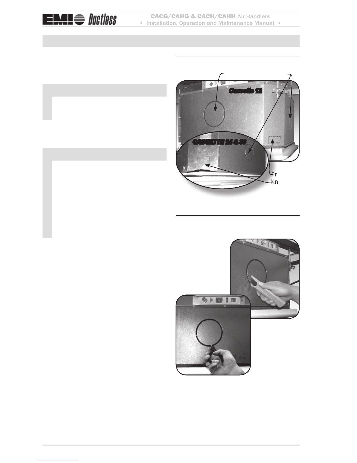
Locate the knock-out holes (1. Figure 12,
Page 14).
NOTICE
e number of knockouts varies with
unit size.
Branch duct knock-outs are 5¼”
(133mm) round.
Fresh air knockouts are:
1¼” x 2½” (32 x 64mm) rectangular •
on models 9 & 12.
3” (76mm) square on models 24 •
and 36.
Cut the black insulation around the 2.
knock-out (Figure 13, Page 14).
Snip the tabs holding the knock-out in 3.
place (Figure 13, Page 14).
Remove the metal knock-out and the 4.
black insulation behind it.
Aach the duct collars (eld supplied) to 5.
the chassis using self-drilling screws.
Repeat steps above for remaining duct 6.
work.
KnockoutsFigure 12
fresh air
knockout
branch Duct knockout
Cassette 12
CAssette 24 & 36
Cut insulation and snip out Figure 13
knockouts

CACG/CAHG & CACH/CAHH
Air Handlers
• Installation, Operation and Maintenance Manual •
P/N 240008108, Rev. B [082509] 15
Refrigerant Piping
CAUTION
Avoid piping on wet and rainy days.•
Use only clean, refrigeration-grade •
copper tubing.
Use tubing benders to guard against •
kinking.
Be certain no burrs remain on the •
ings.
Cap ends of lines until ready for con-•
nections. Be certain that plastic end
caps remain in place when inserting
through wall openings.
Insulate the suction and condensate •
lines all the way to the cassee.
Isolate tubing from transmiing vibra-•
tion to the building or unit and avoid
contact with sharp edges.
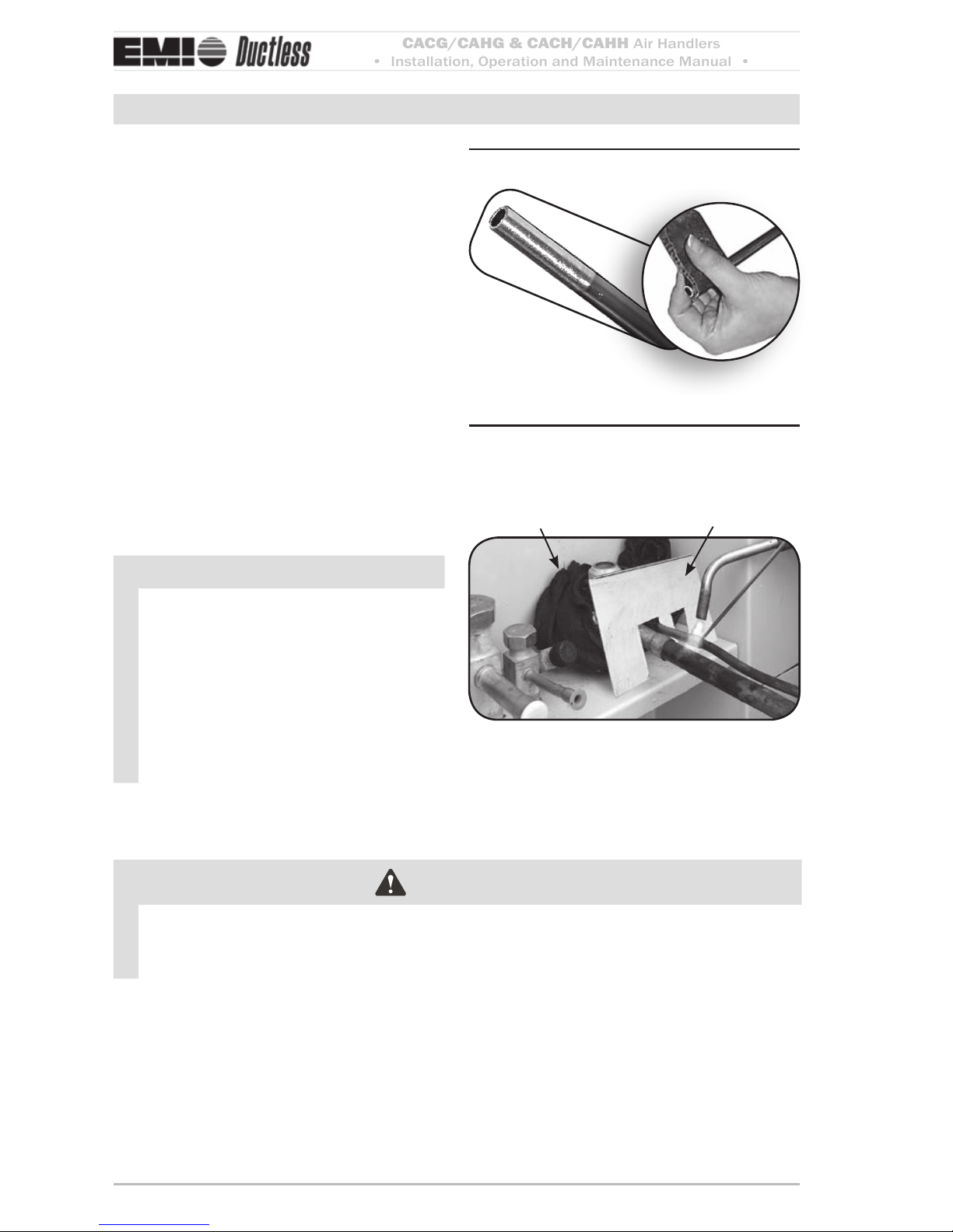
Wrap refrigeration valves with a wet •
rag “heat sink” to protect valves while
brazing. (See Figure 16, Page 16.)
DO NOT use a suction line size larger •
than the condenser service valve connection. is can harm the compressor. Install a reducer, when used, only
on the inside connection.
NOTICE
e cassee is equipped with a Flo Rater
piston expansion device. Connections
are sweat type.
Piping connections at unitFigure 14
suction line liquid line
(When a reducing bushing is required, install
only at the indoor suction-line connection.)
Line sizing
Size lines per (1. Table 11, Page 60).
e suction line size must match the con-2.
denser service valve connection.
When matching the model 24 with an a.
18,000-Btuh condenser, you must use
a 5/8-inch suction line, with a reducer
installed as shown in (Figure 14,
Page 15).
CACG/CAHG & CACH/CAHH
Air Handlers
• Installation, Operation and Maintenance Manual •
Comfort where it counts 16 P/N 240008108, Rev. B [082509]
Refrigerant Piping (continued)
Clean ends of tubingFigure 15
Place wet rag “heat shield over Figure 16
valves plus a sheet metal shield
to protect paint
Wet rag heat sink
shield
Refrigerant piping
Clean the ends of tubing and insert into 1.
ings (Figure 15).
Before brazing (2. Figure 16):
Protect valves by wrapping with a wet a.
rag “heat sink” before brazing.
Use a shield to protect the paint as b.
shown. (e shield can be made from
scrap metal.)
Braze tubing into ings, using a continu-3.
ous nitrogen purge.
e suction line must be insulated the 4.
entire length with closed cell, foam tube
insulation.
Do not insulate the liquid line.5.
Connect the outdoor unit according to 6.
the instructions supplied with unit.
NOTICE
Maximum equivalent pipe run should 1.
comply with (Table 1, Page 8).
Horizontal pipe runs should be 2.
slightly inclined, so as to encourage
oil to flow in the direction of the
compressor, for beer oil return.
Good refrigeration practices must be 3.
employed to ensure the correct pressure drop and good oil return.
CAUTION
Pressure test all eld installed piping with nitrogen. Using a suitable vacuum pump,
evacuate the tubing and indoor unit to 500 microns or less, with service valves remaining
front seated (closed).
CACG/CAHG & CACH/CAHH
Air Handlers
• Installation, Operation and Maintenance Manual •
P/N 240008108, Rev. B [082509] 17
Refrigerant Piping (continued)
Refrigerant processing
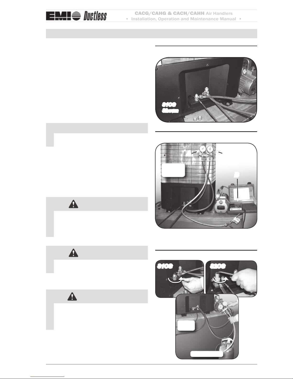
Aach manifold set (1. Figure 17).
Evacuate line to 500 microns or less to 2.
ensure all moisture has been removed and
there are no leaks.
Once certain of a good evacuation and 3.
leak free joints, back-seat the valves
(counter-clockwise) to open and allow
factory charge to ll lines and indoor unit
(Figure 18, Page 17).
NOTICE
Refer to refrigerant charge table for specied charge.
Use only R410A refrigerant. Add and
4.
remove only liquid, never vapor.
Charge to proper weight, charge based on 5.
feet of interconnect (Figure 19, Page 17).
See tables on page 18.
CAUTION
Refer to the charts in the condenser
manual to “fine tune” the refrigerant
charge.
CAUTION
Charging should be done with a dial-acharge or weighed in with a scale.
WARNING
It is illegal to discharge refrigerant into
the atmosphere. Use proper reclaiming
methods & equipment when installing
or servicing this unit.
Manifold set connections at unitFigure 17
s1CG
shown
Manifold set up for evacuationFigure 18
A C
B
s1CG
shown
ManifoldA Vacuum pumpB
Micron gageC
Charging the unitFigure 19
s2CGs1CG
Refrigerant
s1CG
shown
CACG/CAHG & CACH/CAHH
Air Handlers
• Installation, Operation and Maintenance Manual •
Comfort where it counts 18 P/N 240008108, Rev. B [082509]
S1CG/S1HG and top discharge R410A refrigerant charge table
Table 4
(CAC_ refers to CACG/CACH; CAH_ refers to CAHG/CAHH)
Condenser
Evaporator
pairing
Line charge
per foot
Factory
charge
Top discharge, Multi-zone
S1CG9
S1HG9
CAH_9
.25 oz/ft
(23 g/m)
39.50
51.25
Circuit capacity
Line charge
per foot
Factory
charge
S1CG2
S1HG2
CAH_12
.25 oz/ft
(23 g/m)
33.75
45.75
S1CG8
S1HG8
CAH_24
.64 oz/ft
(59 g/m)
62.25
63.00
09 (9,000 Btuh)
.25 oz/ft
(23 g/m)
41
S1CG4
S1HG4
CAH_24
.64 oz/ft
(59 g/m)
63.00
74.00
12 (12,000 Btuh)
.25 oz/ft
(23 g/m)
35
S1CG3 CAC_36
.64 oz/ft
(59 g/m)
97.50 18 (18,000 Btuh)
.25 oz/ft
(23 g/m)
65
S1CG6 CAC_36
.64 oz/ft
(59 g/m)
110.00 24 (24,000 Btuh)
.25 oz/ft
(23 g/m)
63
S2CG/S2HG R410A refrigerant charge table
Table 5
Condenser
Evaporator
pairing
Line charge
per foot
Factory
charge
Condenser
Evaporator
pairing
Line charge
per foot
Factory
charge
S2CG99
S2HG99
(2)
CAH_09
.25 oz/ft
(23 g/m)
40/40
51/51
S2CG92
S2HG92
(1) CAH_09 +
(1)CAH_12
.25 oz/ft
(23 g/m)
40/34
51/46
S2CG22
S2HG22
(2)
CAH_12
.25 oz/ft
(23 g/m)
34/34
46/46
Refrigerant Processing
NOTICE – to find charge adjustment
To nd the charge adjustment and system charge for any evaporator and tubing 1.
length:
Line Adjustment = (Line Charge/FT) x Line Length
System Total = Factory Charge + Line Adjustment
Round to the nearest ounce and allow for gauges and hoses.2.
CACG/CAHG & CACH/CAHH
Air Handlers
• Installation, Operation and Maintenance Manual •
P/N 240008108, Rev. B [082509] 19
Final Assembly
Assembly instructions
To install the four fascia mounting bolts:1.
Remove the bolts and washers from a.
the supplied kit bag.
Put washers onto the bolts. b.
Screw the mounting bolt with washer c.
into the chassis leaving approximately
1” (25mm) to hang the fascia.
Ensure the white panel fasteners holding 2.
the fascia polystyrene are pushed rmly in
(fasteners may have loosened in transit).
Li the fascia onto the chassis mounting 3.
bolts. Align the key hole brackets with
the mounting bolts and slide the fascia
forward to lock into position.
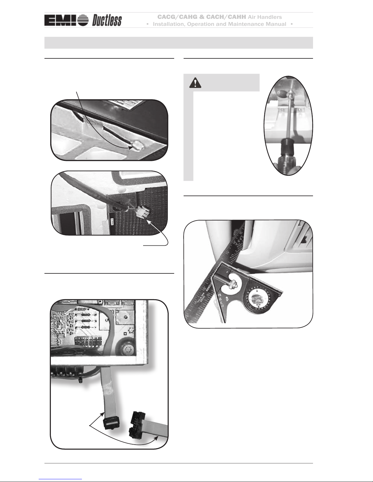
On Cassee 24 and 36 units connect the 4.
vane motor plug by plugging it into the
socket connection on the chassis.
Ensure that the polarized connector a.
(2 position) is in the proper orientation and connected.
Route the wires in a way that ensures b.
they won’t become trapped, cut, broken or chaed.
ONLY Cassette “H” models (CACH/5.
CAHH) contain a second cable connection to the control box for the Infrared
Unit Mount Control.
Ensure that the polarized (10 position) 6.
connector is in the proper orientation and
connected.
Route the wires in a way that ensures that 7.
they won’t become trapped, cut, broken,
or chaed (Figure 22, Page 19).
e fascia can now be tightened up to the 8.
Cassee chassis. make sure a good seal is
obtained between fascia and chassis, this
is necessary to prevent recirculation.
With lter(s) in place, the inlet grille(s) 9.
can now be installed onto the fascia.
Mounting boltsFigure 20
White panel fasteners must be Figure 21
pushed in
Wire routingFigure 22
CACG/CAHG & CACH/CAHH
Air Handlers
• Installation, Operation and Maintenance Manual •
Comfort where it counts 20 P/N 240008108, Rev. B [082509]
Final Assembly (continued)
Connect vane motor plug into Figure 23
socket on chassis
female vane motor plug on
chassis
Male vane motor plug on fascia
Connect infrared unit cable (“H” Figure 24
units only)
red stripe is
Conductor #1
Polarized
10 Position
Connector
Secure fascia to chassisFigure 25
CAUTION
DO NOT over-tight-
en the bolts is
could cause damage
to the fascia and drain
pan.
Adjust louver position to 30°
Figure 26
from plumb
 Loading...