

EMI S1CV, 550002575 Installation Instructions Manual
!
S1CV
Shown
WARNING
Electrical shock hazard. Improper installation
could result in death or serious injury. Read this
instructions and understand all requirements before
beginning installation. Installation is not complete
until appliance operation is verifi ed per Installation,
Operation & Maintenance Manual provided with unit.
[for 9,000-24,000 Btu 208/230V ]
Part
Number
240001773
207000010
INVERTER S1CV
CRANKCASE HEATER
KIT # 550002575
KIT #550002575
Description QTY
Crankcase Heater - 208/230V
Wire Ties
1
5
!
WARNING
Electrical shock hazard. Turn OFF electrical power
supply at service panel. Failure to do so could result
in death or serious injury.
Kit installation shall be completed by a qualifi ed
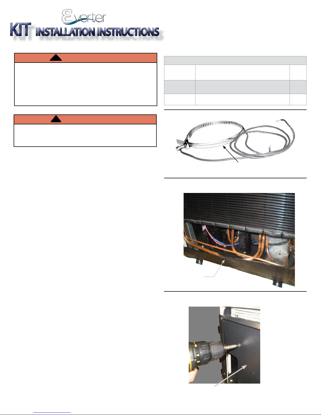
Figure 1 - Crankcase Heater
service agency.
This kit is required for cooling operation below 60° F
(15° C).
Tools
• Screwdriver
• 5/16” Nut-driver
• Needle Nose Pliers
Figure 2 - Remove Front Panel
Crankcase Heater
Installation Instructions
1.
Disconnect Power Supply.
2.
Remove front panel. See Figure 1.
A. Remove screws from front of left and right side
panels.
B. Remove screws from front of panel.
C. Remove front panel forward to access compressor
compartment.
3.
Access electrical connections and wiring diagram:
A. Remove all screws on back panel adjacent to line
set side. See Figure 2.
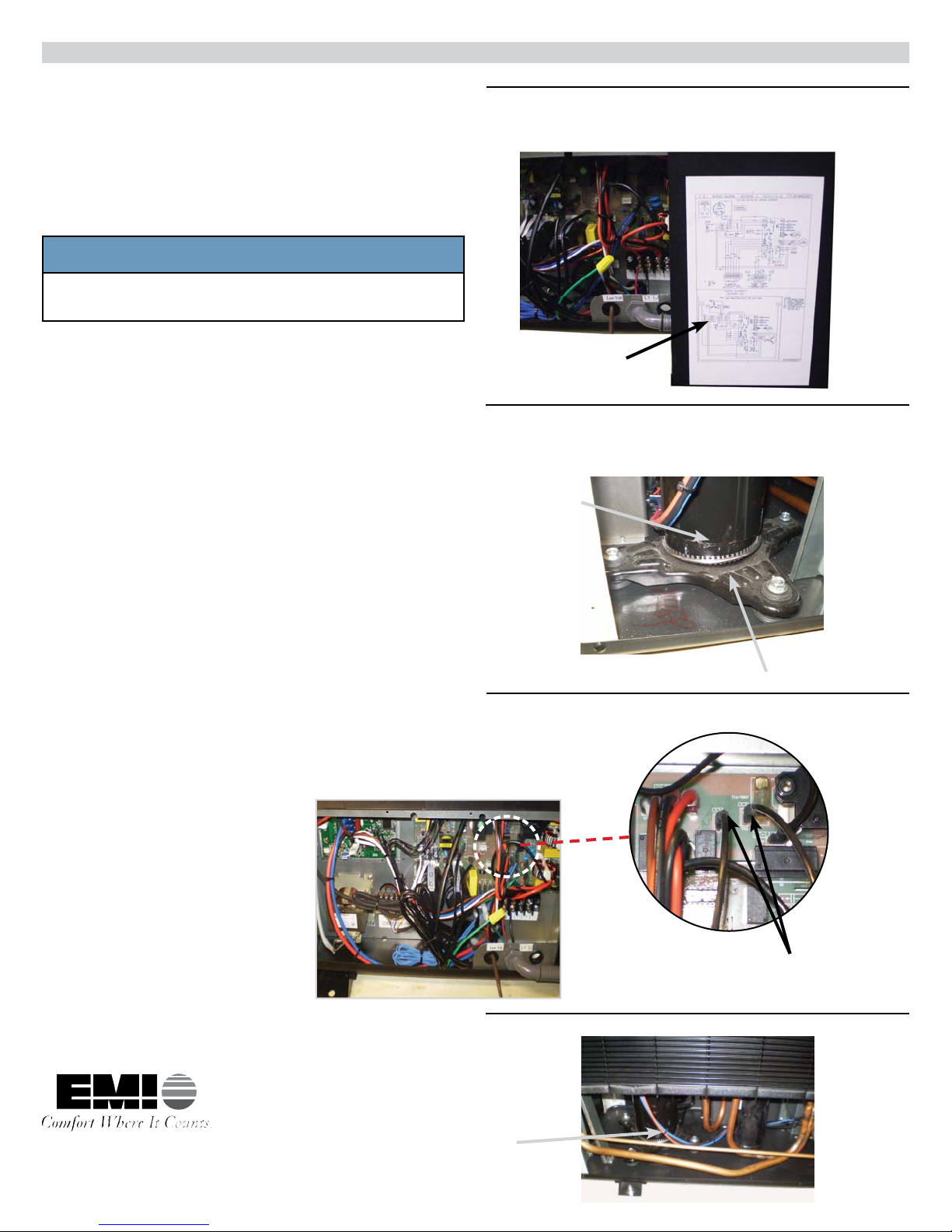
B. Remove control box cover to access electrical
connections and wire diagram on inside of panel.
See Figure 3.
Remove panel by
bringing forward
Figure 2 - Back Panel
BACK PANEL
S1CV
Shown
240009304 REV B [7/2012]
CRANKCASE HEATER KIT INSTRUCTIONS
S1CV
4.
Install heater around base of compressor. Tighten with
5/16” socket. See Figure 4.
5.
Route Crankcase Heater wires through back panel to
make terminations on control board (connect wires of
Crank Case Heater to CCH labeled terminals). CCH is
not polarized. See Figure 5.
NOTICE
Push connectors fully onto spade terminals. Use of
needle nose pliers is recommended.
6.
Wire tie loose wires. See Figure 6.
7.
Replace panels.
Figure 3 - Wire Diagram Inside Control Box
Cover
Wire Diagram Inside
Control Door
8.
Re-connect power.
Figure 4 - Crankcase Heater Around Base of
Compressor
Compressor
S1CV
Crankcase Heater
Figure 5 - Crankcase Heater Wires To CCH
Terminals
ECR INTERNATIONAL Inc
2201 Dwyer Avenue, Utica, NY, USA 13501
www.ecrinternational.com
Crankcase
Heater Wires
Figure 6 - Wire Tie Loose Wires
Wire Ties
 Loading...