

Page 1

Artisan Technology Group is your source for quality
new and certied-used/pre-owned equipment
• FAST SHIPPING AND
DELIVERY
• TENS OF THOUSANDS OF
IN-STOCK ITEMS
• EQUIPMENT DEMOS
• HUNDREDS OF
MANUFACTURERS
SUPPORTED
• LEASING/MONTHLY
RENTALS
• ITAR CERTIFIED
SECURE ASSET SOLUTIONS
SERVICE CENTER REPAIRS
Experienced engineers and technicians on staff
at our full-service, in-house repair center
Instra
Remotely inspect equipment before purchasing with
our interactive website at www.instraview.com
Contact us: (888) 88-SOURCE | sales@artisantg.com | www.artisantg.com
SM
REMOTE INSPECTION
View
WE BUY USED EQUIPMENT
Sell your excess, underutilized, and idle used equipment
We also offer credit for buy-backs and trade-ins
www.artisantg.com/WeBuyEquipment
LOOKING FOR MORE INFORMATION?
Visit us on the web at www.artisantg.com for more
information on price quotations, drivers, technical
specications, manuals, and documentation
Page 2

Programming Manual
Control and Power Unit
TMP
Emhart Teknologies
TUCKER GmbH, Max-Eyth-Straße 1, 35394 Gießen
Tel.: 0641/405-0; Fax.: 0641/405-383; Mail: Info@tucker.de
Artisan Technology Group - Quality Instrumentation ... Guaranteed | (888) 88-SOURCE | www.artisantg.com
Page 3

Table of Contents
1. Menu Access and Selection 1
1.1 Sub-Menu “Keyboard Functions“ 2
1.2 Sub-Menu “Weld Parameter Monitor“ 3
1.3 Sub-Menu “Programming“ 5
1.3.1 Functions Menü “Programming Weld Parameters“ 5
1.3.2 Functions Menü “Programming Output/Feeder“ 8
1.4 Sub-Menu “Statistics“ 9
1.4.1 “Fault Memory“ 9
1.4.2 “WOP-Memory“ 11
1.4.3 “Weld Output Statistics“ 13
1.4.4 “Weld Program Statistics“ 14
1.4.5 “Maintenance“ 15
1.5 Sub-Menu “Clear Fault Condition“ 17
1.6 Sub-Menu “Status Weld Sequence“ 20
1.7 Sub-Menu “Status Customer Interface“ 22
1.8 Sub-Menu “Status Feeder/Stud Divider“ 24
1.9 Sub-Menu “Status TMP ....“ 25
1.10 Sub-Menu “Functions“ 27
1.10.1 Functions Menu “Display System Configuration“ 27
1.10.2 Functions Menu “Test Mode Cycle Functions“ 28
1.10.3 Functions Menu “Test Mode Outputs Interface“ 30
1.10.4 Functions Menu “Test Mode Weld Process“ 31
1.10.5 Functions Menu “TEST Mode Power Supply“ 32
1.11 Sub-Menu “Warnings“ 34
1.12 Sub-Menu “Extended Functions“ 35
1.12.1 Functions Menu “System Parameters“ 36
1.12.2 Functions Menu “Mechanical Parameter“ 37
1.12.3 Functions Menu “Weld Program“ 40
1.12.4 Functions Menu “Copy Programs“ 42
1.12.5 Functions Menu “Clear Funktions“ 44
1.12.6 Functions Menu “ZCPU System Test“ 45
1.12.7 Functions Menu “De/Activate Program“ 46
1.12.8 Functions Menu “Stud Length Detection“ 47
1.12.9 Functions Menu “Set Date and Time“ 49
Appendix A Main Menu TMP Systemsoftware 50
Appendix B DIP-Switch information 61
Appendix C Fault Messages 62
Appendix D Error Memory Messages 79
Appendix E Messages regarding pilot arc voltage 80
Artisan Technology Group - Quality Instrumentation ... Guaranteed | (888) 88-SOURCE | www.artisantg.com
Page 4

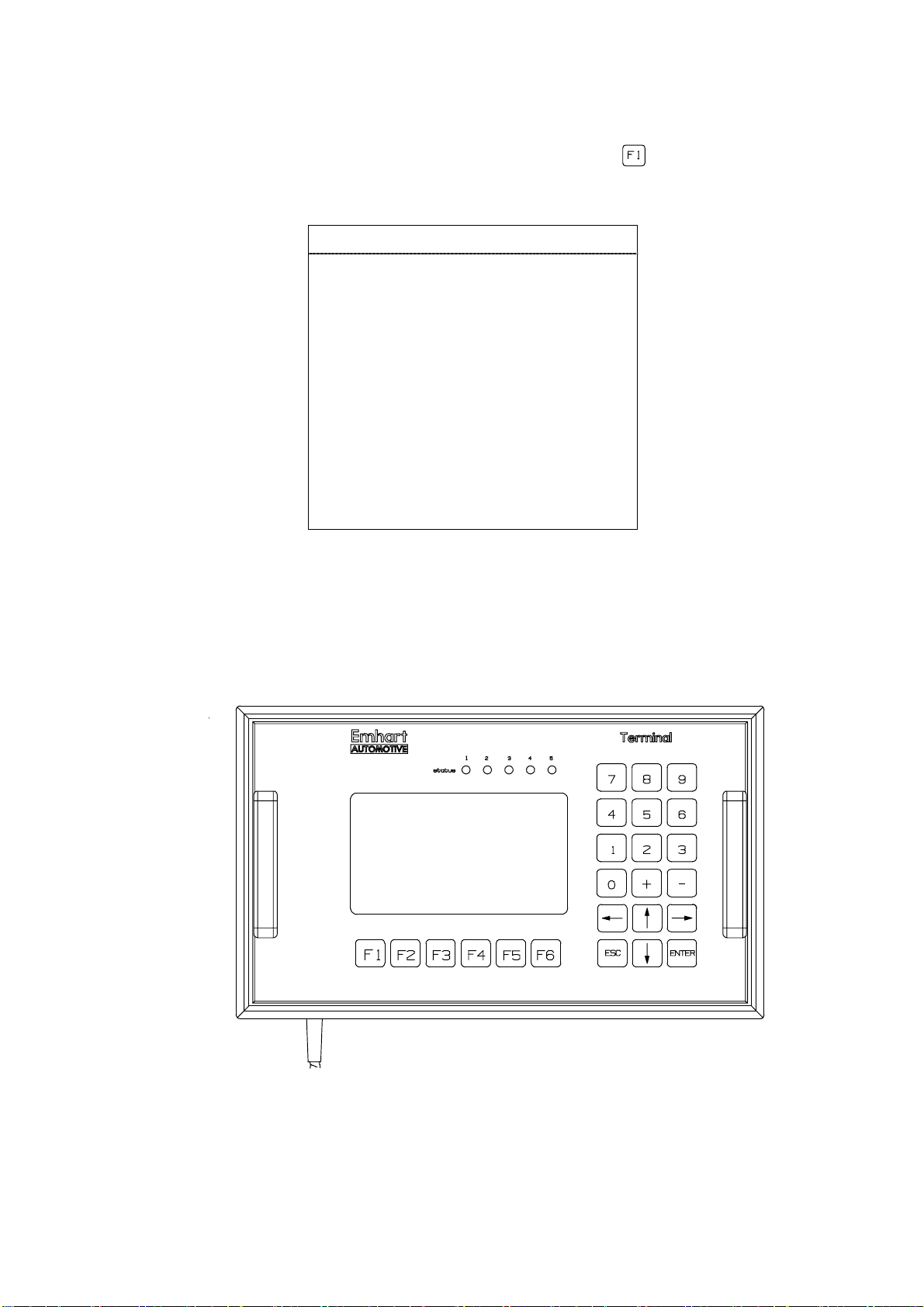
1. Menu Access and Selection
When switching the TMP weld unit on the screen display will be activated. The
TMP will identify itself by presenting unit and peripherals types as well as the
corresponding software versions.
Software version 1 Software version 2
T U C K E R #########
System software V ##.##
Keypad/Display V ##.##
Central CPU V ##.##
SMPS V ##.##
Interface ########### V ##.##
Output 1 #### / #### V ##.##
Output 2 #### / #### V ##.##
Output 3 #### / #### V ##.##
Output 4 #### / #### V ##.##
Output 5 #### / #### V ##.##
<F1..F5> <ESC>
System software V ##.##
Keypad/Display V ##.##
Central CPU V ##.##
SMPS V ##.##
Interface ########### V ##.##
Output 1 #### / #### V##.## LM V ##.##
Output 2 #### / #### V##.## LM V ##.##
Output 3 #### / #### V##.## LM V ##.##
Output 4 #### / #### V##.## LM V ##.##
Output 5 #### / #### V##.## LM V ##.##
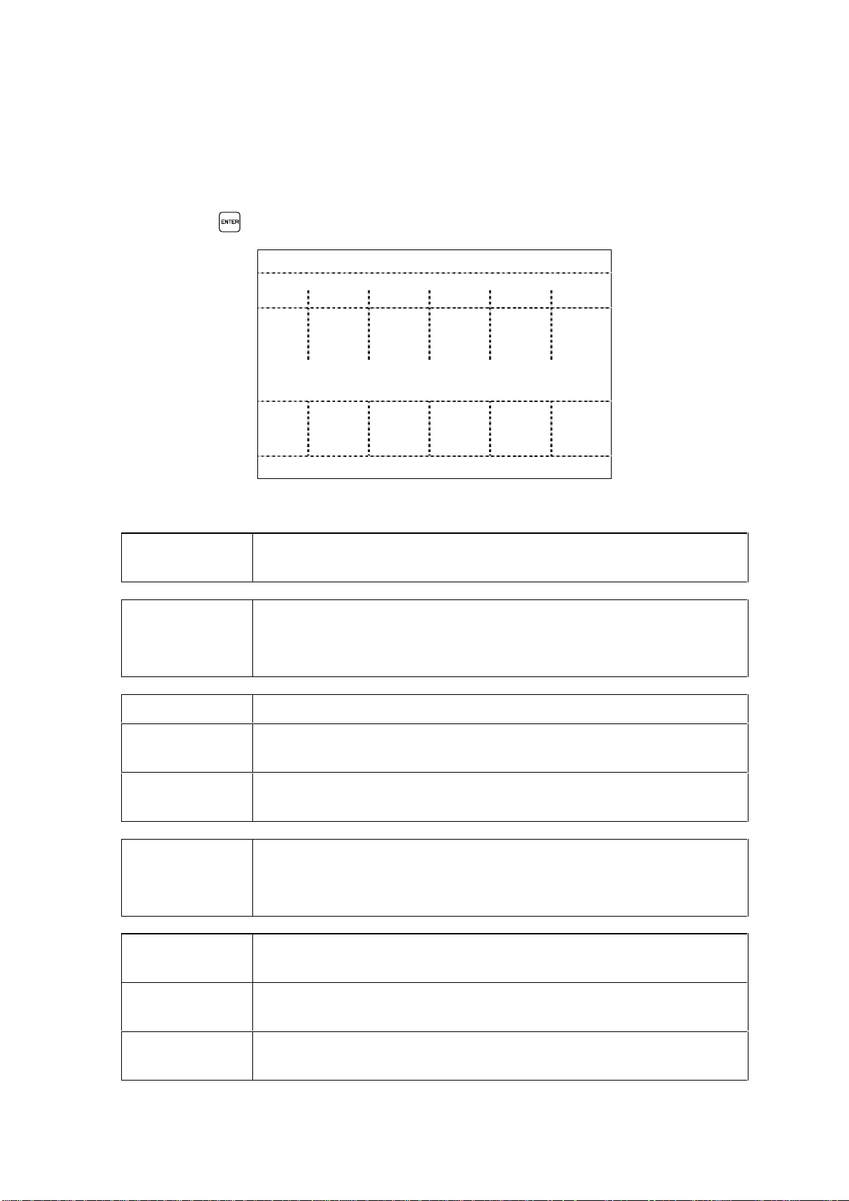
Now please press the key to open the main menu.
OPERATION
Weld parameter monitor
Programming
Statistics
Fault reset
Status weld sequence
Status customer interface
Status Feeder/Stud-Divider
Status TMP
Functions
Warnings
T U C K E R #########
<F1..F5> <ESC>
<↓↑> <ENTER> <F1..F5>
As soon as the main menu appears on the screen the sub-menues listed can be
selected.
1. Position the cursor with the direction keys and on the corresponding
submenu and confirm your selection with .
2. Sub-menus with alterable contents may also be selected by pressing one of the
function keys listed below directly.
• Function key : open main menu "Function Keys"
• Function key : open main menu "OPERATION"
• Function key : open main menu "Programming"
• Function key : open main menu "Monitor Parameters"
• Function key : open main menu "Reset Fault"
• Function key and open changing over languages.
1
Artisan Technology Group - Quality Instrumentation ... Guaranteed | (888) 88-SOURCE | www.artisantg.com
Page 5
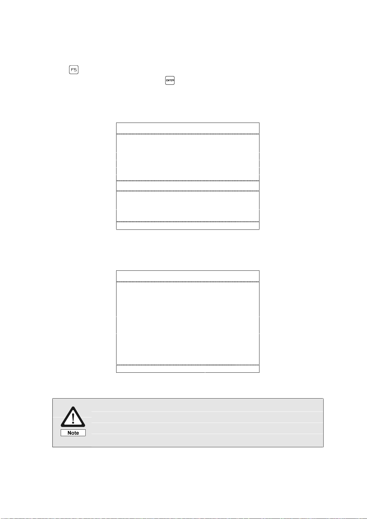
1.1 Sub-Me nu “Keyboard Functions“
The sub-menu “Keyboard Functions“ is selected via the key. This menu informs
the user about the configuration of the operation control keys.
Key Functions
F1 - Display key functions
F2 - Main menu
F3 - Programming
F4 - weld parameter monitoring
F5 - fault reset
F6 - Release Manual Functions
ESC - ESCAPE, abort
ENT - ENTER, confirmation
0..9 - input SKK/PK, program no.
+ - - change, set/reset values
<↓↑> - select menu, value
Exit the menu by pressing any key.
Display- and Control Panel
2
Artisan Technology Group - Quality Instrumentation ... Guaranteed | (888) 88-SOURCE | www.artisantg.com
Page 6
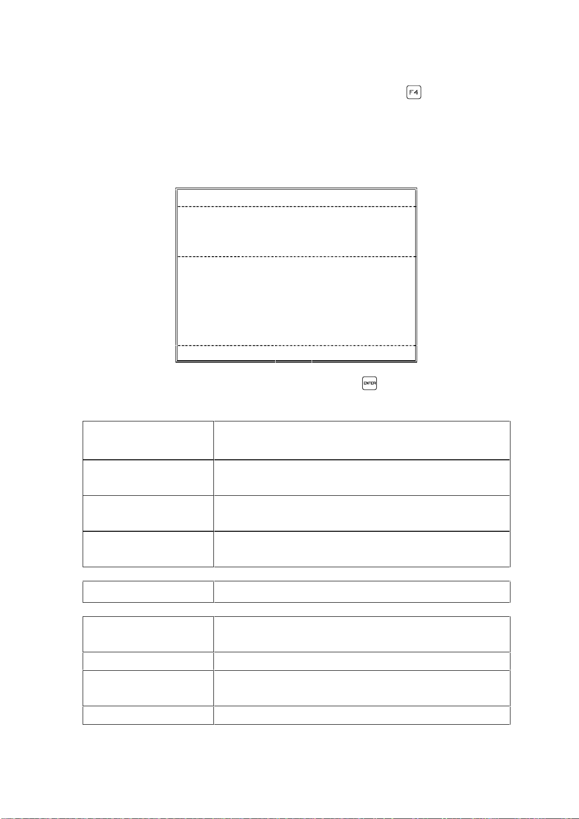
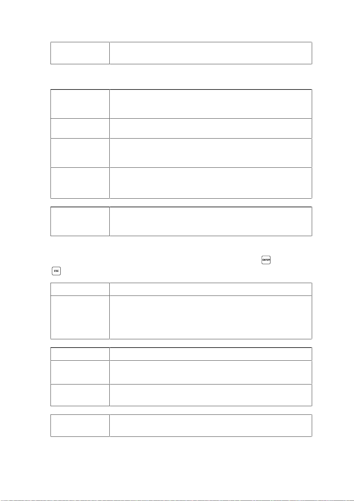
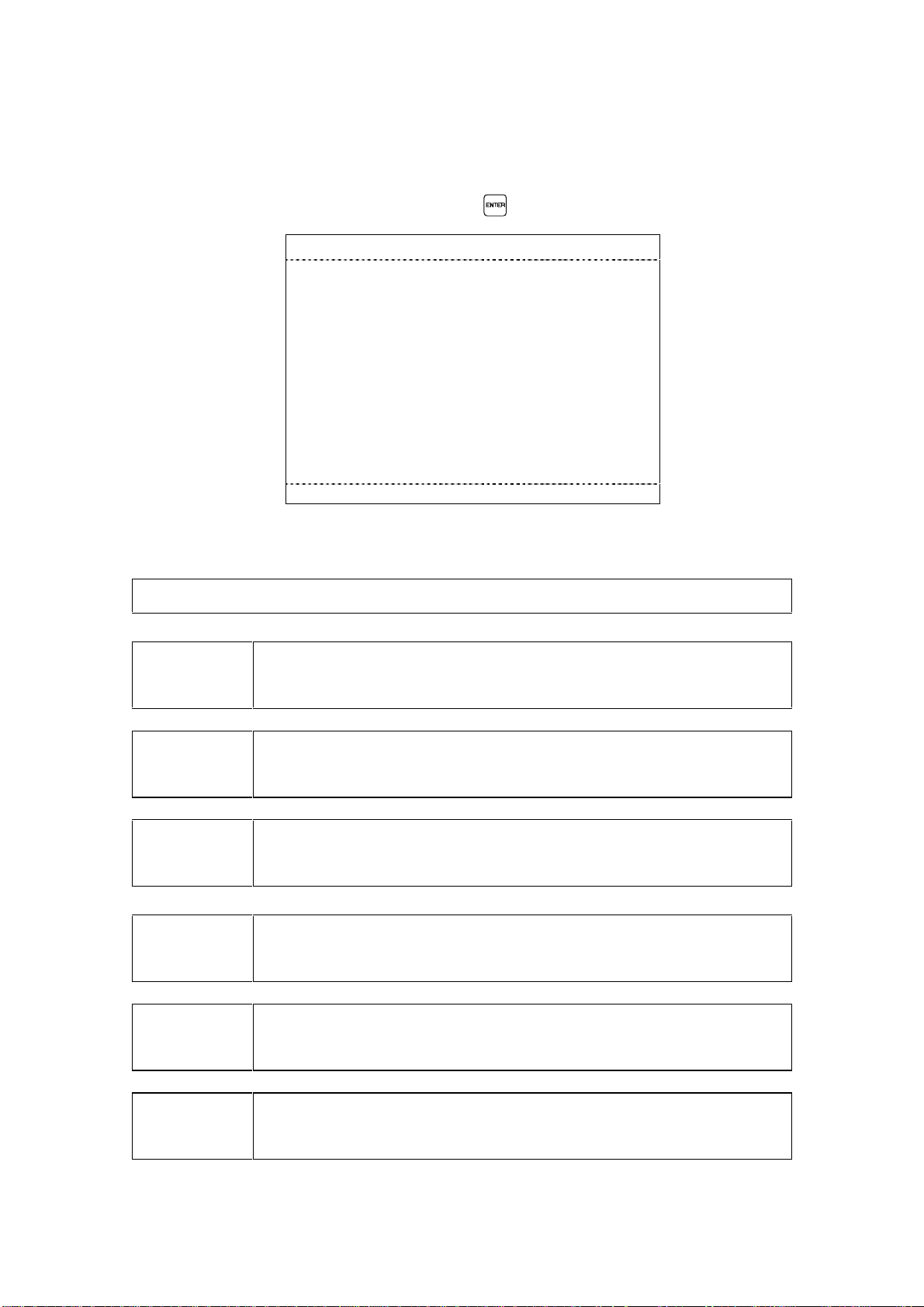
1.2 Sub-Menu “Weld Parameter Monitor“
Having selected the sub-menu "Weld Parameter Monitor" using or through the
direction keys the cursor will move to the first menu line requesting selection of th e
TMP output (1-5) to be monitored as well as the program no. (1-27) of the weld
program to be monitored.
Remark: Output "0" described below has a special function.
Weld parameter monitor
SKK/PK outlet : # Program.No.:. . . . ###
Weld part ident : ################
Autoplunge : #### Optimization. . . . .####
Ref +tol -tol Act
Vp ## ## ## ## V #
Vw ## ## ## ## V #
Iw #### ### ### #### A #
tw ### ## ## ###,# ms #
td ##,# ##,# ms #
#Lift #,## ,## ,## #,## mm #
Fault : ################### #################
< 0..5> <ENTER> <F1..F5> <ESC>
Select output and program number and confirm with . The individual menu lines
of the display signify the following:
SKK/PK Output 0 The parameters of the weld tool that welded last will be
displayed in the table.
SKK/PK Output 1-5 The parameters of the last weld of the selected weld
tool will be listed.
Progr.-Nr. 0 The parameters of the last weld program will be
displayed in the table.
Progr. Nr. 01 - 127 The parameters of the selected weld program will be
displayed in the table.
Weld part ident Display of the program ident for the weld part.
Autoplunge: Yes
The deenergization time of the solenoid will be auto-
(tw = we ld time)
matically adjusted to the reference stud drop time.
Autoplunge No Automatic autoplunge is not activated.
Optimization: Yes
(Up to max. 800A/60ms)
Automatic adjustment of the weld curr ent Iw / wel d time
tw when welding through impurities on work surfaces.
Optimization: No No optimization of weld current (Iw) and weld time (tw).
3
Artisan Technology Group - Quality Instrumentation ... Guaranteed | (888) 88-SOURCE | www.artisantg.com
Page 7
Ref Preset value set according to weld program.
+ tol Positive tolerance. "0" selections will not be monitored.
- tol Negative tolerance. "0" selections will not be monitored.
Act Actually measured weld parameters of last weld.
Vp [V]
Arc voltage in pilot current phase. *
Vw [V] Arc voltage in weld current phase.
Iw [A] Weld current.
tw [ms] Weld time.
td [ms] Stud drop time.
Lift [mm] Lift distance.
An exclamation mark before the text Lift signifies that the
stud length measurement function for SD2 has been
deactivated in terms of position.
* Some voltage values are of particular importance (see Annex E).
Fault The fault will be displayed that has occu red during welding.
Possible fault indications are:
None Weld cycle without fault.
SMPS Defect within SMPS, welding was stopped.
Lift Cycle On Fault when enabling the solenoid.
No arc Voltage Defective lift; short circuit in weld circuit.
Short circuit weld The last weld performed was a short circuit operation.
Lift Cycle Off Fault when disabling the solenoid.
Drop Time
Monitoring time in weld sequence was exceeded.
Timeout
No Weld Current The last weld performed was an open circuit operation.
Faults will be recorded under a fault nu mber in the fault mem or y.
Selecting the function keys .. will open the corresponding sub-menu. By
pressing or you will access the main menu.
4
Artisan Technology Group - Quality Instrumentation ... Guaranteed | (888) 88-SOURCE | www.artisantg.com
Page 8
1.3 Sub-Menu "Programming"
Please note that opening of the sub-menu "Programming" is
Note
The sub-menu "Programming" is to be selected for programming of the weld
parameters as well as the weld outputs and the specific feed times.
Direct access will be accomplished via the function key or by positioning the
cursor on the second line of the main menu and pressing .
Programming
Weld parameters
Output/feeder
exclusively reserved for authorized and qualified personnel.
<↓↑> <ENTER> <F1..F5> <ESC>
1.3.1 Function Menu "Programming Weld Parameters"
The function menu "Programming Weld Parameters" is selected via the and
keys and confirmed via .
Programming weld parameters
Output No . . . . . . . . . . . : #
Weld programm no . . . . : ###
Weld programm activ. . . ####
Weld diameter. . . . . . . . . #####
Workpiece gauge . . . . . . #####
Workpiece coating . . . . . ########
Energy adjustment . . . . . ### %
<1..9> <↓↑> <+,-> <ENTER> <F1..F5> <ESC>
The significance of the indivi dual menu l ines i s descri bed on the foll ow i ng pag es.
5
Artisan Technology Group - Quality Instrumentation ... Guaranteed | (888) 88-SOURCE | www.artisantg.com
Page 9
Output No.: The output number defines the weld tool which will be
addressed based on the TMP connector configuration.
When indicating the output the follow i ng operati on modes ar e to be differentiated:
Standard
operation
In standard operation (feeder - SKK/PK) the output no. must
be entered corresponding to the TMP connector configuration.
For example: "TMP-pin 1 - feeder 1 - SKK/PK no. 1".
SD2 operation
When using a 2-way stud divider "SD2" only output no. 1 is to
be addressed.
SD5 operation
When using a 5-way stud divider the output no. is to be
entered corresponding to the "SD5" configuration. For
example: "SD5 connector configuration 3 - SKK no. 3".
SD5 opera tion When using a 5-way stud divider the output no. is to be
entered corresponding to the "SD5" configuration. For
example: "SD5 connector configuration 3 - SKK no. 3".
Weld Program
No.
For each weld task a specific weld program should be
available which is to be addressed via the corresponding
program no. (1 - 127).
Enter a number between 1 and 5 for the weld output as well as between 1 and 127
for a weld program via the numerical keypad and confirm with or press
to exit the input mode.
Yes External program selection enabled.
No External program selection disabled.
Remark: if no external program selection is requested only
weld program 1 may be activated for the corresponding
output.
Weld diameter Selection of weld flange diameter.
Flange diameter Selection of flange diameter in a range from 2 mm - 8 mm
(step size: 1 mm).
SWB10 When welding T-studs with a l ength of 3,8 m m and a flang e
diameter of 3 mm the TUCKER-name SWB10 is to be entered.
Workpiece
Gauge
Selection of sheet thickness of work surface: 0,8 mm, 1,2 mm,
2 mm or >2 mm.
6
Artisan Technology Group - Quality Instrumentation ... Guaranteed | (888) 88-SOURCE | www.artisantg.com
Page 10

Coating Selection of work surface coating.
none Untreated work surface.
galvanized Galvanized work surface.
Energy adjustment Weld ener gy adjustment in a range from -50% - +50%
(step size: 5%).
Programming is to be executed by the and keys. The selections of the
individual parameters can be either confirmed with or rejected with .
By pressing the or the key the cursor will move to the field "output no." and
enables further programming. By pressing you will return to the sub-menu
"programming".
7
Artisan Technology Group - Quality Instrumentation ... Guaranteed | (888) 88-SOURCE | www.artisantg.com
Page 11

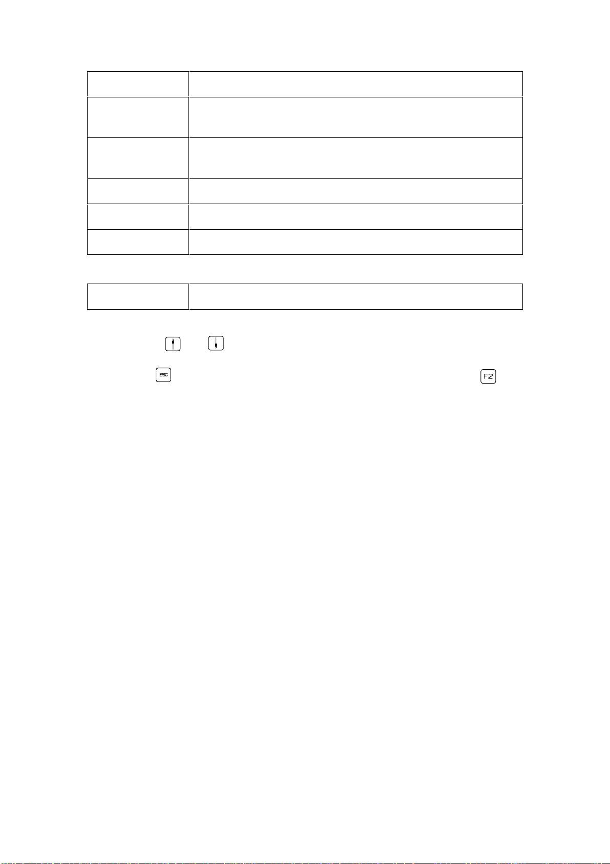
1.3.2 Function Menu "Programming Output / Feeder"
The function menu "Programming Output / Feeder" will be selected via the
and keys in the sub-menu "Programming" and confirmed with .
Programming output/feed time
Weld output No . : #
Output active....... ####
Feed time............. #### ms
<1..9> <↓↑> <+,-> <ENTER> <F1..F5> <ESC>
Weld output no. The weld output no. will define the weld tool which will be
addressed based on the TMP connector configuration.
Yes The output of the TMP weld unit is activated.
No The output of the TMP weld unit is not activated.
Feed time The time between feeding signal and arrival of the stud in the
stud receiver is to be selected in a range from 50 ms - 1600 ms.
Remark: Programming is to be performed via the numerical keys, the and
keys as well as the and keys.
8
Artisan Technology Group - Quality Instrumentation ... Guaranteed | (888) 88-SOURCE | www.artisantg.com
Page 12

1.4 Sub-Menu "Statistics"
The sub-menu "Statistics" will be selected by positioning of the cursor on the third
line of the main menu and by presing the key. The sub-menu "Statistics"
contains sub menus in which information on faults, welds and maintenance are
recorded.
Statistics
Fault memory
WOPs memory
Weld output statistics
Weld program statistics
Maintenance
<↓↑> <ENTER> <F1..F5> <ESC>
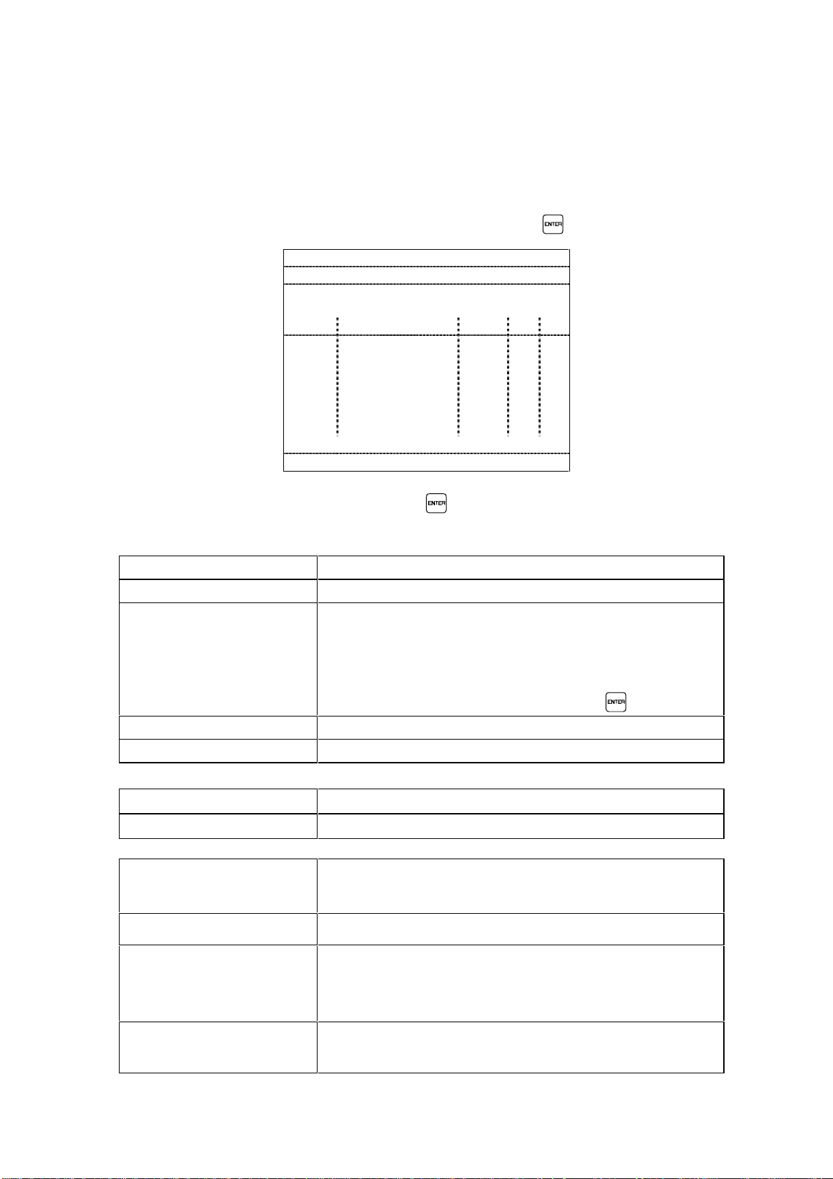
1.4.1 Sub-Menu "Faul t Memory"
By positioning the cursor on the first line of the sub-menu "Statistics" and then
pressing the key you can access the "Fault Memory" screen.
Fault memory Fault no. ###
O Prg Fault type No. Date Time
# ### ########### ### ##.##.## ##:##:##
# ### ########### ### ##.##.## ##:##:##
# ### ########### ### ##.##.## ##:##:##
# ### ########### ### ##.##.## ##:##:##
# ### ########### ### ##.##.## ##:##:##
# ### ########### ### ##.##.## ##:##:##
Fault description:
<↓↑> <F1..F5> <ESC>
The individual menu lines will be described on the following page:
Fault Memory All faults of the equipment will be recorded.
Fault No. Number of fault on which the cursor is positioned.
9
Artisan Technology Group - Quality Instrumentation ... Guaranteed | (888) 88-SOURCE | www.artisantg.com
Page 13
A
Display of output 1 - 5.
Prg
If faults occur during the weld sequence the weld program
will be displayed.
Fault Type
Information at which component the faul t occurr ed
(unit / SKK/PK / feeder / stud divider).
No.
Date
Time
No. of fault message.
Date of fault.
Time of fault.
Fault Description Short fault description (according to current cursor position).
With the keys and you can alternately display the fault memory.
By pressing you will return to the sub-menu "Statistics". By pressing you
will return to the main menu.
Trouble Shooting Information:
• Faults can be reset based on the information "Fault Messages".
• Faults which can not be reset on location through the listed remedial measures
require the replacement of the weld unit.
• Faults occurred at a peripheral unit are to be remedied based on the information
given in the corresponding operating manual.
• Faults will be reset in the menu "Clear Fault Cond ition".
10
Artisan Technology Group - Quality Instrumentation ... Guaranteed | (888) 88-SOURCE | www.artisantg.com
Page 14
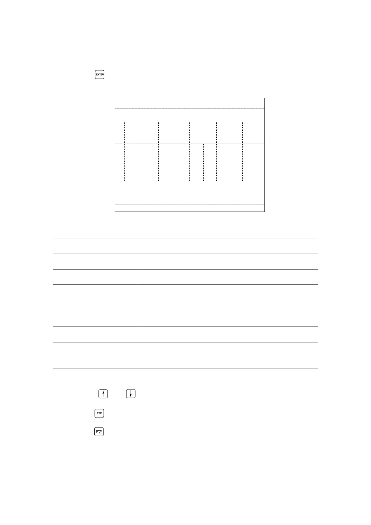
1.4.2 "WOP- Memory"
The "WOP-Memory" contains messages and information about welds out of
tolerance (Weld Outside Parameter = WOP)
The "WOP-Memory" screen can be accessed by positioning of the cursor on the
second line of the sub-menu "Statistics" and by pressing .
WOP-mem Outlet:# Prog:### Page:###
Weld part ident : ################
Date........ ##.##.## Time .......... .##:##:##
Autoplunge. ..#### Optimization.... ...####
Ref +tol -tol Act
Vp ## ## ## ## V #
Vw ## ## ## ## V #
Iw #### ### ### #### A #
tw ### ## ## ###,# ms #
td ##,# ##,# ms #
#Lift #,## ,## ,## #,## mm #
Fault : #################################
<0..5> <↓↑> <ENTER> <F1..F5> <ESC>
Select output number and confirm with . The individual menu lines of the
display signify the following:
WOP-Memory Record for all welds out of tolerance.
Weld part ident Display of the program ident for the weld part
O Those outputs for which WOP‘s are to be displayed
can be entered with the numerical keys 1 - 5.
With the key 0 all WOP‘s will be displayed in
sequence of their occurrence.
The selection must be confirmed with .
Prog. Display of current weld program.
Page Display of current page.
Date Date when WOP occurred.
Time Time when WOP occurred.
Autoplunge: Yes
(tw = we ld time)
The de-energization time of the solenoid will be auto-
matically adjusted to the reference stud drop time.
Autoplunge: No
Optimization: Yes
(up to max. 800A/60ms)
Automatic autoplunge was not activated.
An automatic adjustment of the weld curr ent Is / wel d
time ts when welding through impur iti es on w ork
surface was performed.
Optimization: No No optimization of weld current lw and weld time tw
performed.
11
Artisan Technology Group - Quality Instrumentation ... Guaranteed | (888) 88-SOURCE | www.artisantg.com
Page 15

Ref
Preset value set according to weld program.
+ tol
- tol
Act
Positive tolerance. "0" selections will not be measured.
Negative tolerance. "0" selections will not be measured.
Actually measured weld parameters of the last weld
performed.
Vp [V]
Vw [V]
lw [A]
tw [ms]
td [ms]
Lift [mm]
Arc voltage in pilot current phase.
Arc voltage in weld current phase.
Weld current.
Weld time.
Stud drop time.
Lift distance.
Fault The fault will be displayed that has occured during welding.
• Possible fault messages are:
None Weld sequence without fault.
SMPS Defect within SMPS, welding was stopped.
Lift Cycle On Fault when enabling the solenoid.
No arc voltage Defective lift; short circuit in weld circuit.
Short circuit weld The last weld performed was an short circuit operation.
Lift Cycle Off Fault when disabling the solenoid.
Drop Time
Monitoring time in weld sequence was exceeded.
Timeout
No weld currentt The last weld performed was an open circuit operation.
The WOPs can be alternately displayed with the keys and .
By pressing you will return to the sub-menu "Statistics". By pressing you
will return to the main menu.
12
Artisan Technology Group - Quality Instrumentation ... Guaranteed | (888) 88-SOURCE | www.artisantg.com
Page 16
1.4.3 "Weld Output Statistics"
By positioning the cursor on the third line of the sub-menu "Statistics" and then
pressing the key you can access the memory menu "Weld Output Statistics"
screen.
Weld outlet statistics
WOP
Number of
O
WIP &WO P
1 ####### ####### # # ###### #####
2 ####### ####### # # ###### #####
3 ####### ####### # # ###### #####
4 ####### ####### # # ###### #####
5 ####### ####### # # ###### #####
Number of
WOP
repeat
lim act
Number
of faults
<F1..F5> <ESC>
auto
rep.feed
The individual menu lines signify the following:
Output Display of the output the statistics are related to.
Number of WIP & WOP Total number of welds.
Number of WOPs Total number of welds out of tolerance.
WOP repeat limit Display of programmed acceptable sequential welds
that may be out of tolerance.
Actual WOP repeat Actual number of sequential welds out of tolerance.
Number of faults Total number of faults occurred.
Auto refeed No. of studs automatically supplied due to missing
SOW-signal during internal slide rail control.
The information for the individual weld programs can be alternately displayed with
the keys and .
By pressing you will return to the sub-menu "Statistics".
By pressing you will return to the main menu.
13
Artisan Technology Group - Quality Instrumentation ... Guaranteed | (888) 88-SOURCE | www.artisantg.com
Page 17

1.4.4 "Weld Program Statistics"
By positioning the cursor on the fourth line of the sub-menu "Statistics" and then
pressing the key you can access the memory menu "Weld Program Statistics"
screen.
Weld program statistics Outlet:#
number
of
Prog
<↓↑> <F1..F5> <ESC>
WIP&WOP
####### ####### # # #####
####### ####### # # #####
####### ####### # # #####
####### ####### # # #####
####### ####### # # #####
####### ####### # # #####
####### ####### # # #####
####### ####### # # #####
number
of
WOP
WOP
repeat
lim act
auto.
rep.
feed
Select output number and confirm with . The individual menu lines of the
display signify the following:
Weld Program Statistics Statistics of welds within and out of tolerance for the
individual outputs.
Output Selection of the ouput for which statistical information
is to be displayed.
Prog Display of the program the statistics are related to.
Number of WIP & WOP T otal number of welds.
Number of WOPs Total number of welds out of tolerance.
WOP repeat limit Display of programmed acceptable sequential welds
that may be out of tolerance.
Actual WOP repeat Actual number of sequential welds out of tolerance.
Auto refeed No. of studs automatically supplied due to missing
SOW-signal during internal slide rail control.
The information for the individual weld programs WOP‘s can be alternately
displayed with the keys and .
By pressing you can select another output, by pressing again you will
return to the sub-menu "Statistics".
By pressing you will return to the main menu.
14
Artisan Technology Group - Quality Instrumentation ... Guaranteed | (888) 88-SOURCE | www.artisantg.com
Page 18
1.4.5 "Maintenance"
The "Maintenance" screen contains information about the condition of the
connected weld tools due to wear.
By positioning the cursor on the fifth line of the sub-menu "Statistics" and then
pressing the key you can access the "Maintenance" screen.
Maintenance
Collet maint. – No. welds
12345
Act. ###### ###### ###### ###### #####
Warn. ###### ###### ###### ###### #####
Fault ###### ###### ###### ###### #####
Monitor - drop time (ms)
Act. ###,# ###,# ###,# ###,# ###,#
Warn. +# -# +# -# +# -# +# -# +# -#
Fault +# -# +# -# +# -# +# -# +# -#
<F1..F5> <ESC>
The individual menu lines signify the following:
Maintenance The wear of the collet as well as the drop time of the connected
weld tools will be displayed.
Collet Maint.No. of Welds
Weld statistics will begin with assembly of new col l et.
Remark: After replacing the collet the maintenance met er must
be reset.
Act. Actual number of welds performed with a collet.
Warn. Programmed number of welds with which, when exceeded, the
corresponding maintenance warning will become active.
Fault Programmed number of welds with which, when exceeded, the
weld output will be set into fault condition.
Monitor Drop
Time (ms)
Monitoring of the mechanical parameter "stud drop time".
Remark: The difference refers to the established drop time of
the past 8 welds in relation to the programmed (!) drop time.
Act.
Deviation of actual measured stud drop time from the programmed one will be displayed.
Warn.
Programmed deviation with which, when exceeded, the corresponding maintenance warnin g will become active.
Fault
Programmed deviation with which, when exceeded, the corresponding weld output will be set to fault condition.
15
Artisan Technology Group - Quality Instrumentation ... Guaranteed | (888) 88-SOURCE | www.artisantg.com
Page 19

Maintenance Information:
• The maintenance warning will be transmitted to the customer interface and will
appear as " ! " in the corresponding field of the sub-menu " Status TMP . . . . ".
• Irrespective of the TMP unit maintenance warnings the prescribed maintenance
intervals of the unit components must be maintained.
• Information on the specific maintenance works can be read from the
corresponding operating manuals.
• Having repaired the unit components the maintenance statistics in the menu "
Clear Functions" must be reset to " 0 ".
16
Artisan Technology Group - Quality Instrumentation ... Guaranteed | (888) 88-SOURCE | www.artisantg.com
Page 20
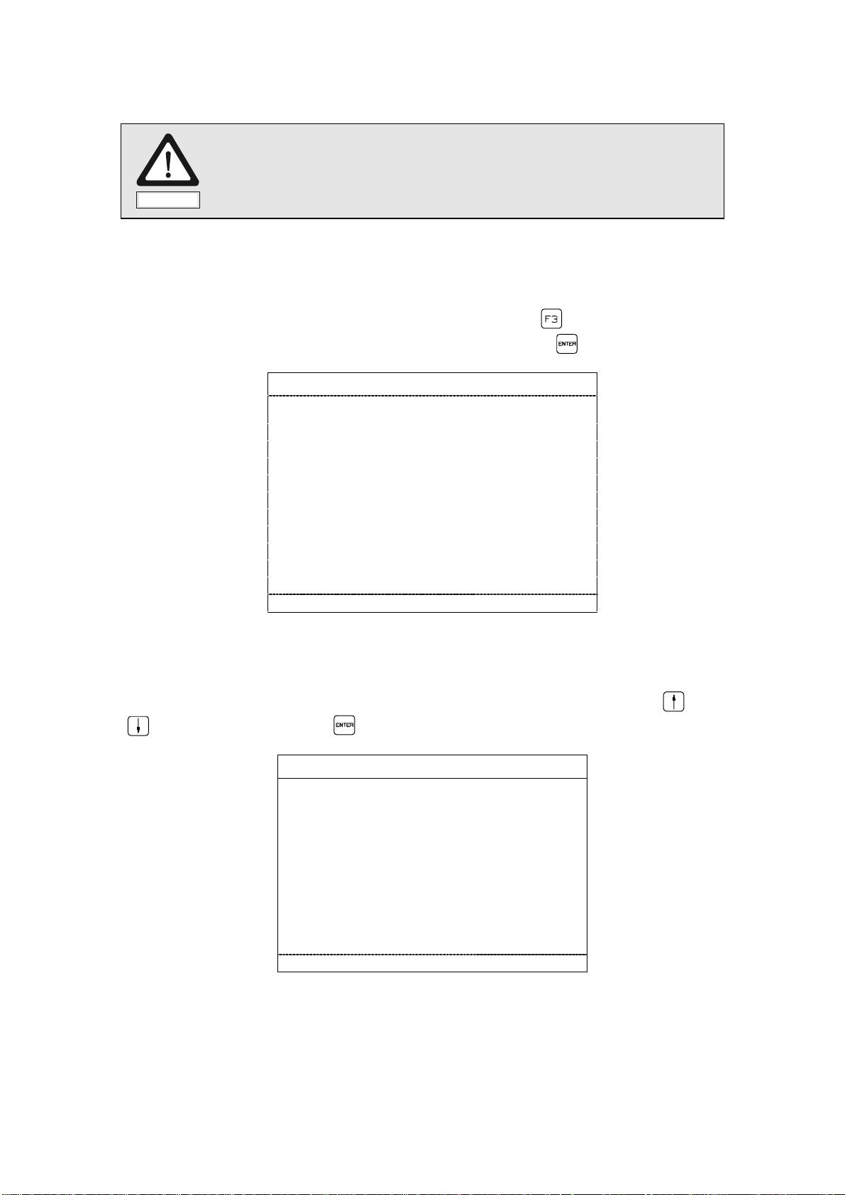
1.5 Sub-M e nu "Clear Fault Condition"
The sub-menu "Clear Fault Condition" can be selected directly with the function
key or by positioning the cursor on the fourth line of the main menu
"OPERATION" and then pressing .
In case of no fault condition the following will be displayed on the monitor when the
sub-menu "Clear Fault Condition" is selected:
OPERATION
Weld parameter monitoring
Programming
Statistics
Fault reset
No fault exist
Status TMP
Functions
Warnings
<↓↑> <ENTER> <F1..F5>
In case of a TMP system fault all fault sources will be displayed
Fault condition
To continue operation clear
the fault condition.
<F1..F5> <ESC>
If system faults requires the opening of the weld unit it is exclusively
reserved for authorized and qualified personnel. All fault messages
will be cleared when the TMP unit is switched on again, following
the remedy of the fault condition.
17
Artisan Technology Group - Quality Instrumentation ... Guaranteed | (888) 88-SOURCE | www.artisantg.com
Page 21

In case there are simultaneous faults at other TMP outputs apart from the unit
faults (flashing of one, of several or of all "operation/error"-LED‘s) these can be
represented as follows after the system fault has been remedied.
Fault output #
<RESTART> <SET WC> <STUD>
<←↓↑→> <ENTER> <F1..F5> <ESC>
Select output and program number and confirm with . The individual menu lines
of the display signify the following:
Fault Output # The fault is only related to the TMP output displayed. All faults
of this output will be listed.
The fault occurred will cause a defective weld cycle.
In case there are simultaneous faults at other TMP outputs these can be
represented alternately with the direction keys and .
The sub-menu "Clear Fault Conditio n" offers the user several possibilities how to
deal with fault messages
The below mentioned operations can be selected with the two cursor keys ,
and activated by pressing the key.
RESTART By selecting RESTART the fault will be reset and the weld will
be performed if there is a start weld signal, if possible.
SET WC With the command SET WC the fault will be reset, if possible
and the signal "Welding complete" will be issued.
STUD With the command STUD a stud feeding cycle will be initiated,
if possible.The screen display remains the same; the fault
message will not be reset.
Remark: In case the fault message will not reset after having performed the
corresponding operation the f ollowing message will be displayed:
"Function cannot be performed"
18
Artisan Technology Group - Quality Instrumentation ... Guaranteed | (888) 88-SOURCE | www.artisantg.com
Page 22

Please note the remedial measures in the corresponding operating manuals for
the reseting of faults at unit peripherals.
Having reset the fault the menu selected before the fault occurred will be redisplayed automatically.
Irrespective of the removal of faults you can exit the sub-menu "Fault Reset" by
pressing and return to the main menu.
Remark: If the fault can not be cleared by either RESET, RESTART or SET WC
reseting of faults is limited to the remedial measures listed in section "Fault
Messages".
Operational defects of the weld equipment which can not be
cleared through the listed remedial measures are to be fixed by
qualified service personnel.
19
Artisan Technology Group - Quality Instrumentation ... Guaranteed | (888) 88-SOURCE | www.artisantg.com
Page 23
1.6 Sub-Menu "Status Weld Sequence"
The sub-menu "Status Weld Sequence" is to be selected for obtaining an overview on the weld circuit-related signals. Position the cursor on the corresponding
menu line of the main menu and press the key.
Status weld sequence
12345
Weld cycle # # # # #
Feed cycle # # # # #
SOW # # # # #
Angularity switch PK # # # # #
Start weld # # # # #
Start feed # # # # #
SKK R-position # # # # #
I. Tolerance # # # # #
Program number ### ### ### ### ###
<F1..F5> <ESC>
The individual menu lines of the dispay signify the following:
The status information is related to output 1 ... 5 of the TMP-weld unit.
Weld cycle *: Weld cycle operation.
-: No weld cycle operation.
Feed cycle *: Stud feeding operation.
-: No stud feeding operation.
SOW *: SOW (stud on workpiece) signal is active.
-: No SOW signal.
Angularity
switch PK
*: Angultary signal is active.
-: No angultary signal.
Start weld *: Start weld signal is active.
-: No start weld signal.
Start feed *: Start feed signal is active.
-: No start feed signal.
20
Artisan Technology Group - Quality Instrumentation ... Guaranteed | (888) 88-SOURCE | www.artisantg.com
Page 24

SKK R-position *: SKK retracted signal is active.
-: No SKK retracted signal
I/O Tolerance *: Parameters are within the operating tolerance range.
-: Parameters are out of operating tolerance range
Program
number
1-127 : Display of program no under which the last weld was
performed.
By pressing or you will return to the main menu.
21
Artisan Technology Group - Quality Instrumentation ... Guaranteed | (888) 88-SOURCE | www.artisantg.com
Page 25

1.7 Sub-menu "Status Customer Interface"
The sub-menu "Status Customer Interface" is to be selected for obtaining an
overview on interface signals given. Position the cursor on the sixth menu line of
the main menu and press the key.
Status customer interface
#####
Operation mode #### #### #### #### ####
Start weld #####
Start feed #####
Without weld #####
Reset fault #####
Restart #####
Set WC #####
Start SKK F-pos. #####
Start SKK R-pos. #####
Program number ### ### ### ### ###
<F1..F5> <ESC>
The individual menu lines of the display signify the following:
Status information is related to output 1 ... 5 of the TMP - weld unit.
AUT Selected operation mode: "automatic".
MAN Selected operation mode: " man ual " .
STOP Selected operation mode: "operati on stop ".
The following menu lines represent through “ * “ whether a signal has been given
or through“ - “ that a signal has not been given.
Start Weld *: The signal "start weld " is set via the interface.
-: The "start weld" signal has not been set
Start Feed *: The signal "start feed" is given via the interface.
-: The signal "start feed" has not been set
Without weld *: The signal "without weld" has been set.
-: The signal "without weld" has not been set
Reset fault *: The signal “reset fault“ is set.
-: The signal “reset fault“ has not been set.
22
Artisan Technology Group - Quality Instrumentation ... Guaranteed | (888) 88-SOURCE | www.artisantg.com
Page 26

Restart *: The signal "restart" has been set.
-: The signal "restart" has not been set
Set WC *: The signal “Weld complete“ is set.
-: The signal “Weld complete“ has not been set.
Start SKK F-pos. *: The signal for advancing the weld head slide rail is set.
-: The signal "start SKK extend" has not been set
Start SKK R-pos. *: The signal for retracting the weld head slide rail is set.
-: The signal “start SKK retract“ has not been set.
Program number
1...127: Number of the weld program selected via the
customer interface.
Remark: If a signal is set the corresponding command is given via the customer
interface.
By pressing or you will return to the main menu.
23
Artisan Technology Group - Quality Instrumentation ... Guaranteed | (888) 88-SOURCE | www.artisantg.com
Page 27

1.8 Sub-menu "Status Feeder / Stud Divider"
The sub-menu "Status Feeder / Stud divider" is to be selected for obtaining an
overview on the feeder and stud divider signals. Position the cursor on the seventh
menu line of the main menu and press the key.
Status feeder / stud divider
#####
Operation mode ### ### ### ### ###
Feed cycle #####
Piston retracted #####
Pos. Stud divider #####
SKK R-position #####
Angularity switch PK #####
Start weld #####
Start feed #####
Stud level low #####
<F1..F5> <ESC>
The individual menu lines of the display signify the following:
Status information is related to output 1 ... 5 of the TMP - weld unit.
Operation Mode
Feeder is in operation mode "Automatic","Manual" or "Test".
Feed cycle *: Display that a feeding cycle is performed.
-: No feeding cycle performed.
Piston retracted *: SKK/PK piston is retr acted.
-: Piston is not retracted.
Position Stud Div. *: Display of current stud divider position.
-: No stud divider position recognized.
SKK retracted *: SKK is retracte d.
-: No input signal “SKK retracted“.
Angularity switch
PK
*: Angultary signal is active.
-: No angultary signal.
Start weld *: Start weld signal is active.
-: No start weld signal.
Start feed *: Start feed signal is active.
-: No start feed signal.
Stud level low *: Stud level low signal is active.
-: No stud level low signal.
By pressing or you will return to the main menu.
24
Artisan Technology Group - Quality Instrumentation ... Guaranteed | (888) 88-SOURCE | www.artisantg.com
Page 28

1.9 Sub-menu "Status TMP . . . . "
This sub-menu contains specific messages and information on the peripheral
units. Position the cursor on the eighth menu line of the main menu and press the
key.
Status TMP
Date. . . . . . . . . . . ##.##.## Time . . . . . . . ##.##.##
Software. . . . . . . V##.## Address. . . . . . . . . ###
Interface. ########### SMPS ready. . . . . ####
Operation stop. . . . #### Emergency . . . . . . ####
#####
Connection ##### ##### ##### ##### #####
SF-Typ #### #### #### #### ####
SKK/PK ### ### ### ### ###
SF..A/D # # # #
Lift sensor #### #### #### #### ####
Maintenance # # # #
<F1..F5> <ESC>
By pressing or you will return to the main menu.
The individual menu lines of the display signify the following:
Date Shows the date in the sequence of "day.month.year".
Time Shows the time in the sequence of "hour:minutes:seconds".
Software
The version no. (V ##.##) informs about the present software
version of the TMP weld unit.
Address When connecting several TMP weld units to a central personal
computer each TMP must be attributed a custom er - speci fic addr ess
Interface The following customer interface are possible: parallel, Interbus-S,
Profibus DP or no interface.
SMPS ready The weld energy source SMPS is ready / not ready
Stop
Display of existing / not existing stop operation
Operation
Emergency Display of existing / not existing emergency stop
Connection norm: standard feeder configurated
SD2-M master feeder SD2 configurated
SD2-S: slave feeder SD2 configurated
SD5-Z: SD5 feeder configurated
SD5-W: SD5 divider configurated
PKE: manual gun extension configurated
25
Artisan Technology Group - Quality Instrumentation ... Guaranteed | (888) 88-SOURCE | www.artisantg.com
Page 29

SF-Typ Represents the connected feeder type, i.e. SF 12, SF 50, SF 52,
SF 53, SF 54, SF 56. If no feeder is connected,“ - “ is displayed.
SKK/PK If a weld head is connected, SKK is displayed, otherwise PK or
“ - “ is displayed.
SF..A/D If the feeder is equipped for slide rail control, “ D “ is displayed,
otherwise “ A “ or “ - “ is displayed.
Lift sensor If the weld head is equipped for lift measuring, “ yes “ is displayed,
otherwise “ no “ or “ - “ is displayed.
Maintenance If the weld tool exceeded the programmed limit value, “ ! “ is
displayed, otherwise “ - “ is displayed.
26
Artisan Technology Group - Quality Instrumentation ... Guaranteed | (888) 88-SOURCE | www.artisantg.com
Page 30

1.10 Sub-menu "Functions"
This sub-menu contains a command mode for the manual control of the TMP as
well as the possibility to display the software levels.
The sub-menu "Functions" will be opened by positioning the cursor on the last
menu line of the main menu and by pressing the key.
The individual functions are to be selected via the keys , and .
.Functions
display system configuration
test mode cycle functions
test mode outputs interface
test mode weld process
test mode power supply
<↓↑> <ENTER> <F1..F5> <ESC>
By pressing or you will return to the main menu.
1.10.1 Function Menu "Displa y System Configuration"
This sub-menu will be selected b y positioning the cursor on the first menu line of
the sub- menu "Functions" and by pressing the key.
E M H A R T T M P ####
System software V ##.##
Keypad/Display V ##.##
Central CPU V ##.##
SMPS V ##.##
Interface ########### V ##.##
Outlet 1 #### / #### V ##.##
Outlet 2 #### / #### V ##.##
Outlet 3 #### / #### V ##.##
Outlet 4 #### / #### V ##.##
Outlet 5 #### / #### V ##.##
<F1..F5> <ESC>
The TMP will identify itself by displaying unit and peripherals as well as the
corresponding software versions.
By pressing you will return to the sub-menu "Functions".
27
Artisan Technology Group - Quality Instrumentation ... Guaranteed | (888) 88-SOURCE | www.artisantg.com
Page 31

1.10.2 Function Menu "Test Mode Cycle Functions"
In test mode important control commands can be given directly at the control
panel. These control commands supersede external customer control and will be
executed immediately.
This sub-menu will be selected by positioning the cursor on the second menu line
of the sub- menu "Functions" and by pressing the key
Test mode cycle functions
12345
Cyclus ##### ##### ##### ##### #####
SKK F-pos. ##### ##### ##### ##### #####
SKK R-pos. ##### ##### ##### ##### #####
Start feed ##### ##### ##### ##### #####
Lift ##### ##### ##### ##### #####
Set WC ##### ##### ##### ##### #####
Color mark ##### ##### ##### ##### #####
Reference outlet : #
SKK ext. . . #### ms Drop time. . . ##, # ms
SKK ret. . . #### ms Lift. . . . . . . . #, ## ms
<←↓↑→> <ENTER>=Start <F1..F5> <ESC>
To execute a certain function the corresponding menu line as well as the TMP
output number is to be selected with the cursor keys. The start command will be
given by operating the key.
Remark: Test mode will be automatically cancelled if no key is operated within 60s.
- As a precaution additionally the “ “ - key must be pressed.
Attention: With certain software levels (f.i. System V1.30, OPEL carline) these
test functions may still be performed despite the system bein g in stop
operation mode.
The individual menu lines of the display signify the following:
Cycle The command for executing a weld sequence test without
performing an actual weld can be given.
SKK ext. The command for advancing the weld head can be given.
SKK ret. The command for retracting the weld head can be given.
Start feed The command for “stud feeding“ can be given.
Lift The command for executing a lift can be given.
28
Artisan Technology Group - Quality Instrumentation ... Guaranteed | (888) 88-SOURCE | www.artisantg.com
Page 32

Set WC A WC-signal is generated for the selected output
Color mark A color mark is generated for the selected output
The readings of the selected TMP output will be displayed in menu lines 10
and 11. If the connected SKK is equipped with a lift measuring system
(option) the measured lift will be displayed in menu line 11.
By pressing you will exit the "test mode cycle functions". By pressing you
will return to the main menu.
29
Artisan Technology Group - Quality Instrumentation ... Guaranteed | (888) 88-SOURCE | www.artisantg.com
Page 33

1.10.3 Function Menu "Test Mode Outputs Interface"
2 3 4 5
# # # #
# # # #
# # # #
# # # #
# # # #
# # # #
# # # #
# # # #
In the function menu "Test Mode Outputs Interface" the customer interface
signals may be set and tested.
This sub-menu will be selected by position ing the cursor on the third menu line
of the sub- menu "Functions" and by pressing the key.
Test mode outputs interface
1
Operation mode #### #### #### #### ####
Ready #
SOW #
SKK R-position #
I.Tolerance #
Fault #
WC #
Maintenance #
Emergency stop #
Fault code ### ### ### ### ###
<←↓↑→> <ENTER>=Start <F1..F5> <ESC>
The cursor can be moved within the table with the direction keys. Signals will be
set or cancelled by pressing or .
The individual menu lines of the dispay signify the following:
Operation
mode
The following operation modes can be simulated: AUTO, TEST,
PROG, ERR, STOP, NO
Outputs The following outputs can be connected: ready, SOW, SKK back,
i. tolerance, fault, WC, maintenance, emergency stop.
Fault code An fault code no. from 1 - 255 can be set.
The test mode can only be performed if the signal for stop
operation has been set by customer control.
By pressing you will exit the "Test Mode Outputs Interface" mode. By pressing you will return immediately to the main menu.
30
Artisan Technology Group - Quality Instrumentation ... Guaranteed | (888) 88-SOURCE | www.artisantg.com
Page 34

1.10.4 Function Menu "Test Mode Weld Process"
During test mode all signals at the customer interface will be processed as in
standard operation. Control commands will be executed without the weld cur-rent
being enabled.
This function will be selected by position ing the cursor on the fourth menu line of
the sub- menu "Functions" and by pressing the key.
Test mode weld process
1234 5
Weld cycle # # # # #
Feed cycle # # # # #
SOW # # # # #
Angularity switch PK # # # # #
Start weld # # # # #
Start feed # # # # #
SKK R-position # # # # #
I.Tolerance # # # # #
Program number ### ### ### ### ###
Warning ! The TMP-unit will work in test mode
However the unit will not weld !
<F1..F5> <ESC>
Regarding the function, this menu isidentical with the menu “Status Weld
Process“. It displays various process data.
The test mode can only be performed if the signal for “Without
welding“ has been set by customer control.
By pressing or you will return to the main menu.
31
Artisan Technology Group - Quality Instrumentation ... Guaranteed | (888) 88-SOURCE | www.artisantg.com
Page 35

1.10.5 Functions Menu “Test Mode Power Supply“
In the Function Menu "Test Mode Power Supply" the function of the SMPS can be
tested in a short circuit
• Select the requested function menu with the direction keys and .
• Confirm your entry with .
Test mode power supply
Output No. . . . . . . . . . . : #
Quantity of testcycles. : ###
Start . . . . . . . . . . . . . . . : #####
Actual weld current . . . . : #### A
Actual cycle count. . . . . : ###
The short circuit test can be stopped
with the <ESC> key
<←↓↑→> <+, -> <ENTER> <F1..F5> <ESC>
• Select the output that is to be tested.
• Position the cursor on the menu line "Start".
• Confirm your entry with .
• Press to start the test cycle.
Remark: Test mode will be automatically cancelled if no key is operated within 60 s.
• Press and simultaneously to start the function.
Remark: With some software versions it is possible to execute these test functions
even with an active Operation stop.
The individual menu lines of the display signify the following:
Output nr. Select the output for which the test mode is to be executed
Number of cycles
Number of test cycles that are to be simulated.
(ref)
Start Press the keys and simultaneously to start the
function
32
Artisan Technology Group - Quality Instrumentation ... Guaranteed | (888) 88-SOURCE | www.artisantg.com
Page 36

Weld current act The measured weld current
Number of cycles
Number of test cycles executed
(act.)
• By pressing you will return to the function menu.
• By pressing you will return to the main menu.
33
Artisan Technology Group - Quality Instrumentation ... Guaranteed | (888) 88-SOURCE | www.artisantg.com
Page 37

1.11 Function Menu "Warnings"
The sub-menu “Warnings“ can be accessed by positioning the cursor on the tenth
line of the main menu “OPERATION“ and by pressing the key
If there is no warning message available when selecting the sub-menu “Warnings “
the following screen message will be displayed:
OPERATION
Weld parameter monitor
Programming
Statistics
Fault reset
No warning message available
Status TMP
Functions
Warnings
<↓↑> <ENTER> <F1..F5>
Warnings will be marked by “ slow “ flashing of the corresponding output LED. If
there are warnings available they will be displayed in the sub-menu “Warnings“.
Warnings
<F1..F5> <ESC>
The following warnings can be displayed:
Maintenance
The number of welds exceeds the set limit value
clamping tongs
Maintenance weld
head
The gun drop time established via 10 welds exceeds
the programmed limit values (the differences to the
programmed drop time are evaluated).
Level to low The proximity switch for monitoring the filling level in the
stud feeder is not covered.
C-CPU: empty
battery RAM-module
The battery in the RAM-module on the central CPU is
run down. Before replacing the RAM-module a backup
via PC should be performed.
C-CPU: empty
battery clock
Artisan Technology Group - Quality Instrumentation ... Guaranteed | (888) 88-SOURCE | www.artisantg.com
The battery for securing the real-time clock is run down
and must be replaced.
34
Page 38

1.12 Sub-Menu "Extended Functions"
Access to the sub-menu "Extended Functions" is secured by a
code and is exclusively reserved for the service personnel.
Extended functions
System parameters
Mechanical parameters
Weld parameters
Copy programs
Clear functions
ZCPU system test
De / activate programs
Stud length detection
Set date and time
<↓↑> <ENTER> <F1..F5> <ESC>
This menu gives access to all data which are related to the weld process.
The menu “Extended Functions“ can be accessed via the sub-menu “Program-
ming“ by pressing first the < + > key and then the < 0 > key.
There is also the possibility to access the individual sub-menues directly through
the following codes.
<+> <1> : System parameters
<+> <2> : Mechanical parameters
<+> <3> : Weld parameters
<-> <99> : Clear functions
35
Artisan Technology Group - Quality Instrumentation ... Guaranteed | (888) 88-SOURCE | www.artisantg.com
Page 39

1.12.1 Function Menu "System Parameters"
This function menu will be selected by positioning the cursor on the first menu line
of the "Extended Functions" menu and by pressing the key.
TMP version1 TMP version 2
System parameters
Address Interface . . . . . ###
Network . . . . . .###
Language . . . . . . ###########
Parameter printout: . . . . . #######
###########
#############
##########
<↓↑> <+, -> <ENTER> <F1..F5> <ESC>
System parameters
Address Interface . . . . . . ###
Network . . . . . . .###
Language . . . . . . . . . . . . . .###########
<↓↑> <+, -> <ENTER> <F1..F5> <ESC>
Address Interface The unit address Interface serves to identify the TMP
when connecting it to the Pro-Bus customer interface.
Address Network The unit address Network serves to identify the TMP
when connecting several weld units to a central PC.
Select a number between 1 and 255 to identify the unit.
Language
There are two country-specific languages available to the
user for the communication between the TMP weld unit
and the operating personnel.
Parameter printout
The printer output can be activated and adapted here
- Printing of WOP or WIP and WOP
- Individual or all weld outputs
- Bautrate
36
Artisan Technology Group - Quality Instrumentation ... Guaranteed | (888) 88-SOURCE | www.artisantg.com
Page 40

1.12.2 Function Menu "Mechanical Par ameters"
This function menu will be selected by positioning the cursor on the second menu
line of the "Extended Functions" menu and by pressing the key.
Mechanical parameters outlet : #
Outlet active . . . .####
Slide rail . . . . ######
Start feed . . . . ##################
Feedtime . . . . . . ####
Loadtime . . . . . ####
Repeat feed . . . .#### Feed adj . . . . . . ####
Permitted WOP . # Color mark . . . . . ####
Protect. gas . . . .#### Air blow . . . . . . . ####
Pre-gas (ms) . . . #### Angularity . . . . . . ####
Post-gas (ms) . . #### Stud monitor. . . . ####
Maint. at . . . . ###### tp-Maint . . . . . . + # - #
Fault at . . . . ###### tp-Fault . . . . . . + # - #
<1..5> <←↓↑→> <+,-> <ENT> <F1..F5> <ESC>
When the menu "mechanical parameters" has been opened the cursor will move
into the heading requesting the input of the selected SKK/PK outlet no. (1 - 5).
SKK/PK: No. in
standard
operation
SKK/PK: No in
operation with SD2
In standard operation (feeder - SKK/PK) the SKK/PK no. is to be
entered according to the TMP configuration. For example: "TMP
output 1 - feeder 1 - SKK/PK No. 1".
For programming the weld head parameters as well as for
programming the parameters of t he "master" f eeder select o nly the
SKK/PK output no. 1.
Information: In order to program the feeding time of the second
stud feeder select SKK/PK output no. 2 while the menu line
"SKK/PK active" displays "yes".
SKK/PK: No. in
operation with
SD5
When operating with a 5-way stud divider the SKK no. must be
entered as it is at the "SD5-stud divider".
For example: "SD5-output 3 - SKK No. 3".
Enter the respective SKK/PK output no. with the numerical keys and confirm with
The cursor is now positioned in the first menu line requesting input. With the
direction keys you can access the various menu lines directly.
The individual menu lines of the display signify the following:
SKK/PK active
Slide rail
Artisan Technology Group - Quality Instrumentation ... Guaranteed | (888) 88-SOURCE | www.artisantg.com
Yes : The output of the TMP-weld unit is activated.
No : The output of the TMP-weld unit is not activated.
Internal: The SKK slide rail will be controlled by the TMP-weld unit.
External: The SKK slide rail will be under customer-specified control.
37
Page 41

Start feed
Extern after SOW: The customer may execute a start signal for
"stud feeding" after the collet has diseng ag ed from the w elded
stud.
Intern after SOW: The TMP weld unit will execute the "stud feeding"
cycle after the collet has disengaged from the welded stud.
Extern after WC: The customer may execute a start signal for
"stud feeding" after the end of each welding process.
Internal after WC: The TMP weld unit will execute the "stud feeding"
cycle after the end of each welding process.
Feedtime
Loadtime
Repeat
feed
Feed
adjustment
The time between executing the stud feeding signal and arrival of
the stud in the receiver can be adjusted in a range from of 50 ms 1600 ms.
T-Studs SWB 10 with SF 54: The time between piston retract
signal and the end of feedtime can be adjusted in a range from
50 ms - 1600 ms.
Other Studs with SF ..: The time between piston retract signal and
enabling of the blow air can be adjusted in a range from
50 ms - 1600 ms.
Yes: If the SOW signal is not recognized when the weld tool
moves forward the feeding process will be repeated.
No:
No auto-refeed requested.
Yes: The feeding cycle is terminated upon arrival of the stud in
the weld tool disregarding the feeding time.
(Condition: SKK/PK is equipped with a sensor for weld stud
detection).
No automatic feed adjustment.
No:
Permitted
WOP
Sequential welds out of tolerance can be limited by the customer
by selecting a number between 1 - 9. When this number has been
reached the welding operation will be interrupted.
Color mark Yes: When connecting color marking units SMB 128 (option) welds
out of tolerance will be marked by color.
No: Welds out of toleran c e will not be marked by color.
Protec. gas
Yes: Shielded arc welding operation with gas ( opti on) is activated
No: Shielded arc welding operation with gas is not activated.
38
Artisan Technology Group - Quality Instrumentation ... Guaranteed | (888) 88-SOURCE | www.artisantg.com
Page 42

Air blow Yes: If the weld tool is optionally equipped with an air nozzle
for clearing the work surface, it will be activated
No: Air nozzle for clearing the work surface will not be activated.
Pre-gas The time of protect. gas flow before weld begin can be adjusted
in a range from 0 ms - 1000 ms.
Post-gas
The time of protect. gas flow after the weld has been performed
can be adjusted in a range from 0 ms - 1000 ms.
Angularity
switch
Yes : n.c.
No : n.c.
Stud monitor Yes: Stud length detection will be activated.
Special case SD2: Additionally testing of the feeder
allocated by the programm is activated.
No: Stud length detection will not be activated.
Maint. at 0...950.000 : Number of welds with a collet after which the
maintenance warning will be activated (step size: 5000).
" 0 " selections will not be monitored.
tp-Maint. 0 - ±8 : Tolerance value for testing the drop time. If it is exceeded
the maintenance warning will be a c tivated.
" 0 " selections will not be monitored.
Fault at 0...950.000 :. Number of welds with a collet after which the output
will be set into fault condition (step size: 5000).
“ 0 “ selections will not be monitored.
tp-Fault 0 - ± 8 : Tolerance value for testing the drop time. If it is exceeded
the output will be set into fault condition.
“ 0 “.selections will not be monitored.
Remark: Programming is to be effected via the and keys
Programmed parameters will be confirmed with or rejected with . You may
exit the input mode by pressing the key.
39
Artisan Technology Group - Quality Instrumentation ... Guaranteed | (888) 88-SOURCE | www.artisantg.com
Page 43

1.12.3 Function Menu "Weld Program"
This function menu will be selected by positioning the cursor on the third menu line
of the "Extended Functions" menu and by pressing the key.
This menu consists of two monitor pages. You can alternately display them by
pressing the keys and in the corresponding menu line.
Outlet: # Weld program: ###
Program active . . . . . . ####
Pilot current . . . . . . . .. ## A
Pilot current time. . . . . ## ms
Weld current . . . . . . . #### + ### - ### A
Weld current time . . . . ### + ## - ## ms
Varc pilot current. . . . . ## + ## - ## V
Varc weld current . . . . ## + ## - ## V
Optimization. . . . . . . . ####
Weld type . . . . . . . . . . ###########
Program continues <##>
<1..5> <←↓↑→> <+,-> <ENT> <F1..F5> <ESC>
When the menu "Weld Program" has been opened the cursor will move into the
heading requesting the input of the selected outlet no. (1 - 5).
Enter the outlet no. as well as the number of the weld program with the numerical
keys and confirm each with .
Now the cursor is positioned in the first menu line. You can access the various
menu lines with the direction keys and directly.
Program active Yes : External program selection enabled
No : External Program selection disabled.
Remark: if no external program selection is requested only weld
program 1 may be activated for the corresponding output.
Pilot current Selection of pilot current in a range from 20A - 30A.
Pilot current time
Weld current Selection of weld current in a range from 100A - 1000A.*
+ tolerance
- tolerance
Selection of pilot current time 30 ms - 60 ms.
Positive tolerance from 0 - 100A (Selection of “0“ will cancel monitoring)
Negative tolerance from 0 - 100A (Selection of “0“ will cancel monitoring)
* depending on the unit type!
Weld current time Selection of weld time in a range from 6 ms - 1000 ms.
+ tolerance
Positive tolerance from 0 - 8 ms (Selection of “0“ will cancel
monitoring)
- tolerance
Artisan Technology Group - Quality Instrumentation ... Guaranteed | (888) 88-SOURCE | www.artisantg.com
Negative tolerance from 0 - 8 ms (Selection of “0“ will cancel monitoring)
40
Page 44

Varc pilot current Input of arc voltage value (pilot current phase) for parameter monitoring
(range: 16V - 36V).
+ tolerance Positive tolerance from 0V-10V (Selection of “0“ will cancel monitoring)
- tolerance Negative tolerance from 0V-10V (Selection of “0“ will cancel monitoring)
Varc weld current Input of arc voltage value (in main current phase) in a range from
16V - 36V.
+ tolerance Positive tolerance from 0V–10V (Selection of “0“ will cancel monitoring)
- tolerance Negative tolerance from 0V–10V (Selection of “0“ will cancel monitoring)
Optimization No : Optimization of weld parameters not requested.
Current : Automatic adjustment of the weld current when welding
through impurities on work surfaces.
Time : Aut omatic adjustment of the weld time ts when welding
through impurities on work surfaces.
Weld type DC : Welding with constant current
Pulse : Welding with pulse wave form current
Remark: Programming is to be performed with the keys and .
Program
continues
The second menu page can be displayed by pressing the
direction key .
Having pressed the key the cursor will have moved to the second menu page.
Outlet : # Weld program: ###
Program continues . . . < ↑ >
Start delay . . . . . . . . . ### ms
Lift distance . . . . . . . . # ,## +, ## -, ## mm
Drop time . . . . . . . . . . ## ms
Autoplunge . . . . . . . . . ####
Air blow . . . . . . . . . . . ####
Detect stud . . . . . . . . . ####
Corresponding stud . . #########
Weld part ident. . . . . . ################
<1..5> <←↓↑→> <+,-> <ENT> F1..F5> <ESC>
Program continues The first menu page can be displayed by pressing the direction key
Start Delay If the weld location is not sufficiently stable the time between SOW and
lift can be adjusted in a range between 0 ms - 500 ms.
41
Artisan Technology Group - Quality Instrumentation ... Guaranteed | (888) 88-SOURCE | www.artisantg.com
Page 45

Lift distance
+ tolerance
- tolerance
Drop time Input of the time between de-energizing of the solenoid and the plunging
Autoplunge Yes : Autoplunge is activated to keep weld time constant.
Input of lift value in a range from 0,6mm-3,0mm for parameter monitoring
(step size: 0,1 mm).
Note: Input only necessary when the connected weld tool is equipped with an
integrated lift measurement system to detect distance.
Positive tolerance from 0-0,6mm (Selection of “0“ will cancel monitoring)
Negative tolerance from 0-0,6mm (Selection of “0“ will cancel monitoring)
of the stud into the melted work surface.
Note: Input serves to adapt weld time to stud plunge time and also
serves as reference value for maintenance monitoring
No : No autoplunge requested.
Air blow Yes: If the weld tool is optionally equipped with an air nozzle
for clearing the work surface, it will be activated
No:
Air nozzle for clearing the work surface will not be activated.
Detect stud
Yes : Stud detection via the length measurement function of the lift
measuring system is activated.
No : No autoplunge requested
Attention: Stud detection function is only performed if the stud detection
function in the mechanical parameters has been activated as well.
Remark: If "Detect Stud" is activated it will be verified before each weld whether the
stud length of the supplied stud is according to the programmed reference value. In
case of an deviation the corresponding fault message will be initiated.
Corresponding
stud
Feeder 1 - 5 : The weld program will be attributed a feeder.
Note: It will be verfied before the weld whether the last stud feed was
performed by the correct feeder.
None : Corresponding stud verification feature not requested
Remark: Verification of corresponding stud is only possi ble dur i ng operati on wi th a 2way stud divider SD 2.
Weld part
identification
Input of an alpanumeric text for identification of the weld part
Remark: Programming is to be effected via the , , and keys.
Programmed parameters will be confirm ed with or rejected with . You may
exit the input mode by pressing the key.
42
Artisan Technology Group - Quality Instrumentation ... Guaranteed | (888) 88-SOURCE | www.artisantg.com
Page 46

1.12.4 Function Menu "Copy Programs"
The function menu "Copy Programs" serves to transfer weld programs.
This function menu will be selected by positioning the cursor on the fourth menu
line of the "Extended Functions" menu and by pressing the key.
Copy programs
Single program
Program area
Programs per output
Copy Outlet # ####### ###
To Outlet # ####### ###
#### ####### ###
<1..9> <↓↑> <ENTER> <F1..F5> <ESC>
The user has the following possibilities to copy weld programs:
Single Program In selecting "Single Program" one copy of the weld program will
be made
Program Area In selecting "Program Area" several copies of the weld program
will be made
Programs per
Output
In selecting "Programs per Output" allweld programs of an
output will be copied
Select the requested copy function with the direction keys and and confirm
with .
Select a number between 1 and 5 for the weld output as well as a number
between 1 and 127 for the weld program and confirm your input with .
By pressing the cursor will move to the function selection and by pressing
again you will exit the menu.
Information on copying programs:
Weld programs will need to be copied when in a robot unit studs are to be welded
at different weld locations with identical programs. The stud detection is not
copied.
If a weld program is copied to an address under which a program is
already stored the existing program will be overwritten by the new
program.
43
Artisan Technology Group - Quality Instrumentation ... Guaranteed | (888) 88-SOURCE | www.artisantg.com
Page 47

1.12.5 Function Menu "Clear Functions"
The function menu "Clear Functions" serves to Clear and thus to reset counters
and memories of the statistics menu.
This function menu will be selected by positioning the cursor on the fifth me nu line
of the "Extended Functions" menu and by pressing the key.
Clear functions
1 2 3 4 5
Maintenance ####################
Statistic ####################
Fault memory ########################
WOP memory ########################
<←↓↑→> <ENTER>=Clear <F1..F5> <ESC>
The individual menu lines signify the following:
Maintenance
By clearing "Maintenance" the statistics in "Maintenance"
menu information will be reset to "0" . Any existing
maintenance warning will be automatically reset
Statistic
By clearing the "Statistics" the information in the two statistics
menus "Weld Output" and "Weld Program Statistics" will be
reset to "0"
Fault Memory
By clearing the "Fault Memory" all information will be deleted
in the "Fault Memory"
WOP Memory
By clearing the "WOP Memory" all information will be deleted
in the "WOP Memory"
For selecting statistics or a memory position the cursor with the direction keys
And and confirm with the key. The message "Activate Clear Function"
will appear on the display.
By pressing the key the selected memory will be cleared, by pressing the
selection will be cancelled. By pressing again you will exit the menu "Clear
Functions".
44
Artisan Technology Group - Quality Instrumentation ... Guaranteed | (888) 88-SOURCE | www.artisantg.com
Page 48

1.12.6 Function Menu "ZCPU S ystem Test"
This function menu will be selected by positioning the cursor on the sixth menu
line of the "Extended Functions" menu and by pressing the key.
ZCPU System test
RAM-Module:
- existent . . . . . . . . . . . . . . . . . . . . . . #
RAM-Module Battery:
- within operating tolerance. . . . . . . . #
- voltage level (Volts) . . . . . . . . . . .#, #
ZCPU Battery:
- within operating tolerance. . . . . . . . #
- voltage level (Volts) . . . . . . . . . . .#, #
<F1..F5> <ESC>
The individual menu lines will be described on the following pages:
RAM-Module : The system test checks whether the RAM-module is responsive.
Existent * :
A RAM-Module is existent.
No RAM-Module.
- :
RAM-Module battery : The system checks the battery in the RAM-Module
Tolerance * : The battery voltage is within the operating tolerance.
The battery voltage is out of the operating tolerance
- :
Voltage level The system test will indicate the measured battery voltage
ZCPU-Module battery : The system checks the battery on the ZCPU (real-time
clock)
Tolerance * : The battery voltage is within the operating tolerance.
- : The battery voltage is out of the operating tolerance
Voltage level The system test will indicate the measured battery voltage
By pressing the key you will exit the function menu "ZCPU System Test“.
45
Artisan Technology Group - Quality Instrumentation ... Guaranteed | (888) 88-SOURCE | www.artisantg.com
Page 49

1.12.7 Function Menu "De/Activate Program"
The function menu “De/Activate Program“ displays a clearly arranged overview on
the active/inactive weld programs in terms of output. Individual programs may be
de/activated.
The function menu is selected by positioning the cursor on the seventh line of the
“Extended Functions“ menu and then pressing the key.
Overview active programs O: #
12345678910
11 12 13 14 15 16 17 18 19 20
21 22 23 24 25 26 27 28 29 30
31 32 33 34 35 36 37 38 39 40
41 42 43 44 45 46 47 48 49 50
51 52 53 54 55 56 57 58 59 60
61 62 63 64 65 66 67 68 69 70
71 72 73 74 75 76 77 78 79 80
81 82 83 84 85 86 87 88 89 90
91 92 93 94 95 96 97 98 99 100
101 102 103 104 105 106 107 108 109 110
111 112 113 114 115 116 117 118 119 120
121 122 123 124 125 126 127
<1..5> <←↓↑→> < + >=active < - >=inactive <ESC>
An overview on all programs nos. is displayed. Program numbers displayed in
italic are activated.
In order to alter a de/activation the cursor must be positioned on the requested
program number via the arrow keys , , or and then the keys or
must be pressed.
The status of the program will be altered correspondingly and the cursor moves
automatically to the next position.
Exit the menu with .
46
Artisan Technology Group - Quality Instrumentation ... Guaranteed | (888) 88-SOURCE | www.artisantg.com
Page 50

1.12.8 Function Menu "Stud Length Detection"
From the function menu“Stud Length Detection“ a reference value for the stud
length can be stored in memory if a lift measuring system is available. This value is
then considered for checking the supplied stud, if the stud detection function (see
“Mechanical Parameters“ as well as “Weld Parameters“) has been activated.
This function menu will be selected by po sitioning the cursor on the fifth menu line
of the sub-menu "Functions" and by pressing the key.
Stud length detection
Feeder number : #
Stud load . . . . . : #########
Process . . . . . . : #########
Value (ref) . . . . : ### mm
Checkup . . . . . : ########
Difference . . . . : ####
The length of the stud
selected will be stored in mem.
<1..5> <↓↑> <ENTER> <F1..F5> <ESC>
Select a number between 1 and 5 for the feeder and confirm your input with .
The individual menu lines signify the following:
Feeder number
Stud load
Process
Input of feeder no. 1 to 5
Note: In a SD2-application both feeders/studs must be measured for
the master output.
....?.... : Press and simultaneously, to load a stud on
the selected feeder.
started: The stud feed cycle has begun.
Note: If you are not sure whether the right stud has been supplied, you
should always perform this function before a reference measurement.
....?.... : Press and simultaneously to start the
reference measurement process (stud length)..
During internal slide rail control the head will be
advanced automatically to the front position.
started: The reference measurement process has begun.
Note: If you are not sure whether the right stud has been supplied, you
should always perform this function before a reference measurement
47
Artisan Technology Group - Quality Instrumentation ... Guaranteed | (888) 88-SOURCE | www.artisantg.com
Page 51

Value (ref.) The stud length is displayed.
Test The stud length will be tested.
Difference The difference of the displayed stud length to the measured
value will be displayed.
• Press to get to the menu line "Feeder number".
• Press again, to return to the Sub-Menu "Extended Functions".
48
Artisan Technology Group - Quality Instrumentation ... Guaranteed | (888) 88-SOURCE | www.artisantg.com
Page 52

1.12.9 Function Menu "Set Date and Time"
The date and time can be changed in the function menu “Set Date and Time“.
This function menu will be selected by positioning the cursor on the nin th line of
the “Extended Functions“ menu and by pressing the key.
Set date and time
Date : ##.##.##
Time : ##:##:##
<0..9> <←↓↑→> <ENTER> <F1..F5> <ESC>
In order to change the date or the time, move to the number to be changed with
the arrow keys , , or . The selected number is represented in italic.
Then enter a new number via the numerical keys. Confirm this number with the
key thereby exiting the menu. Only meaningful numbers will be accepted.
By pressing changes will be rejected and the menu is also exited.
The individual menu lines signify the following:
Date The current date will be displayed.
Time The current time will be displayed.
Note: If the date changes after the TMP has been switched off or nonsense
numbers are displayed, probably the battery jumper for the real-time clock has not
been set.
49
Artisan Technology Group - Quality Instrumentation ... Guaranteed | (888) 88-SOURCE | www.artisantg.com
Page 53

Appendix A:TMP Software Main-Menu OPERATION
OPERATION
------------------------------------- Weld parameter monitor
Programming
Statistics
Fault reset
Status weld sequence
Status customer interface
Status Feeder/Stud-Divider
Status TMP
Functions
Warnings
-------------------------------------<↓↑> <ENTER> <F1..F5>
Weld parameter monitor
--------------------------------------- SKK/PK outlet: # Program.No ...:###
Weld part ident : ################
Autoplunge...#### Optimization..####
| Ref +tol -tol | Act | |
----+----------------+-------+---+- Vp | ## ## ## | ## | V | #
Vw | ## ## ## | ## | V | #
Iw | #### ### ### | #### | A | #
tw | ### ## ## | ###,# | ms| #
td | ##,# | ##,# | ms| #
#Lift| #,## ,## ,## | #,## | mm| #
Fault :################################
---------------------------------------<0..5> <ENTER> <F1..F5> <ESC>
Programming
--------------------------------------- Weld parameters
Outlet/feeder
Programming weld parameters
----------------------------------------
Outlet No. ........: #
Weld position No......:###
Weld position aktive... ####
Weld diameter.......... #####
Workpiece gauge........ #####
Workpiece coating......########
Energy adjustment...... ### %
---------------------------------------<↓↑> <ENTER> <F1..F5> <ESC>
---------------------------------------<1..9> <↓↑> <+,-> <ENTER> <F1..F5> <ESC>
Programming outlet/feed time
----------------------------------------
Weld outlet no....:#
Outlet active......####
Feede time.........#### ms
---------------------------------------<1..9> <↓↑> <+,-> <ENTER> <F1..F5> <ESC>
50
Artisan Technology Group - Quality Instrumentation ... Guaranteed | (888) 88-SOURCE | www.artisantg.com
Page 54

Statistics
--------------------------------------- fault memory
WOP memory
Outlet statistics
Weld program statistics
Maintenance
Fault memory Fault No. ###
---------------------------------------O|Prg|Fault type |No.| Date | time
-+---+-----------+---+--------+-------#|###|###########|###|##.##.##|##:##:##
#|###|###########|###|##.##.##|##:##:##
#|###|###########|###|##.##.##|##:##:##
#|###|###########|###|##.##.##|##:##:##
#|###|###########|###|##.##.##|##:##:##
#|###|###########|###|##.##.##|##:##:##
........................................
Fault description:
---------------------------------------<↓↑> <ENTER> <F1..F5> <ESC>
---------------------------------------<↓↑> <F1..F5> <ESC>
WOP-mem. outlet:# Prog:### Page:###
---------------------------------------.Weld part ident : ################
Date.......##.##.## Time......##:##:##
Autoplunge....#### Opt...........####
| Ref +tol -tol | Act | |
----+----------------+-------+---+- Vp | ## ## ## | ## | V | #
Vw | ## ## ## | ## | V | #
Iw | #### ### ### | #### | A | #
tw | ### ## ## | ###,# | ms| #
td | ##,# | ##,# | ms| #
#Lift| #,## ,## ,## | #,## | mm| #
Fault :################################
---------------------------------------<0..5> <↓↑> <ENTER> <F1..F5> <ESC>
Weld outlet statistics
----------------------------------------
|Number |Number|WOP |Number |auto.
| of | of |repeat | of |rep.
O |WIP&WOP| WOP |lim|act|Faults |feed
---+-------+------+---+---+-------+---- 1 |#######|######| # | # | ######|#####
2 |#######|######| # | # | ######|#####
3 |#######|######| # | # | ######|#####
4 |#######|######| # | # | ######|#####
5 |#######|######| # | # | ######|#####
--------------------------------------- <F1..F5> <ESC>
51
Artisan Technology Group - Quality Instrumentation ... Guaranteed | (888) 88-SOURCE | www.artisantg.com
Page 55

Weld program statistics Outlet:#
--------------------------------------- | number|number|WOP |auto.
| of | of |repeat |rep.
Prog|WIP&WOP| WOP |lim|act|feed
----+-------+------+---+---+---- |#######|######| # | # |#####
|#######|######| # | # |#####
|#######|######| # | # |#####
|#######|######| # | # |#####
|#######|######| # | # |#####
|#######|######| # | # |#####
|#######|######| # | # |#####
|#######|######| # | # |#####
---------------------------------------<↓↑> <F1..F5> <ESC>
Maintenance
--------------------------------------- Collet maint.- No. welds
| 1 | 2 | 3 | 4 | 5
-----+------+------+------+------+-----Act |######|######|######|######|######
Warn.|######|######|######|######|######
Fault|######|######|######|######|######
Monitor – drop time (ms)
-----+------+------+------+------+-----Act | ###,#| ###,#| ###,#| ###,#| ###,#
Warn.| +# -#| +# -#| +# -#| +# -#| +# -#
Fault| +# -#| +# -#| +# -#| +# -#| +# -#
--------------------------------------- <F1..F5> <ESC>
Fault outlet #
----------------------------------------
########## ########## ##########
---------------------------------------<←↓↑→>> <ENTER> <F1..F5> <ESC>
52
Artisan Technology Group - Quality Instrumentation ... Guaranteed | (888) 88-SOURCE | www.artisantg.com
Page 56

Status weld sequence
--------------------------------------- 1 2 3 4 5
Weld cycle # # # # #
Feed cycle # # # # #
SOW # # # # #
Angularity switch PK # # # # #
Start weld # # # # #
Start feed # # # # #
SKK R-position # # # # #
I.Tolerance (WIP) # # # # #
Program number ### ### ### ### ###
--------------------------------------- <F1..F5> <ESC>
Status customer interface
--------------------------------------- # # # # #
Operation mode #### #### #### #### ####
Start weld # # # # #
Start feed # # # # #
Without weld # # # # #
Reset fault # # # # #
Restart # # # # #
Set WC # # # # #
Start SKK F-pos. # # # # #
Start SKK R-pos. # # # # #
Program number ### ### ### ### ###
--------------------------------------- <F1..F5> <ESC>
Status feeder/stud divider
--------------------------------------- # # # # #
Operation mode ### ### ### ### ###
Feed cycle # # # # #
Piston retracted # # # # #
Pos. Stud divider # # # # #
SKK R-position # # # # #
Angularity switch PK # # # # #
Start weld # # # # #
Start feed # # # # #
Stud level low # # # # #
--------------------------------------- <F1..F5> <ESC>
53
Artisan Technology Group - Quality Instrumentation ... Guaranteed | (888) 88-SOURCE | www.artisantg.com
Page 57

Status TMP ####
----------------------------------------
Date.........##.##.## Time......##:##:##
Software.......V##.## Address........###
Interface.########### SMPS ready....####
Operation stop...#### Emergency.....####
# # # # #
Connection ##### ##### ##### ##### #####
SF-Typ #### #### #### #### ####
SKK/PK ### ### ### ### ###
SF.. A/D # # # # #
Lift sensor #### #### #### #### ####
Maintenance # # # # #
--------------------------------------- <F1..F5> <ESC>
Functions
--------------------------------------- Display system configuration
test mode cycle function
test mode outputs interface
test mode weld process
test mode power supply
---------------------------------------<↓↑> <ENTER> <F1..F5> <ESC>
E M H A R T T M P ####
--------------------------------------- System software V##.##
Keypad/Display V##.##
Central CPU V##.##
SMPS V##.##
Interface ########### V##.##
Outlet 1 ####/##### V##.##
Outlet 2 ####/##### V##.##
Outlet 3 ####/##### V##.##
Outlet 4 ####/##### V##.##
Outlet 5 ####/##### V##.##
--------------------------------------- <F1..F5> <ESC>
Test mode cycle function
--------------------------------------- | 1 | 2 | 3 | 4 | 5
----------+-----+-----+-----+-----+----Cycle |#####|#####|#####|#####|#####
SKK F-pos.|#####|#####|#####|#####|#####
SKK R-pos.|#####|#####|#####|#####|#####
Start feed|#####|#####|#####|#####|#####
Lift |#####|#####|#####|#####|#####
Set WC |#####|#####|#####|#####|#####
Color mark|#####|#####|#####|#####|#####
Reference outlet :#
SKK ext...#### ms Drop time...##,# ms
SKK ret...#### ms Lift........#,## mm
---------------------------------------<←↓↑→> <ENTER>=Start <F1..F5> <ESC>
54
Artisan Technology Group - Quality Instrumentation ... Guaranteed | (888) 88-SOURCE | www.artisantg.com
Page 58

Test mode outputs interface
--------------------------------------- 1 2 3 4 5
Operation mode #### #### #### #### ####
Ready # # # # #
SOW # # # # #
SKK R-position # # # # #
I.Tolerance (WIP) # # # # #
Fault # # # # #
WC # # # # #
Maintenance # # # # #
Emergency stop # # # # #
Fault code ### ### ### ### ###
---------------------------------------<←↓↑→> <+,-> <F1..F5> <ESC>
Test mode weld process
---------------------------------------- 1 2 3 4 5
Weld cycle us # # # # #
Feed cycle # # # # #
SOW # # # # #
Angularity switch PK # # # # #
Start weld # # # # #
Start feed # # # # #
SKK R-position # # # # #
I.Tolerance # # # # #
Program number ### ### ### ### ###
Warning! The TMP-unit will work in testmode. However the unit will not weld!
---------------------------------------- <F1..F5> <ESC>
Warnings:
----------------------------------------
--------------------------------------- <F1..F5> <ESC>
Test mode power supply
----------------------------------------
Outlet No. . . . . . . : #
Quantity of testcycles .: ###
Start . . . . . . . . . : #####
Actual weld curent. . . : ####
Actual cycle count. . . : ###
The short circuit test can be stopped
With the <ESC> key
---------------------------------------<1..5> <+,-> <↓↑> <ENTER> <F1..F5> <ESC>
55
Artisan Technology Group - Quality Instrumentation ... Guaranteed | (888) 88-SOURCE | www.artisantg.com
Page 59

Sub-menu to EXTENDED FUNCTIONS (hidden)
Extended functions
-------------------------------------- System parameters
Mechanical parameters
Weld parameters
Copy programs
Clear functions
ZCPU System test
De/activate programs
Stud length detection
Set date and time
--------------------------------------<↓↑> <ENTER> <F1..F5> <ESC>
System parameters
----------------------------------------
Address Interface.....###
Network.......###
Language.............###########
Parameter printout.......#######
###########
#############
##########
---------------------------------------<+,-> <ENTER> <F1..F5> <ESC>
Mechanical parameters outlet:#
--------------------------------------- Outlet active.####
Slide rail....######
Start feed....##################
Feedtime(ms)..####
Loadtime(ms)..####
Repeat feed...#### Feed adj......####
Permitted WOP. # Color marke...####
Protect. Gas..#### Air blow......####
Pre-gas.(ms)..#### Angularity....####
Post-gas.(ms).#### Stud monitor..####
Maint. at...###### tp-Maint.....+# -#
Fault at....###### tp-Fault.....+# -#
---------------------------------------<1..5> <←↓↑→> <+,-> <ENT> <F1..F5> <ESC>
Outlet:# Weld program:###
----------------------------------------
Program active .....####
Pilot current....... ## A
Pilot current time.. ## ms
Weld current........#### +### -### A
Weld current time... ### + ## - ## ms
Varc pilot current.. ## + ## - ## V
Varc weld current... ## + ## - ## V
Optimization........####
Weld type...........###########
Program continues...<## >
---------------------------------------<1..5> <←↓↑→> <+,-> <ENT> <F1..F5> <ESC>
56
Artisan Technology Group - Quality Instrumentation ... Guaranteed | (888) 88-SOURCE | www.artisantg.com
Page 60

Outlet:# Weld program:###
--------------------------------------- Program continues...<## >
Start delay......... ### ms
Lift distance....... #,## +,## -,## mm
Drop time........... ## ms
Autoplunge.......... ####
Air blow............ ####
Detect stud......... ####
Corresponding stud.. #########
Weld part ident..... ################
---------------------------------------<1..5> <←↓↑→> <+,-> <ENT> <F1..F5> <ESC>
Copy prorams
----------------------------------------
#####################
#####################
#####################
Copy Outlet # ####### ###
To Outlet # ####### ###
#### ####### ###
---------------------------------------<1..9> <↓↑> <ENTER> <F1..F5> <ESC>
Clear functions
--------------------------------------- | 1 | 2 | 3 | 4 | 5
---------------+----+----+----+----+---Maintenance |####|####|####|####|####
Statistics |####|####|####|####|####
Fault memory |########################
WOP memory |########################
---------------------------------------<←↓↑→> <ENTER>=Clear <F1..F5> <ESC>
57
Artisan Technology Group - Quality Instrumentation ... Guaranteed | (888) 88-SOURCE | www.artisantg.com
Page 61

ZCPU System test
--------------------------------------- RAM-Module:
- existent...........................#
RAM-Module Battery:
- within operating tolerance.........#
- voltage level (Volts)............#,#
ZCPU Battery:
- within operating tolerance.........#
- voltage level(Volts).............#,#
--------------------------------------- <F1..F5> <ESC>
Overview active programs O:#
1 2 3 4 5 6 7 8 9 10
11 12 13 14 15 16 17 18 19 20
21 22 23 24 25 26 27 28 29 30
31 32 33 34 35 36 37 38 39 40
41 42 43 44 45 46 47 48 49 50
51 52 53 54 55 56 57 58 59 60
61 62 63 64 65 66 67 68 69 70
71 72 73 74 75 76 77 78 79 80
81 82 83 84 85 86 87 88 89 90
91 92 93 94 95 96 97 98 99 100
101 102 103 104 105 106 107 108 109 110
111 112 113 114 115 116 117 118 119 120
121 122 123 124 125 126 127
<1..5><←↓↑→> <+>=active<->=inactive<ESC>
Stud length detection
--------------------------------------- Feeder number: #
Stud load....: #########
Process......: #########
Value (ref)..: #########
Checkup......: #########
Difference...: ####
The length of the stud
selected will be stored in mem.
<1..5> <↓↑> <ENTER> <F1..F5> <ESC>
58
Artisan Technology Group - Quality Instrumentation ... Guaranteed | (888) 88-SOURCE | www.artisantg.com
Page 62

Set date and time
----------------------------------------
Date: ##.##.##
Time: ##:##:##
---------------------------------------<0..9> <←↓↑→> <ENTER> <F1..F5> <ESC>
59
Artisan Technology Group - Quality Instrumentation ... Guaranteed | (888) 88-SOURCE | www.artisantg.com
Page 63

Special menus (Function keys, confirmations)
Key functions
---------------------------------------
F1 – display key functions
F2 – main menu
F3 - programming
F4 – weld parameter monitor
F5 – fault reset
F6 – approval for test mode
ESC – ESCAPE, abort
ENT – ENTER, confirmation
0..9 – input SKK/PK, program No.
+- - change, set/reset values
<↓↑> - select menu, value
Fault outlet #
---------------------------------------
########## ########## ##########
--------------------------------------<↓↑> <ENTER> <F1..F5> <ESC>
Clear functions
--------------------------------------- | 1 | 2 | 3 | 4 | 5
---------------+----+----+----+----+---Maintenance |####|####|####|####|####
Statistics |####|####|####|####|####
Fault memory |########################
WOP memory |########################
-------------------------------------| Activate clear function? |
| <ENTER>=YES <ESC>=NO |
--------------------------------------
---------------------------------------<ENTER> <F1..F5> <ESC>
Fault condition
----------------------------------------
To continue operation clear
the fault condition
--------------------------------------- <F1..F5> <ESC>
Functions
--------------------------------------- display system configuration
test mode cycle functions
test mode outputs interface
test mode weld process
test moce power supply
-------------------------------------|Warning! Test mode will be activated |
| Confirm <ENTER> Exit <ESC> |
--------------------------------------
---------------------------------------<ENTER> <F1..F5> <ESC>
60
Artisan Technology Group - Quality Instrumentation ... Guaranteed | (888) 88-SOURCE | www.artisantg.com
Page 64

Appendix B: DIP-Switch Information.
The DIP-switches are located in the unit interior. Please note
Warning
ZCPU DIP-Switches
that only electrotechnically trained personnel may open the unit
DIP-Switch 2: System reset, delete RAM-module.
DIP-Switch 7: Lock single programming.
DIP-Switch 8: Lock extended programming.
Customer Interfcace DIP-Switches
Due to the differing interface cards along with their software levels the DIP-switch
configuration differs and therefore must be looked up based on these factors.
Some examples: TSG-emulation (FK-generation in case of error)
TSG-emulation (FK-generation during slide rail control)
Output “I/O-TOL“ or “Feedback BU“
No. of heads (IBS for BMW)
Display of I/O`s on the LED`(IBS for BMW)
Feeder DIP-switches:
The DIP-switches in the feeder are configurated differently depending on the
software. Therefore the feeder service manual must be consulted for details.
Some examples: Key-operated switch removable in position Auto/All
Proximity switch escapement blade active/deactivated
Internal/external slide rail control
With / without protection gas
With / without lift (LM-Box)
Proximity switch escapement chamber active/deactivated
SKK DIP-Switches:
The DIP-switches in the weld head may differ depending on the pcb type and
therefore the corresponding service manual must be consulted for details.
Some examples: Pcb B 289 (SKK 240 / 310)l
Pcb B 89 (SKK 160)
LM-Head
61
Artisan Technology Group - Quality Instrumentation ... Guaranteed | (888) 88-SOURCE | www.artisantg.com
Page 65

Appendix C: Fault Messages
When repairin g the TMP 10 00 on loca tion opera tor safe ty must
be assured. Trouble-shooting is only to be performed by
Note
In the sub-menu "Clear Fault Condition" the user will find help in the form of
fault messages indicating clearly the trouble source.
• Trouble-shooting by operating personnel is limited to the "remedial"
measures of the respective fault message.
• During repair the general rules and regulations for the prevention of
accidents and industrial safety must be observed.
qualified personnel
Fault: Display-Message:
1 s lide rail remains in R-position
2 no SOW
3 s lide rail not in R-position
4 SOW was not reset
5 weld procedure sequence fault
6 program not selectied
7 program not activated
8-12 Out of tolerance
13 no lift
14 short-circuit weld
15 drop time timeout
16 no arc, open circuit
17 measurement line broken
19 collet PM required
21 weld head PM required
23 handgun seque nce not fol lowed
25 wrong stud loaded
26 fault feed or stud divider function
32 SMPS regulation out of range
34 safety circuit fault
62
Artisan Technology Group - Quality Instrumentation ... Guaranteed | (888) 88-SOURCE | www.artisantg.com
Page 66

Fault: Display-Message:
35 system configuration fault
38 fiber optic connection feeder fault
39 fiber optic connection customer interface fault
40 fiber optic connection SMPS fault
43 feeder configuration fault
45 start weld not reset
46 missing stud feed
47 test conditions aren‘t met
49 feeder not in automatic operation mode
62 ZCPU: RAM module fault or defective
100 feeder: no power to aux. supply
102 feeder: rail way not filled in time
103 feeder: air pressure too low
104 feeder: knife not in front position
106 feed er : feed tub e monitor switch
109 feeder: feed cyle timeout
120 wrong corresponding stud
132 SD5: voltage fault
133 SD5: still in front position
134 SD5: fro nt positi on not reached
135 SD5: R1-position not reached
140 SD5: front position and all R-pos.
141 SD5: at minimum 2 positions not OK
142 stud divider position not reached
143 SD5: not in home position
144 feeder: LM system fault
146 feeder: LM not ready
159 feeder: LM stud length faulty
160 feeder: colour mark not possible
202 SMPS: temperature exceeded
204 SMPS hardware fault
Operational faults of the TMP 1000 that can not be reset on
Note
Artisan Technology Group - Quality Instrumentation ... Guaranteed | (888) 88-SOURCE | www.artisantg.com
location by the listed remedial measures require unit replacement
63
Page 67

Fault 1: "Slide rail remains in R-position"
Description: • After a successful weld start the weld head slide rail
remains in R-position (internal slide rail control).
Cause: • compressed-air supply interrupted
• feeder fault (i.e. defective magnetic solenoid valve)
• weld head fault (i.e weld head got jammed)
Remedial Measure: • reset fault
• check compressed air supply
• check feeder fuses
• replace feeder or weld head
• inform TUCKER service !
Fault 2: "No SOW"
Description: • After a successful weld start SOW was not detected.
Therefore welding is not permitted.
Cause: • no stud in collet
• no studs left in feeder
• feed tube incorrectly set or contaminated
• weld circuit interrupted
• weld head fault (i.e. weld head got jammed)
• defective collet
Remedial Measure: • remove feeding problem
• check feed tube setting and feeder
• check weld circuit
• feed studs
• repeat weld
• replace collet
• inform TUCKER service !
Fault 3: "Slide rail not in R-position"
Description: • Proximity switch for R-position not configured,
defective or power supply missing.
Cause: • drop in compressed-air supply
• defective cable package
• monitoring time after welding was exceeded
• defective weld head
• defective feeder
• collet welded to work surface
64
Artisan Technology Group - Quality Instrumentation ... Guaranteed | (888) 88-SOURCE | www.artisantg.com
Page 68

Remedial Measure: • check compressed-air
• check tube package
• check weld head - slide rail motion
• check or replace weld head
• check feeder
• check feeder fuses F1 - F3
• reset fault
• replace collet
• inform TUCKER service !
Fault 4: " SOW was not reset"
Description: • After a weld performed on internal slide rail control
SOW signal remains.
Cause: • collet and stud welded together
• connection between weld cable and work surface
ground
Remedial Measure: • replace collet
• search for short-circuit and remove
• inform TUCKER service !
Fault 5: "weld procedure sequence fault"
Description: • Due to a misfunction the weld sequence is not ter-
minated correctly.
Cause: • Feeder or SMPS misfunction
Remedial Measure: • reset fault
• check weld (if necessary, reweld)
• inform TUCKER service !
Fault 6: "program not selected"
Description: • The weld unit does not detect any program number.
Cause: • program no. is 0
• transfer signal has not been set
• defective data line
Remedial Measure: • customer interface (or interface program) must be
verified
• inform TUCKER service !
65
Artisan Technology Group - Quality Instrumentation ... Guaranteed | (888) 88-SOURCE | www.artisantg.com
Page 69

Fault 7: "program not activated"
Description:
• The selected weld program is not active and therefore
cannot be executed.
Cause:
• weld unit incorrectly programmed
• customer control fault
• defective data line
Remedial Measure:
• check weld program and activate or select an active weld
program
• inform TUCKER service !
Fault 8 - 12: "out of tolerance"
Description:
• The maximum number of defective welds in sequence
was reached.
Cause:
• tolerances programmed too tightly
• weld circuit resistance too high
• defective SMPS or weld tool
Remedial Measure:
• reset fault
• verify tolerances
• check weld circuit and weld conditions
• check SMPS and weld tool
• inform TUCKER service !
Fault 13: "Fault no lift"
Description:
Cause:
• Weld unit is unable to identify lift via measurement lines.
• weld conditions prohibit lift
• defective cable package
• defective weld head
• defective feeder
• internal process cycle fault
Remedial Measure:
• check weld conditions
• check weld head
• check feeder
• feed studs
• check feeder connection
• repeat weld
• set WC
• inform TUCKER service !
If the weld unit can not identify lift this fault will be displayed in the
Note
reference data line via a coded pilot current arc voltage (V = 99V).
66
Artisan Technology Group - Quality Instrumentation ... Guaranteed | (888) 88-SOURCE | www.artisantg.com
Page 70

Fault 14: "short-circuit weld"
Description: • During main current phase (except no lift) shortcircuit was
detected.
Cause: • weld gap too small
• weld parameters too strict
Remedial Measure: • set WC
• repeat weld
• feed studs
• check weld program
• check weld head lift
• inform TUCKER service !
Fault 15: "Drop time timeout"
Description: • Max. drop time was exceeded and welding was stopped.
Cause: • air gap incorrectly adjusted
• weld circuit resistance too high
• measurement line-ground missing
• defective SKK / PK
Remedial Measure: • reset fault
• check measurement line (if necessary, reduce weld
circuit resistance)
• check SKK / PK settings
• inform TUCKER service !
Fault 16: "no arc, open circuit"
Description: • Extinguishing of the arc during weld, resp. the weld
current is below I = 80A.
Cause: • air gap too large
• gun was removed at the beginning of the weld
• extremely impure work surface
• SMPS fault
Remedial Measure:
• repeat weld
• feed studs
• check gun settings
• check weld conditions
• check workpiece conditions
• inform TUCKER service !
67
Artisan Technology Group - Quality Instrumentation ... Guaranteed | (888) 88-SOURCE | www.artisantg.com
Page 71

Fault 17: "measurement line broken"
Description: • Measurement line signal not any longer detected.
Cause: • measurement line broken or incorrectly connected
• reversed measurement line-ground and measurement line
• SOW power failure
• weld line interrupted
Remedial Measure: • check fuses on front panel.
• reset fault.
• check weld line.
• check instrument lead.
• check instrument lead ground.
• check feeder fuses.
• inform TUCKER service !
With reversed polarity and an uninterrupted measurement line-
Note
Fault 19: "collet PM required"
Description: • The collet is worn out and should be replaced.
Cause: • the limit value of preventive maintenance statistics was
exceeded.
Remedial Measure: • replace collet.
• reset fault.
• clear maintenance statistics.
Fault 21: "weld head PM required"
Description: • The weld head is contaminated and thus does not keep
the required drop time.
ground the measurement line signal can not be detected
Cause: • the limit value of the drop time tolerance for preventive
maintenance was exceeded.
Remedial Measure: • replace weld head and perform maintenance.
• reset fault.
• clear maintenance statistics.
68
Artisan Technology Group - Quality Instrumentation ... Guaranteed | (888) 88-SOURCE | www.artisantg.com
Page 72

Fault 23: "handgun sequence not followed"
Description: • Correct sequence when welding with a gun (PK) was not
observed.
Cause: • angularity by-passed or incorrectly adjusted
• trigger start by-passed
• correct sequence "SOW-ANG-START" not observed
Remedial Measure: • observe sequence "SOW-WS-START"
• check PK for correct setting of angularity
• release trigger and restart
• inform TUCKER service !
Fault 25: "wrong stud loaded"
Description: • The supplied stud is not the specified stud required by
unit control.
Cause: • the weld unit identified an incorrect stud in the weld head
via the lift measuring system or the stud verification test
Remedial Measure: • reset fault
• repeat feed process
• verify correct stud length in the feeder
• verify programming
Fault 26: "Fault feed or stud divider function
Description: • During stud feed a fault occurred.
Cause: • when using a 2-way stud divider a fault occurred at a
peripheral unit
Remedial Measure: • reset fault
• check stud divider
• check feeder
• check feeding tube
• inform TUCKER service !
This fault message will be displayed during divider operation at
the feeders which did not cause the fault. The remedial measures
Note
Artisan Technology Group - Quality Instrumentation ... Guaranteed | (888) 88-SOURCE | www.artisantg.com
are to be taken at the concerned unit
69
Page 73

Fault 32: "SMPS regulation out of range"
Description: • The programmed weld current is not reached.
Cause: • external circuit resistance too high
• defective SMPS
Remedial Measure: • check external circuit
• increase energy cross-section in the external circuit
• check SMPS
• inform TUCKER service !
Fault 34: "safety circuit fault"
Description: • During welding the voltage in the external circuit is too
high.
Cause: • other source of current
• defective SMPS
Remedial Measure: • check equipment for other source of current
• check SMPS
• inform TUCKER service !
The safety symbol on the TMP door indicates dangerous electrical
voltage. Opening of the control cabinet is reserved for qualified
Warning
electricians
Fault 35: "system configuration fault"
Description:
• The weld unit identified an unacceptable system
configuration.
Cause: • incorrect connection of stud divider (SD2 or SD5)
• defective peripheral unit
Remedial Measure: • check peripherals
• verify system configuration
• check connections
• inform TUCKER service !
70
Artisan Technology Group - Quality Instrumentation ... Guaranteed | (888) 88-SOURCE | www.artisantg.com
Page 74

Fault 38: "fiber optic connection feeder fault"
Description: • Connection between the ZCPU and the feeder failed.
Cause: • line interruption
• defective hardware
Remedial Measures: • check fibre optic line to the feeder
• inform TUCKER service !
Fault 39: "fiber optic connection to customer inter. fault"
Description: • Connection between the ZCPU and the customer
interface failed.
Cause: • external power supply failed
• line interruption
• defective hardware
Remedial Measures: • verify power supply to customer interface
• inform TUCKER service !
Fault 40: "fibre optic connection to SMPS fault "
Description: • The central CPU cannot connect wíth the SMPS.
Cause: • line interruption
• hardware fault
Remedial Measure: • inform TUCKER service !
Fault 43: "feeder configuration fault"
Description: • The weld unit identified an unacceptable system
configuration.
Cause: • when using a stud divider (SD2 / SD5) the feeder will
indicate an external slide rail control or connection of a
manual weld gun
Remedial Measure: • verify system configuration
• check feeder
• inform TUCKER service !
71
Artisan Technology Group - Quality Instrumentation ... Guaranteed | (888) 88-SOURCE | www.artisantg.com
Page 75

Fault 45: "start weld not reset"
Description: • The pending weld start is invalid.
Cause: • when switching the weld unit on a start signal is pending
• after an emergency stop a start signal is pending
Remedial Measure: • cancel start signal
• reset fault
Fault 46: "missing stud feed "
Description: • A weld start signal was given without a stud having been
supplied.
Cause: • no refeed performed after last weld
Remedial Measure:
• perform refeed
• reset fault
Fault 47: "test conditions aren‘t met"
Description: • "Test mode weld sequence" was activated at the weld
unit, the signals at the customer interface, however, do
not meet the conditions for a test mode.
Cause: • test mode access is unauthorized
• reset fault
For performing the "test mode weld sequence" the signal "without
weld" must be set at the customer interface
Note
Fault 49: "Feeder not in Automatic Operation Mode"
Description: • The key-operated switch at the feeder is not locked in
position “Automatic“.
Remedial Measure: • Switch the key-operated switch to “Automatic“ in case it
should be locked in any other position unintentionally.
72
Artisan Technology Group - Quality Instrumentation ... Guaranteed | (888) 88-SOURCE | www.artisantg.com
Page 76

Fault 62: "ZCPU: RAM module fault or defective"
Description: • The central CPU does not identify or identifies a defective
RAM module.
Cause: • the RAM module is not correctly connected or defective
Remedial Measure: • connect RAM module correctly (if necessary replace)
• check central CPU
• inform TUCKER service !
Fault 100: "feeder: no power to aux. supply"
Description: • The feeder identifies no voltage supply.
Cause: • defective feeder fuse
• defective feeder
Remedial Measure:
• replace feeder fuse
• check feeder
• inform TUCKER service !
Detailed information on how to remove defects at the stud feeder can
be read from the corresponding operating manual
Note
Fault 102: "feeder: rail way not filled in time"
Description: • The stud feeder identifies a stud escapement fault.
Cause: • stud got jammed in escapement rails
• mechanical defect of the escapement rails
• defective proximity switch "Min" or "Max"
• escapement bowl empty
• defective feeder
Remedial Measure: • check feeder (if, necessary refill)
• remove blockage
• inform TUCKER service !
73
Artisan Technology Group - Quality Instrumentation ... Guaranteed | (888) 88-SOURCE | www.artisantg.com
Page 77

Fault 103: "feeder: air pressure too low"
Description: • The stud feeder indicates insufficient input air pressure.
Cause: • no or too little air pressure at feeder
• defective PE-transformer in the feeder
Remedial Measure: • check compressed air supply
• check PE-transformer
• inform TUCKER service !
Fault 104: "feeder: shuttle not in front position"
Description: • The stud feeder indicates a defective shuttle function.
Cause: • stud got jammed between blade and rail
• defective proximity switch for blade initial position
Remedial Measure: • remove blockage
• check proximity switch
• inform TUCKER service !
Fault 106: "feeder: feed tube monitor switch open"
Description: • The signal for feed tube locking at the stud feeder is
not configured.
Cause: • feed tube not connected (gun)
• no bridge for feed tube locking (head)
Remedial Measure: • connect feed tube
• verify locking switch
• check cable package
• check feeder
• inform TUCKER service !
Detailed information on how to remove defects at the stud feeder
can be read from the corresponding operating manual
Note
74
Artisan Technology Group - Quality Instrumentation ... Guaranteed | (888) 88-SOURCE | www.artisantg.com
Page 78

Fault 109: "feeder: feed cycle timeout"
Description: • the weld tool indicates an incorrectly performed feed cycle.
Cause: • the feeder does not terminate a feed cycle in the maximum
monitoring time
Remedial Measure: • check feeder
• inform TUCKER service !
Fault 120: "wrong corresponding stud"
Description: • The programmed corresponding stud is unacceptable
Cause: • stud divider without function
• defective cable package
Remedial Measure: • check weld program
• check cable package
• set WC
Fault 132: "SD5: voltage fault"
Description: • The stud divider SD5 identifies no supply voltage.
Cause: • defective SD5 fuse
• defective stud divider
Remedial Measure: • replace defective fuse
• check stud divider
• inform TUCKER service !
Fault 133: "SD5: still in front position"
Description: • The stud divider indicates a defective detaching slide
function.
Cause: • the detaching slide has already been moved to front
position
Remedial Measure: • reset fault
• bring stud divider back into initial position
• repeat feed cycle
• inform TUCKER service !
75
Artisan Technology Group - Quality Instrumentation ... Guaranteed | (888) 88-SOURCE | www.artisantg.com
Page 79

Fault 134: "SD5: front position not reached"
Description: • The stud divider indicates a defective detaching slide
function.
Cause: • insufficient compressed air supply
• stud divider got jammed
Remedial Measure: • check compressed air supply
• remove blockage
• inform TUCKER service !
Fault 135: "SD5: R1-position not reached"
Description: • The stud divider indicates a defective detaching slide
function.
Cause: • insufficient compressed air supply
• stud divider got jammed
Remedial Measure: • check compressed air supply
• remove blockage
• inform TUCKER service !
Fault 140: "SD5: front position AND all R-positions
Description: • The stud divider indicates that all rear positions as well
as the front position are covered.
Cause: • SD5 connection line divider - control interrupted
• defective stud divider
Remedial Measure: • check connection line
• check stud divider
• inform TUCKER service 1
Fault 141: "SD5: at minimum 2 positions not OK"
Description: • The stud divider indicates that there are at least 2
uncovered positions.
Cause: • insufficient compressed air supply
• stud divider got jammed
Remedial Measure: • check compressed air supply
• remove blockage
• inform TUCKER service !
76
Artisan Technology Group - Quality Instrumentation ... Guaranteed | (888) 88-SOURCE | www.artisantg.com
Page 80

Fault 142: "stud divider position not reached"
Description:
• The stud divider did not reach the required position
within the monitoring time.
Cause:
• insufficient compressed air supply
• stud divider got jammed
Remedial Measure:
• check compressed air supply
• remove blockage
• inform TUCKER service
Fault 143: "SD5: not in home position"
Description: • The stud divider did not reach the home position
within the monitoring time.
Cause: • insufficient compressed air supply
• stud divider got jammed
Remedial Measure: • check compressed air supply
• remove blockage
• inform TUCKER service !
Fault 144: "feeder: LM system error"
Description: • The linar motor is not ready for welding
Cause: • defective Servo-Controller-Card
• defective Servo-Amplifier-Card
• defective fuse F8 (Backplane)
Remedial Measure: • if necessary replace all components successively
• inform TUCKER service !
Fault 145: "feeder: LM not ready"
Description: • The SF LM-Feeder is not ready for the next weld
Cause: • the Linear-Motor is heated up an d needs a cooling
phase before the next weld
Remedial Measure: • if possible reduce weld cycles
77
Artisan Technology Group - Quality Instrumentation ... Guaranteed | (888) 88-SOURCE | www.artisantg.com
Page 81

Fault 159: "feeder: - LM stud length faulty "
Description: • The stud length, measured at the sustainer is too small
Cause: • wrong stud fed (into the weld head
Remedial Measure: • feed stud with the correct length or with the exact
measured length
Fault 160: "feeder: colour mark not possible "
Description: • No colour mark box connected
Cause: • a color marking was actuated without a color
marking box being connected
Remedial Measure: • connect a colour marking box
Detailed information on how to remove defects at the stud feeder
can be read from the corresponding operating manual
Note
Fault 202: "SMPS : Temperature Exceeded"
Description: • The SMPS in the TMP is overheated
Cause: • the environmental temperature is too high for the
requested weld energy
Remedial Measure: • improve cooling system
• reduce weld energy
Fault 204: "SMPS hardware fault"
Description: • One defective SMPS component.
Cause: • SMPS defect
Remedial Measure: • check SMPS
• inform TUCKER service
78
Artisan Technology Group - Quality Instrumentation ... Guaranteed | (888) 88-SOURCE | www.artisantg.com
Page 82

Appendix D: Error Memory Messages
The messages listed in the table below are registered in the error memory for
documentation reasons. They will, however, not cause an error.
Code: Display Message:
69 RAM-Module deleted
70 Maintenance deleted
71 Statistics deleted
72 Error memory deleted
73 WOP memory deleted
79
Artisan Technology Group - Quality Instrumentation ... Guaranteed | (888) 88-SOURCE | www.artisantg.com
Page 83

Appendix E: Messages regarding pilot arc voltage
Various pilot arc voltages are used to display particular conditions:
Code: Message:
96V Weld discontinued due to overshooting the safety circuit
threshold voltage.
97V Reserved.
98V Short circuit test flagged.
(is not needed in normal welding mode)
99V No gun lift detected.
An attempt is made to successfully bring the process to
a close.
Revision: March 2001
80
Artisan Technology Group - Quality Instrumentation ... Guaranteed | (888) 88-SOURCE | www.artisantg.com
Page 84

Notizen/Notes:
Artisan Technology Group - Quality Instrumentation ... Guaranteed | (888) 88-SOURCE | www.artisantg.com
Page 85

Artisan Technology Group is your source for quality
new and certied-used/pre-owned equipment
• FAST SHIPPING AND
DELIVERY
• TENS OF THOUSANDS OF
IN-STOCK ITEMS
• EQUIPMENT DEMOS
• HUNDREDS OF
MANUFACTURERS
SUPPORTED
• LEASING/MONTHLY
RENTALS
• ITAR CERTIFIED
SECURE ASSET SOLUTIONS
SERVICE CENTER REPAIRS
Experienced engineers and technicians on staff
at our full-service, in-house repair center
Instra
Remotely inspect equipment before purchasing with
our interactive website at www.instraview.com
Contact us: (888) 88-SOURCE | sales@artisantg.com | www.artisantg.com
SM
REMOTE INSPECTION
View
WE BUY USED EQUIPMENT
Sell your excess, underutilized, and idle used equipment
We also offer credit for buy-backs and trade-ins
www.artisantg.com/WeBuyEquipment
LOOKING FOR MORE INFORMATION?
Visit us on the web at www.artisantg.com for more
information on price quotations, drivers, technical
specications, manuals, and documentation
 Loading...