

EMH metering
GmbH & Co. KG
Neu-Galliner Weg 1 • 19258 Gallin
GERMANY
Tel. +49 38851 326-0
Fax +49 38851 326-1129
E-Mail info@emh-metering.com
Web www.emh-metering.com
Tel. +49 38851 326-1930 (Technical Support)
E-Mail support@emh-metering.com
Instructions for use
XC-RACK
Digital 4-Quadrant-/Combi meter
EN
Edition: 27.06.2018 Technical specications are subject to change!
Scope of delivery .................................................................................... 2
Important notes....................................................................................... 2
Target group........................................................................................ 2
Intended Use ...................................................................................... 2
Maintenance and warranty instructions .............................................. 2
Care and disposal instructions............................................................ 3
Basic safety notes............................................................................... 3
Technical data......................................................................................... 4
Housing, display and operating elements............................................... 5
Nameplate .......................................................................................... 6
Display ................................................................................................ 7
Installation and commissioning............................................................... 9
Mounting an connection ................................................................... 10
Installation check register C.86.0 (optional) ..................................... 14
Error register F.F ............................................................................... 15
Abbreviations ........................................................................................ 16
EU Declaration of Conformity ............................................................... 17
XC-RACK-BIA-E-1.70
2
Scope of delivery
Please check the content of the package, before starting with the installation and commissioning.
• 1 XC-RACK device
• 1 Instructions for use
If the content is incomplete or damaged, please contact your source of
supply. Store, use and transport the meter such, that it is protected from
moisture, dirt and damage.
Important notes
This instruction is part of the documentation. All versions of this device
are described in this instruction. Therefore characteristic features may
be described, which are not valid for your device.
Further informations about this device refer to the product manual. Pay attention to all component accompanying documents
when operating this device.
Target group
This instruction is inteded for technicians who are responsible for
installation, connection and maintenance of the device. The device has
to be installed and put into operation only by qualied electricians in accordance with generally accepted rules of technology and if necessary
the regulations, which are relevant for the installation of telecommunications equipment and end devices.
Intended Use
The meter has to be used for measuring electrical energy only and has
to operate within the specied values (refer to nameplate).
Maintenance and warranty instructions
The devices are maintenance-free. In case of damage (e. g. due to
transportation, storage) no repairs may be carried out idependently.
Opening of the meter invalidates any warranty claim. The same applies
for any defect caused by external inuences (e. g. lightning, water, re,
3
extreme temperatures and weather conditions) and any inappropriate or
improper use or handling.
Only authorised personnel are allowed to break the sealing!
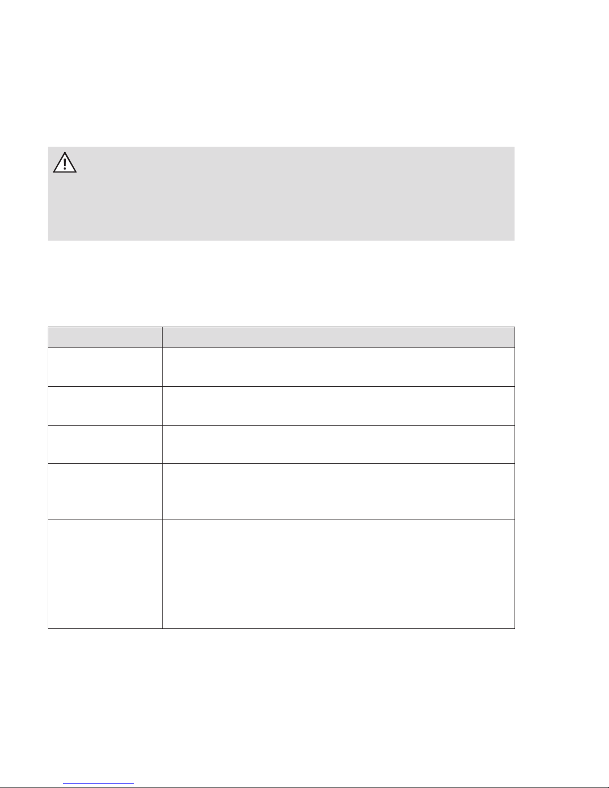
Care and disposal instructions
DANGER!
Contact of parts under voltage is extremely dangerous!
When cleaning the housing of the meter, the conductor to which the
meter is connected must be de-energized.
Clean the housing with a dry cloth. Do not use chemical cleaning
agents!
The following table lists the components and how to handle them at the
end of their life cycle:
Components Waste collection and disposal
PCB‘s Electronic waste: dispose in accordance with local
regulations.
LEDs,
LC display
Special waste: dispose in accordance with local
regulations.
Metal parts Scrap, recyclable: separate according to type and
recycle.
Plastic parts Separate according to type and recycle (re-granula-
te). Send for waste incineration if necessary (energy
generation by thermal process).
Batteries When disposing you have to take safety measures
to prevent short circuit. Dispose the batteries inside
the original package or insulate the terminals. Do
not throw the batteries into the domestic waste, but
dispose them correctly in accordance with the local
waste and environmental regulations.
Basic safety notes
The following safety notes have to be observed in principle:
• Observe the local standards, guide lines, regulations and instruc-
tions for safety at work and electrical installations.
4
• Choose the conductor cross section corresponding to the maximum
current loading.
• Provide exible wires with ferrules.
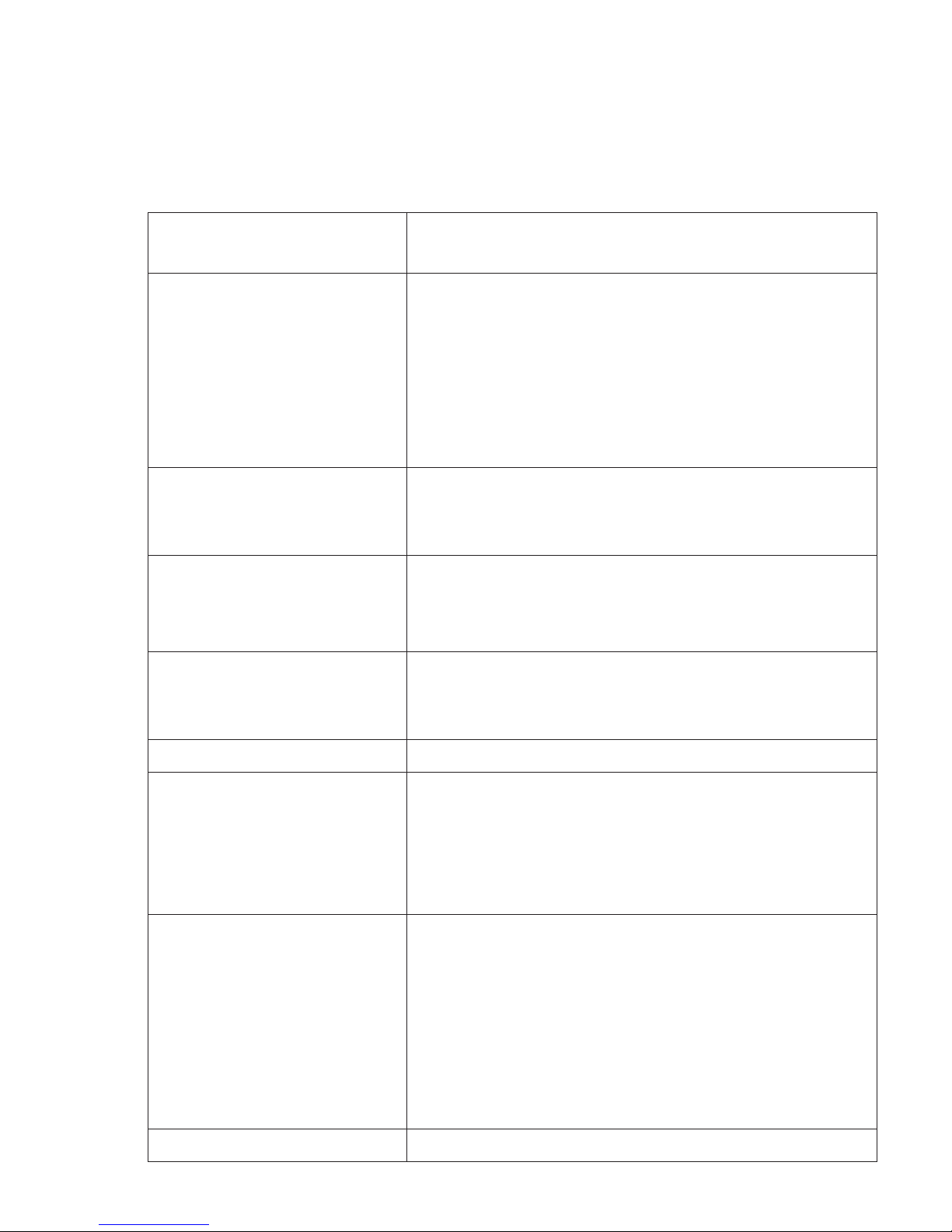
Technical data
Voltage, current,
frequency
see nameplate
Inputs
S0-input
low voltage
or system voltage
maximum number: 1, max. 27 V DC, 27 mA
(not potential-free)
maximum number: 8, 18...40 V DC
maximum number 8, 58...240 V AC
Outputs
Opto-MOSFET
maximum number: 8, max. 250 V AC/DC,
100 mA (make contact)
Temperature range specied operating range: -25 °C...+55 °C
limit range for operation, storage and
transport: -40 °C...+70 °C
Relative humidity max. 95 %, non-condensing, accor-
ding to IEC 62052-11, EN 50470-1 and
IEC 60068-2-30
Class of protection I
Degree or protection
housing
terminals
housing material
IP 50
IP 20
aluminium alloy, polycarbonate, without
halogen
Environmental condi-
tions
mechanical: M1 according to Measuring Ins-
truments Conditions Directive (2014/32/EU)
electromagnetic: E2 according to Measuring
Instruments Conditions Directive (2014/32/
EU)
intended location: indoor according to EN
50470-1
Weight approx. 2,3 kg
5
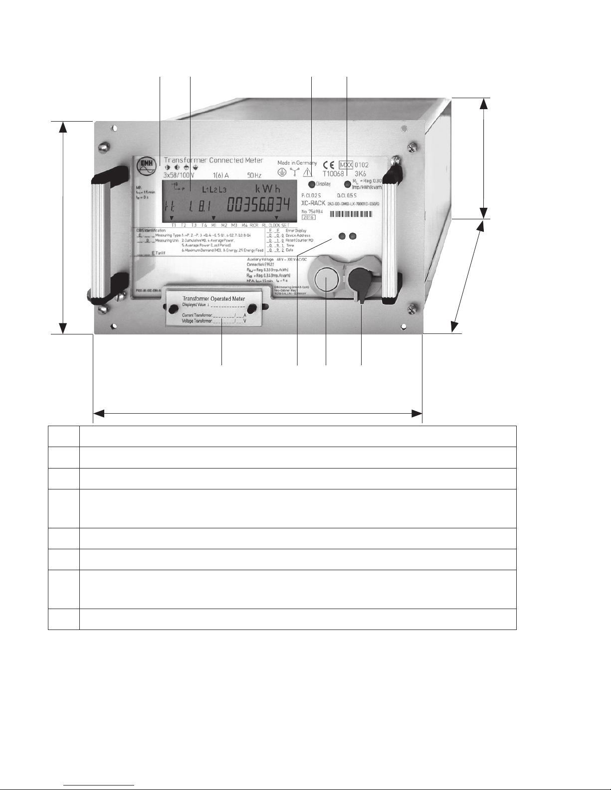
Housing, display and operating elements
1 Nameplate
2 LC display
3 Call-up sensor (optical)
4 Test-LED (continuously lit-up = no energy consumption or incor-
rect ow direction)
5 Reset button (sealable)
6 Call-up button
7 Optical data interface (D0) with magnetic xing for the optical
communication head
8 Sealable transformer plate
21 3 4
8 67 5
203 mm
132,5 mm
112 mm
264 mm
6
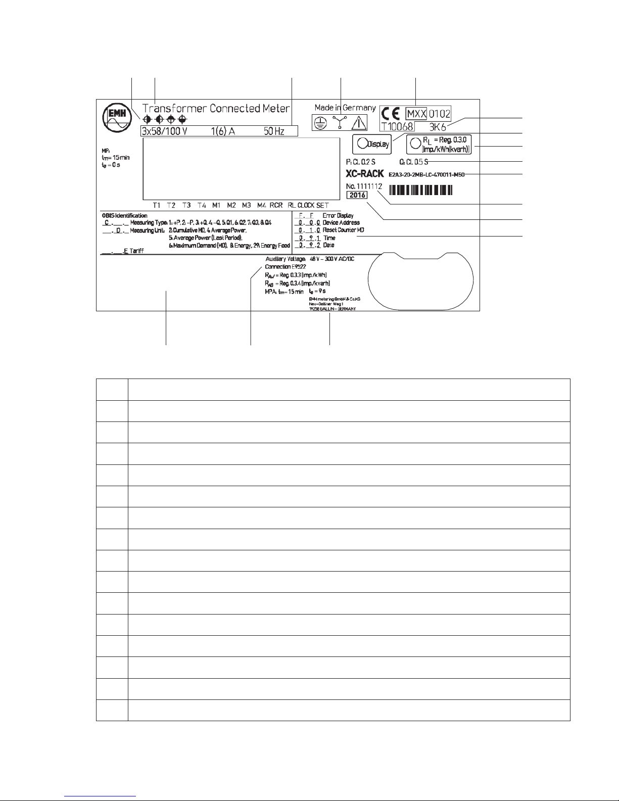
Nameplate
1 Registered quadrants
2 Type designation
3 Voltage, current, frequency
4 Safety and instruction notes
5 Conformity and approval mark
6 Temperature class according to IEC 60721-3-3
7 Call-up sensor (optical)
8 Test-LED
9 Accuracy class
10 Type key
11 Serial number
12 Model year
13 OBIS-index of the most important registers
14 Manufacturer address
15 Contact sequence number
16 Space for ownership inscription
6
7
11
12
13
8
9
10
2 3 4 51
1516 14

7
Display
1. The operation display shows the current direction of energy as
measured by the meter (export/import of active energy, export/im-
port of inductive/capactive reactive energy). If current is owing it is
possible to see in which quadrant is being measured by means of
the energy direction arrow:
1. quadrant +P/+Q 3. quadrant –P/–Q
2. quadrant –P/+Q 4. quadrant +P/–Q
2. The battery status display shows the charging status of the buffer
battery of the real time clock. The following display are possible:
= Full voltage, real-time clock is buffered when there is no
voltage
= discharged, no buffering of the real time clock is possible
The battery status display appears only with devices with a
battery-bufered Real Time Clock.
3. The communication display is continually lit-up when there
is communication with the meter via data interfaces (optical or
electrical) or the display ashes when the parameterisation status
is active. At a XC-Rack with LMN-interface the Display lights up in
irregular intervals, because it communicated intern, to provide the
collection of the data by SMGW.
INST
PWR
T1 T2 T3 T4 M1 M2 M3 M4 RCR RL CLOCK SET
1 2 4 5 63
8 79

8
4. The phase display signalises connection of the individual phase
voltages. With an incorrect rotating eld all three symbols ash.
5. The unit is displayed corresponding to the measured energy type or
the displayed measured value.
6. In the additional cursor eld operation conditions of the meter are
represented. The black arrows show if an installation error has been
registered or if the power threshold has been exceeded.
INST The cursor is active if an entry has been registered in the
installation check register.
PWR The cursor is active, if a power threshold set in the meter
is exceeded.
7. In the standard cursor eld operation conditions of the meter are
represented. The black arrows show which tariff and maximum
demand is active and via which hardware (clock or ripple control
receiver) the meter is controlled.
T1 - T4 Tariff information for energy. All tariff registers which can
be activated are displayed on the nameplate.
M1 - M4 Tariff information for maximum demand. All tariff registers
which can be activated are displayed on the nameplate
RCR The cursor ashes, when the internal ripple control recei-
ver is activated and ready to receive. The relevant cursor
is continually active when the internal RCR receives a
telegram.
RL The cursor ashes for the duration of the activation of a
reset inhibition.
CLOCK The cursor is active, if the internal clock controls the tariff
device.
SET The cursor is active, when the meter is in the set mode.
8. In the value area the measured values are represented.
9. In this OBIS code area the measured values are dened by means
of the OBIS code. The display is capable of displaying the long
OBIS code.

9
DANGER!
Contact of parts under voltage is extremely dangerous!
When installing or changing the meter, the conductor to which the
meter is connected must be de-energized.
• Remove the relevant back-up fuses, for two-sided supply on the
mains side as well as on the generation side.
• Store the back-up fuses in such a way that other people cannot
ret them unnoticed.
• If you use selective circuit breakers for disconnection from the
mains, secure them against being switched on again unnoticed.
• Only use the dedicated screw terminals for installation and connection of the meter.
Installation and commissioning
DANGER!
Risk of danger to life due to electric arc and electric shock!
The in- and outputs including the external power supply inputs are not
secured internally.
• Secure the inputs/external power supply inputs with back-up fuses
of ≤ 0,5 A according to valid technical directives.
• Secure the outputs in compliance with the current value speci-
ed on the nameplate of the meter according to valid technical
directives.
NOTICE!
Damage of the terminals due to excessive torque!
The appropriate torque depends on the type of the connection line and
on the maximum current.
• Tighten the terminals with the required torque according to
IEC 60999-1.

10
DANGER!
Contact of parts under voltage is life endangering!
S0-inputs are not potential-free. The S0-inputs are, depending on the
voltage version, internally electrical connected to the measurement
connections or to the auxiliary voltage and therefore potential carrying.
• Observe the device-specic wiring diagram inside the terminal
cover.
Mounting an connection
The meters are suitable for mounting in a 19″ racks.
DANGER!
Low voltage inputs are separated from hazardous live voltages only
by basic insulation. Therefore the low voltage inputs should not be
accessible under normal operational conditions.
The valid wiring diagram can be found on the top of the meter and also
in the delivery documents. Please refer also to the chapter “installation
check register C.86.0“ on page 14.
Transfomer operated meter for connection to current and voltage
transformers in four-wire systems.
A A A A A AB B B B
01 1 1 02 2 2 03 33 0
L1
L2
L3
u u u
x x x
X XX
UUU
k k k
K K KL L L
4020
11
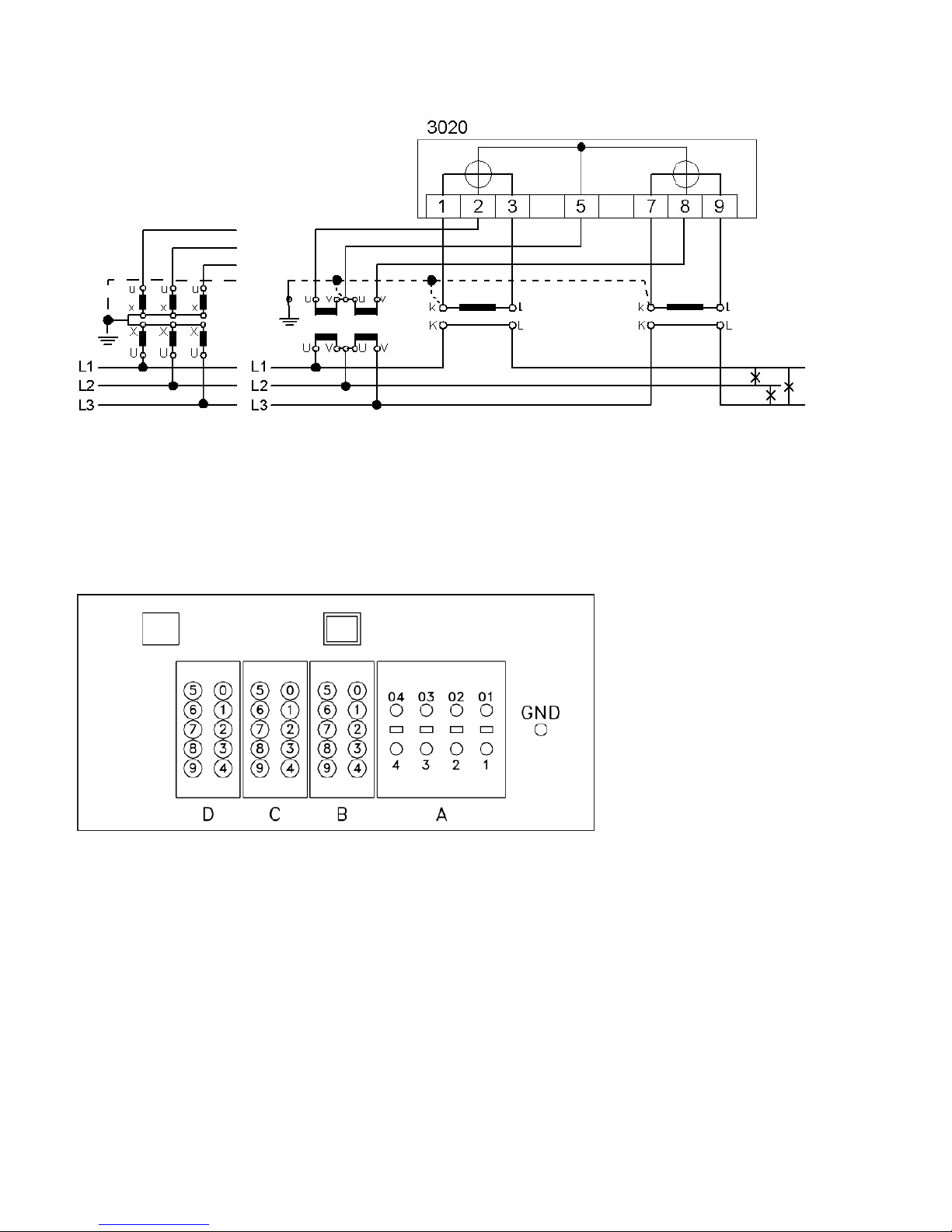
Transformer connected meter for connection at current and
voltage transformers in three-wire systems (Aron circuit).
The terminals of the meter are at the back. Following variants for connecting the meter are available:
a) Meter with Essailec-plug-in system
Communication interface
Optical bre interface
LLS

12
The conguration of the contacts is variable and can be set by the
customer. For example:
Contact Meaning Contact Meaning
D0 RS485 B+ C0 A+ GND
D5 RS485 A- C1 A+ Pulses
D1 RS485 GND C3 R+ Pulses
D2 S0- C4 R+ GND
D7 S0+ C5 A- Pulses
D4 MPA+ C6 A- GND
D9 MPA- C8 R- Pulses
C9 R- GND
Contact Meaning Contact Meaning
B0 N = Neutral A1 - A01 Current phase 1
B1 Voltage phase 1 A2 - A02 Current phase 2
B2 Voltage phase 2 A3 - A03 Current phase 3
B3 Voltage phase 3
B5 Auxiliary voltage
B6 Auxiliary voltage
b) Meter with Sub-D plug
Communication interface
Optical bre interface
LLS
The conguration of the Essailec contacts is variable and can be set as
shown above. Pin assignment of the Sub-D plug is x:
Contact Meaning
5 GND
3 RS485 B+
8 RS485 A-

13
c) Meter with Phoenix screw-type terminals
Ethernet interface
Optical bre interface LLS
The conguration of the contacts is variable and can be set by the
customer. For example:
Contact Meaning Contact Meaning
1
Current phase 1 In
3
Current phase 1 Out
4
Current phase 2 In
6
Current phase 2 Out
7
Current phase 3 In
9
Current phase 3 Out
2
Voltage phase 1
20
S0+
5
Voltage phase 2
21
S0-
8
Voltage phase 3
27
RS485 A-
11
N = Neutral
28
RS485 B+
40
GND pulses
29
RS485 GND
41
A+ Pulses
37
MPA+
42
A- Pulses
35
MPA-
43
R+ Pulses
90
GND pulse inputs
44
R- Pulses
91
Pulse input 1
92
Pulse input 2
93
Pulse input 3
94
Pulse input 4

14
Installation check register C.86.0 (optional)
The installation check register C.86.0 registrates installation errors.
Normally, it is shown in the scrolling list or can be called up via the callup list.
Not used
Wrong phase sequence
Phase failure
Negative energy direction
Current interruption
Max. current exceeded
Undervoltage
Overvoltage
Event Value Meaning
Wrong phase sequence
1
Loss of neutral
2
Wrong phase sequence
4
Assymetric current, e. g. 30 %
8
Assymetric voltage, e. g. 18 %
Phase failure
1
Phase failure L1
2
Phase failure L2
4
Phase failure L3
8
Failure of auxiliary supply voltage
Negative energy
direction
1
Negative energy direction L1 (P)
2
Negative energy direction L2 (P)
4
Negative energy direction L3 (P)
Current interruption
1
Current interruption L1
2
Current interruption L2
4
Current interruption L3
Maximum current
exceeded
(I > Imax)
1
Maximum current exceeded L1
2
Maximum current exceeded L2
4
Maximum current exceeded L3
15
Event Value Meaning
Undervoltage
(U < 80 %)
1
Undervoltage L1
2
Undervoltage L2
4
Undervoltage L3
Overvoltage
(U > 115 %)
1
Overvoltage L1
2
Overvoltage L2
4
Overvoltage L3
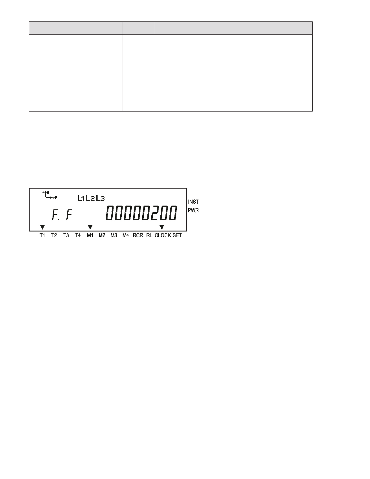
Error register F.F
The meter has 32 error ags which are represented by a 8 digit Hex-
code. With the help of this register, functional errors in the meter are
registered. Output of the error register takes place via the display and
one of the readout lists.
Clearing the error register
To clear the error register use the W5-write command F.F(). To be able
to execute this command the meter must be in the parameterisation
status. After carrying out the command the parameterisation status is
switched off.
Further informations about the error register F.F refer to the product
manual.

16
Abbreviations
DIN Deutsches Institut für Normung e.V.
(German Institute for standards)
EN European standards
GND Ground
IEC International Electrotechnical Commission
IP Ingress Protection
L1, L2, L3 External conductor
LC Liquid Crystal
LED Light Emitting Diode
OBIS Object-Identication-System
P Active power
+P Positive active power (customer imports from utility)
-P Negative active power (customer exports to utility)
PCB Printed Circuit Board
Q Reactive power
+Q Positive reactive power
-Q Negative reactive power
RCR Ripple control receiver
S0 Interface according to IEC 62053-31

17
The current EU Declaration of Conformity can be found in the
download area of www.emh-metering.com.
EU Declaration of Conformity

18

19

20
 Loading...