

Page 1
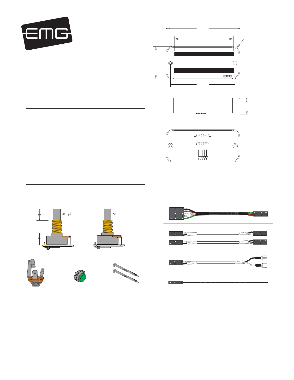
MAXIMUM RECOMMENDED STRING WIDTH 2.50"
3.712
(94.28)
2.900
(73.65)
R .375 TYP
(9.52)
PO BOX 4394
SANTA ROSA, CA
95402 USA
0230-0211C
P (707) 525-9941
F (707) 575-7046
EMGPICKUPS.COM
INSTALLATION INFORMATION
EMG MODELS: TB-HZ PICKUP
SPECIFICATIONS: MODEL:
TB-HZ
Logo Color Silver
Magnet Type * A/S
Inductance (Henries) (1) 2.65
DC Resistrance (kOhm) 8.0
Resonant Frequency (KHz) (2) 2.85
Resonant Frequency (KHz) (3) 4.90
Impedance at Resonance (kOhm) (2) 47.50
*Note: Magnet Type: A (Alnico) A/S (Alnico/Steel)
(1) Wired in Series
(2) Loaded with 500K Volume and Tone with a 20’ (6M) Cable
(3) Loaded with 1 MegOhm / 47pf
Included with THE PICKUP:
1.650
(41.91)
3.250
.125”(3.17) DIA. MOUNTING HOLES
Pin 1 Green (GRN)
Pin 2 White (WHT)
Pin 3 Braid (GND)
Pin 4 Red (RED)
Pin 5 Black (BLK)
(82.55)
EMG-HZ WIRING
COIL 1
COIL 2
12345
_
_
BLACK RED
+
WHITE
+
GREEN
.90
(22.85)
1 VOLUME CONTROL (250K)
.390
(10)
MONO OUTPUT
JACK
SOLID
BRIDGE GROUND
CONNECTOR
1 TONE CONTROL (250K)
(6).235
SOLID
ADJUSTMENT SCREWS (8)
PICKUP CABLE 15” (38cm)
2 CONNECT CABLES 5.5” (14cm)
OUTPUT CABLE 6” (15cm)
BRIDGE GROUND WIRE 6” (15cm)
Installation notes:
The connector system allows an easy method of interchanging pickups. The SRO 5-Wire Cable and wire legend are compatible with all other
EMG-HZ Pickups, so any EMG-HZ Passive Pickup can be installed with any other EMG-HZ Pickup. The 5-Wire cable allows Series/Parallel switching
or simple single/dual-coil combinations can be used. For more information go to http://www.emgpickups.com.
SPECIAL NOTE: The Red Wire of the HZ Pickup is NOT for battery power, it is a coil wire.
Warranty
All EMG Pickups and accessories are warranted for a period of two years. This warranty does not cover failure due to improper installation, abuse or damage. If
upon examination the pickup is determined to be defective, a replacement will be made. Warranty replacement products are covered by this same warranty. This
warranty covers only those pickups and accessories sold by authorized EMG Dealers. This warranty is not transferable.
© 2014 Copyright EMG INC. All Rights Reserved.
Page 2
Installation Instructions:
EMG Models: TB-HZ
General Notes:
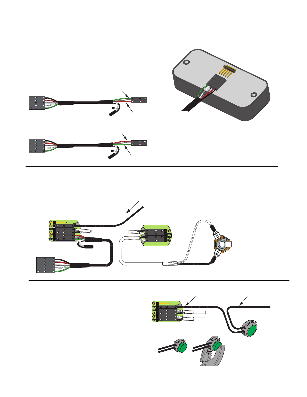
Diagram #1 shows the installation of the Pickup Cable.
Be sure to install it with the terminals as shown in the diagram.
Diagram #2 shows the Pickup cable itself. The cable is pre- wired
as shown for “Series” wiring typical of Humbucking Pickups.
If you wish to reverse the phase of the signal refer to Diagram #3.
Send the Red wire to ground with the Shield and use the Green wire
for output. In both cases the Black and White wires are hooked together
and covered with an insulator.
Diagram #1
Diagram #2
GREEN AND SHIELD
(TO GROUND)
BLACK AND WHITE
Diagram #3
(Reverse Phase)
RED AND SHIELD
(TO GROUND)
BLACK AND WHITE
Common Wiring Diagrams:
Included in this data sheet are the most common wiring diagrams.
The first diagram features wiring for a single pickup, while the
rest are for guitars with 2 Pickups and 2 styles of selection switch.
Diagram #4
One Pickup
One Volume
One Tone
MASTER
VOLUME
VOLUME250K
BLACK WIRE INCLUDED
WITH CONNECTOR FOR
BRIDGE GROUND
RED
(OUTPUT)
GREEN
(OUTPUT)
MASTER
TONE
B160A
EMG
OUTPUT
B159A
FROM PICKUP
Attaching the bridge ground wire
6) Refer to Diagram #5
As mentioned on page 1, it is common to “ground” (earth)
the strings on guitars that have passive pickups.
Included with the system is a black wire with a single black
connector attached. Also included is an IDC connector for
connecting the two wires together. Insert the bridge ground wire,
and the connector wire into the IDC connector, crimp the connector
with a pair of pliers until it snaps and this will connect the two wires.
You don’t need to strip the insulation from the wires.
Push the black connector onto terminal 2 (GND) of the volume control
as shown in the diagram. This will ground the strings to the system.
Diagram #5
EMG-TB-HZ INSTRUCTIONS Page 2
TONE
250K
OUTPUT CABLE
NECK
VOLUME
1
2
3
4
5
6
(INSERT WIRES)
VOLUME250K
B159A
T
S
BLACK WIRE INCLUDED
WITH CONNECTOR
CRIMP
STRING GROUND WIRE
COMING FROM THE BRIDGE
CLOSED
Page 3

NECK PICKUP
****Tips and Tricks****
Start your installation by:
1) Remove the strings
2) Remove any existing Pickups and controls
(remember the order and function of each control)
3) Determine a good spot for the Pickup Buss and make sure the
cable or wires from the selection switch will reach the Pickup Buss,
4) Install the EMG Volume and Tone Controls and tighten them in.
5) Then install the pickups keeping any excess cable under the pickup
rather than in the control cavity.
BRIDGE PICKUP
Diagram #6
Two Pickups
Two Volumes
One Tone
BLACK WIRE
WITH CONNECTOR
TO STRING GROUND
VOLUME250K
B159A
BRIDGE
VOLUME
NECK
VOLUME
If your instrument has a selection switch:
Shown below is the EMG B245 Pickup Buss which is used for
instruments that have 2 pickups and a 3 position selection switch.
If you have a selection switch and want your installation to
remain solderless, you’ll need a B245 Buss.
Either send an e-mail to: sales@emgpickups.com
or call: 800 821-1446 to get the buss.
1) Install the Pickups and route the Pickup cables to the control cavity.
If the cables are too long, wind up the excess and keep it under the pickup.
2) Mount the Volume and Tone controls into the body.
Plug both Pickup cables into the Pickup Buss (BLACK Shroud) as shown,
Refer to Diagram #7
Bridge Pickup to BR IN
Neck Pickup to NK IN
3) Plug a coax cable from the Pickup Buss (OUT) to the Master Volume
control as shown in the diagram.
GROUND
MASTER
TONE
B160A
EMG
OUTPUT
TONE
250K
T
S
OUTPUT CABLE
****Tips and Tricks****
Start your installation by:
1) Remove the strings
2) Remove any existing Pickups and controls
(remember the order and function of each control)
3) Determine a good spot for the Pickup Buss and make sure the
cable or wires from the selection switch will reach the Pickup Buss,
4) Install the EMG Volume and Tone Controls and tighten them in.
5) Then install the pickups keeping any excess cable under the pickup
rather than in the control cavity.
B245 BUSS
NECK P/U
OUTPUT
BRIDGE P/U
Diagram #7
2 Pickups
Toggle Style Select Switch
Master Volume / Master Tone
BRIDGE PICKUP
NECK PICKUP
Wiring the Selection Switch
4) Refer to diagrams 8 and 8a, strip the insulation from the switch wires and Insert
them into the GREEN Terminal Block and tighten the screws with a small screwdriver.
The Bridge pickup to the BR Terminal
The Neck pickup to the NK Terminal
The Output of the switch to the O Terminal
If there is a ground wire coming from the switch, insert it into one of the
black (GND) terminals on the terminal block.
Diagram #8
FROM
SWITCH
GND
O
NK
EMG
245B
BR
BRIDGE GROUND
SEE DIAGRAM #5
Diagram #8a
MASTER
VOLUME
B159A
VOLUME250K
MASTER
TONE
B160A
TONE
OUTPUT CABLE
EMG
250K
6
5
4
3
2
1
OUTPUT
T
S
EMG-TB-HZ INSTRUCTIONS Page 3
Page 4

GROUND
NECK P/U
OUTPUT
BRIDGE P/U
BRIDGE PICKUP
TO STRING GROUND
SEE DIAGRAM #5
MASTER
VOLUME
EMG
B159A
VOLUME250K
OUTPUT
6
5
4
3
2
1
T
S
Diagram #9
2 Pickups
Toggle Style Switch
Master Volume
Master Tone
GROUND
NECK P/U
OUTPUT
BRIDGE P/U
Diagram #10
2 Pickups
Toggle Style Switch
Volume each Pickup (Volumes are independent)
Master Tone
NECK PICKUP
NECK PICKUP
BRIDGE PICKUP
TO STRING GROUND
SEE DIAGRAM #5
MASTER
TONE
B160A
TONE
OUTPUT CABLE
MASTER
TONE
B160A
TONE
NK VOLUME
B159A
VOLUME250K 500K
BR VOLUME
B159A
VOLUME250K
OUTPUT CABLE
EMG
250K 500K
EMG
250K 500K
EMG
EMG
6
5
4
3
2
1
S
T
OUTPUT
Soldering to the 151 Panel Jack:
If your instrument has a long Panel Jack like the one below
you will have to solder the output cable as shown.
Ground (Black) to the Sleeve
Signal (White) to the Tip
Diagram #7
TIP
FROM TONE
OR VOLUME
SLEEVE
 Loading...