

Page 1

REV 9/04
RLH
Installation Information
EMG Model MMTW (Dual Mode)
The MMTW is a DUAL Mode pickup. It can be switched from single coil to dual coil outputs.
Specifications:
Logo Color . . . . . . . . . . . . . . . . . . . Copper
MMTW (as seen from the side)
Output Impedance (K ohms) . . . . . . . . . 10
Current @ 9VDC (Microamps) . . . . . . . . 152
Battery Life (Hours) . . . . . . . . . . . . . . . 3290
C1 C2
C3
Single Coil Dual Coil
Resonant Frequency (Khz) . . . . . . . . . . . 4.8 . . . . . . . . . . . . . 2.65
RMS Output Voltage . . . . . . . . . . . . . . . 0.8 . . . . . . . . . . . . . 1.25 (in the Dual Coil Mode, coils C1
Peak Output Voltage . . . . . . . . . . . . . . . 1.1 . . . . . . . . . . . . . 3.0 and C2 are used. Coils C2 and C3
Output Noise (dbV) . . . . . . . . . . . . . . . -91 . . . . . . . . . . . . . -90 are used in Single Coil Mode)
Important Installation Notes:
1) When replacing a passive pickup with the MMTW, it may be necessary to modify the instrument.
2) You can use a DPDT mini-toggle switch in place of the push/pull pot provided with the MMTW. The
mini-toggle switch should be wired in the same manner as the push/pull pot provided.
3) The MMTW uses the Quik-Connect pickup cable. When installed, the arrow on the connector should
be facing up as you look at the back of the pickup (see diagram 1 ).
General Installation Information:
1) Only one 9 volt battery is required per instrument. Use an Akaline battery (Duracell or Mallory). Additional
active EQ accessories such as the BTC, VMC, BQS, EXG, B-30, etc. do not require an additional battery.
2) The controls provided with EMG active pickups are 25K Ohm, active taper. This control value is necessary
for proper operation.
3) When installing EMG active pickups, DO NOT reconnect the bridge ground. EMG active pickups are
internally shielded, and do not require string grounding.
4) EMG active pickups have very little magnetism compared to high-impedance (Passive) pickups.
We recommend that you adjust the pickups as close to the strings as possible, without interfering
with your playing style.
Warranty:
All EMG Pickups and accessories are warranted for a period of two years. This warranty
does not cover failure due to improper installation, abuse or damage. If at any time a pickup
fails to work, return it postage prepaid with proof of purchase. If upon examination the pickup
is determined to be defective, a replacement will be made at no charge. Warranty replacement products are covered by this same warranty. This warranty covers only those pickups
and accessories sold by authorized EMG Dealers. This warranty is not transferable.
© Copyright EMG Inc. 2003
P.O. BOX 4394
SANTA ROSA,CA
95402 U.S.A.
PH (707) 525-9941
FX (707) 575-7046
www.emgpickups.com
Page 2
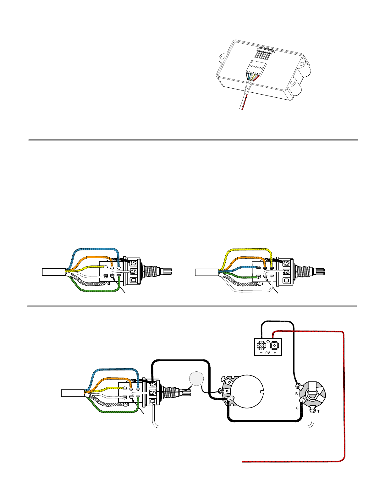
Diagram 1:
Quik-Connect cable orientation.
The Quik-Connect cable should be installed as shown,
with the arrow on the connector facing up.
Connector sequence (Arrow as Pin 1):
Orange (pin 1)
Blue (pin 2)
Green (pin 3)
Bare (pin 4)
Yellow (pin 5)
White (pin 6)
Red (pin 7)
Diagrams 2A / 2B:
These two diagrams show how the push/pull pot can be wired two different ways. Diagram 2A shows the
switch wired so that when the knob is up, the dual coil is on, and when the knob is down, the single coil is on.
In Diagram 2B, when the knob is up the single coil is on, and when the k nob is down, the dual coil is on.
NOTE: There are two separate pickups in the MMT W housing, and each pickup has two wires. The single
coil uses the white and yellow wires, and the dual coil uses the green and blue wires.
DIAGRAM 2A DIAGRAM 2B
Knob up: Dual coil on Knob up: Single coil on
Knob down: Single coil on Knob down: Dual coil on
Blue
Blue
Blue
Orange
Orange
Orange
Yellow
White
White
White
Shield
Green
Green
E MG-MMT W Dia g r am 3
1Volume,1Tone
Orange
Orange
Orange
Yellow
Yellow
Yellow
White
White
White
Blue
Blue
Blue
Pickup Output
Pickup Output
Pickup Output
Volume
0.1mf
Yellow
Orange
Orange
Orange
Blue
Green
Tone
Shield
White
Black
Pickup Output
Pickup Output
Pickup Output
Red
B o ttom V i e w
Shield
Green
Green
Green
Pickup Output
Pickup Output
Pickup Output
Note: Connect red wire from pickup cable to red wire of battery clip.
 Loading...