

EMG MARTY FRIEDMAN MF Series, MARTY FRIEDMAN MF-N5, MARTY FRIEDMAN MF-B5 Installation Information
Page 1

1.50
(38.1)
2.75
(69.8)
.39 (9.9) TYP
PO BOX 4394
SANTA ROSA, CA
95402 USA
0230-0322
P (707) 525-9941
3.09
(78.5)
3/48 MOUNTING HOLES
F (707) 575-7046
EMGPICKUPS.COM
INSTALLATION INFORMATION
EMG MODEL: MARTY FRIEDMAN - MF SET
SPECIFICATIONS: MODEL:
MF-N5 (NECK) MF-B5 (BRIDGE)
Logo Color Gold Gold
Magnet Type Alnico 5 Alnico 5
Gauss Strength 275 275
Inductance (Henries) (1) 4.3 8.58
DC Resistance (kOhm) 7.55 16.2
Q .44 .39
Resonant Frequency (KHz) (2) 3.00 2.25
Resonant Frequency (KHz) (3) 4.54 3.39
Impedance at Resonance (kOhm) (2) 81 121
(1) Wired in Series
(2) Loaded with 500K Volume and Tone with a 20’ (6M) cable
(3) Loaded with 1 MegOhm / 47pf
Installation notes:
All EMG-Passive Pickups are compatible with each other. The connector system is an easy method of installation, avoiding the need to solder.
EMG Accessory Circuits like the VLPF, EXG, SPC or RPC Controls can be added to any EMG Passive System, all EMG Accessory circuits have
buffered inputs and can be used on either passive or active pickups.
SPECIAL NOTE: The Red Wire of the HZ Pickup is NOT for battery power, it is a coil wire.
.900
(22.8)
EMG COIL WIRING
FINGERBOARD PICKUP
COIL 1
SCREW BOBBIN
COIL 2
STUD BOBBIN
_
_
RED
WHITE GREEN
+
BLACK
+
BLACK RED
WHITE
.725 (18.4)
BRIDGE PICKUP
COIL 2
+
STUD BOBBIN
COIL 1
+
SCREW BOBBIN
_
_
GREEN
Included IN THE MF SET:
2 VOLUME CONTROLS (500K)
2 TONE CONTROSL (500K)
.390
(10)
MONO OUTPUT
JACK
(6)
.235
.310
(8)
BRIDGE GROUND
CONNECTOR
ADJUSTMENT
SCREWS & SPRINGS
2 PICKUP IN/ OUT
BATTERY BUSS
B245
PICKUP CABLES 15” (30cm)
4 CONNECT CABLES 5.5” (14cm)
OUTPUT CABLE 6” (15cm)
BRIDGE GROUND WIRE 6” (15cm)
Warranty
All EMG Pickups and accessories are warranted for a period of two years. This warranty does not cover failure due to improper installation, abuse or damage. If
upon examination the pickup is determined to be defective, a replacement will be made. Warranty replacement products are covered by this same warranty. This
warranty covers only those pickups and accessories sold by authorized EMG Dealers. This warranty is not transferable.
© 2016 Copyright EMG INC. All Rights Reserved.
Page 2

Installation Instructions:
EMG Models: MARTY FRIEDMAN MF - SET
General Notes:
Every attempt has been made to make this a solderless installation.
There are some instances where this is not possible;
1) If your instrument uses the long panel output jack, soldering will be required
2) Instruments with two pickups may need soldering to the selection
switch in some installations.
If you are installing only one pickup use the instructions on this page.
If you are installing two pickups go to page 3 and begin there.
Installation (One Pickup Guitars):
1) Plug the pickup cable onto the EMG Pickup header as shown
in Diagram #1 and route the cable to the control cavity.
If the cable is too long, wind up the excess and keep it
under the pickup if possible.
Diagram #2 shows the factory pre-wired cable. The Green
wire and shield are pre-wired to Pin 1 and the Red wire is
pre-wired to Pin 2. The Red wire is the signal output from
the pickup. The White and Black wires are wired together and
covered with shrink tubing. This is standard humbucking series
wiring.
Diagram #1
Diagram #2
RED
EMG-HZ Wire Order:
Pin 1 Green (GRN)
Pin 2 White (WHT)
Pin 3 Braid (GND)
Pin 4 Red (RED)
Pin 5 Black (BLK)
BLACK AND WHITE
GREEN AND SHIELD
Master Volume control only
2) Refer to Diagram #3.
Plug both the Pickup cable and the output
cable onto the Volume control as shown, then go to step 4.
Master Volume and Tone control
3) Refer to Diagram #4.
Plug the Pickup cable onto the Volume
control as shown. Plug a coax cable from the Volume control
to the Tone control. Plug the output cable onto the tone
control as shown.
4) Connect the wires of the output cable to the output jack by
pushing the connectors on as shown.
WHITE wire to the TIP (T) contact,
BLACK wire to the SLEEVE (S) contact
We suggest that you plug in the instrument and
test it before closing the control cavity.
MASTER
VOLUME
Diagram #4
One Pickup
One Volume
One Tone
Diagram #3
One Pickup
One Volume
VOLUME250K 500K
B159A
MASTER
VOLUME
VOLUME250K 500K
B159A
FROM PICKUP
TO STRING GROUND
SEE DIAGRAM #5
TO STRING GROUND
SEE DIAGRAM #5
MASTER
TONE
B160A
TONE
OUTPUT CABLE
OUTPUT CABLE
EMG
250K 500K
OUTPUT
T
S
OUTPUT
T
S
FROM PICKUP
Attaching the bridge ground wire
6) Refer to Diagram #5.
As mentioned on page 1, it is common to “ground” (earth)
the strings on guitars that have passive pickups.
Included with the system is a black wire with a single black
connector attached. Also included is an IDC connector for
connecting the two wires together. Insert the bridge ground wire,
and the connector wire into the IDC connector, crimp the connector
with a pair of pliers until it snaps and this will connect the two wires.
You don’t need to strip the insulation from the wires.
Push the black connector onto terminal 2 (GND) of the volume control
as shown in the diagram. This will ground the strings to the system.
MF SET INSTRUCTIONS Page 2
Diagram #5
1
2
3
4
5
6
NECK
VOLUME
VOLUME250K
B159A
(INSERT WIRES)
BLACK WIRE INCLUDED
WITH CONNECTOR
CRIMP
STRING GROUND WIRE
COMING FROM THE BRIDGE
CLOSED
Page 3
Installation Instructions:
****Tips and Tricks****
Start your installation by:
1) Remove the strings
2) Remove any existing Pickups and controls
(remember the order and function of each control)
3) Determine a good spot for the Pickup Buss and make sure the
cable or wires from the selection switch will reach the Pickup Buss,
4) Install the EMG Volume and Tone Controls and tighten them in.
5) Then install the pickups keeping any excess cable under the pickup
rather than in the control cavity.
EMG Models: MARTY FRIEDMAN - MF SET
Installation (Two Pickup Guitars with Selection switch):
Guitars with two pickups and a selection switch will use the EMG B245 Pickup Buss.
The Pickup Buss is a convenient way to wire your guitar without soldering.
There is a separate sheet attached to these instructions that describes the
Pickup Buss in detail. Since you are installing passive EMG-HZ Pickups the RED
Shroud of the B245 Pickups Buss will not be used. It is for battery power.
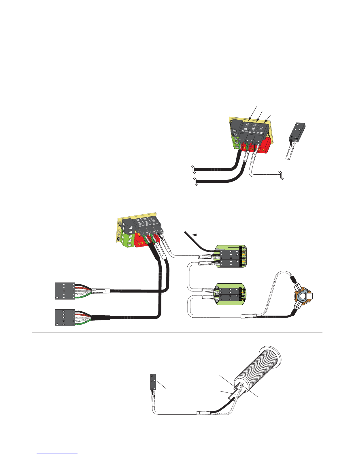
2 Pickups / Toggle Select Switch / Master Volume and Tone
1) Install the Pickups and route the Pickup cables to the control cavity.
If the cables are too long, wind up the excess and keep it under the pickup.
2) Mount the Volume and Tone controls into the body.
Plug both Pickup cables onto the Pickup Buss (BLACK Shroud) as shown,
Refer to Diagram #6a
Bridge Pickup to Position 1
Neck Pickup to Position 2.
3) Plug a coax cable from the Pickup Buss (Position 3) to the Master Volume
control as shown in Diagram #6b.
4) Plug a coax cable from the Master Volume to the Master Tone as shown.
5) Strip the insulation from the switch wires and Insert them into the GREEN
Terminal Block and tighten the screws with a small screwdriver.
The Bridge pickup goes to the BR Terminal
The Neck pickup goes to the NK Terminal
The Output of the switch goes to the O Terminal
If there is a ground wire coming from the switch, insert it into one of the black
terminals on the terminal block.
6) Plug the output cable onto the Master Tone control and connect the output
wires to the output jack by pushing the connectors on as shown.
WHITE wire onto the TIP (T) contact,
BLACK wire onto the SLEEVE (S) contact
We suggest that you plug in the instrument and test it before closing the
control cavity.
****Tips and Tricks****
Start your installation by:
1) Remove the strings
2) Remove any existing Pickups and controls
(remember the order and function of each control)
3) Determine a good spot for the Pickup Buss and make sure the
cable or wires from the selection switch will reach the Pickup Buss,
4) Install the EMG Volume and Tone Controls and tighten them in.
5) Then install the pickups keeping any excess cable under the pickup
rather than in the control cavity.
BRIDGE PICKUP INPUT
Diagram #6a
NECK PICKUP INPUT
OUTPUT
BRIDGE PICKUP
OUTPUT TO MASTER VOLUME
NECK PICKUP
PLUG IN
LIKE THIS!
Diagram #6b
2 Pickups
Toggle Style Select Switch
Master Volume & Master Tone
FROM NECK PICKUP
FROM BRIDGE PICKUP
Diagram #7
Soldering to the 152B Panel Jack:
If your instrument has a long Panel Jack like the one below
you will have to solder the output cable as shown.
Ground (Black) to the Sleeve
Signal (White) to the Tip
Battery Negative (Black) to the Ring
FROM TONE
OR VOLUME
TO STRING GROUND
SEE DIAGRAM #5
OUTPUT CABLE
RING
NOT USED
SLEEVE
TONE
B160A
6
5
4
3
2
1
EMG
MASTER
TONE
250K 500K
MASTER
VOLUME
OUTPUT
T
S
TIP
MF SET INSTRUCTIONS Page 3
Page 4

GROUND
NECK P/U
OUTPUT
BRIDGE P/U
MASTER
TONE
B160A
TONE
OUTPUT CABLE
EMG
250K 500K
OUTPUT
T
S
FROM NECK PICKUP
Diagram #8
2 Pickups
Toggle Style Switch
Volume each Pickup (Volumes are independent)
Master Tone
FROM BRIDGE PICKUP
TO STRING GROUND
SEE DIAGRAM #5
2 Pickups / Toggle Select Switch / 2 Volumes and 2 Tones)
Refer to Diagram #9
1) Install the Pickups and route the cables to the control cavity.
If the cables are too long, wind up the excess and keep it under the pickup.
2) Mount the Volume and Tone controls into the body
Plug both Neck and Bridge pickup cables onto the Volume Controls as shown.
Plug a coax cable from the Bridge (BR) Volume control to the Pickup Buss
(Position 1).
Plug a coax cable from the Neck (NK) Volume control to the Pickup Buss
(Position 2).
3) Plug a coax cable from the Bridge (BR) Volume control to the Bridge (BR) Tone
control as shown.
4) Plug a coax cable from the Neck (NK) Volume control to the Neck (NK) Tone
control as shown.
NK VOLUME
BR VOLUME
5) Strip the insulation from the switch wires and Insert them into the GREEN
Terminal Block and tighten the screws with a small screwdriver.
The Bridge pickup goes to the BR Terminal
The Neck Pickup goes to the NK Terminal
The Output of the switch goes to the O Terminal
If there is a ground wire coming from the switch, insert it into one of the black
terminals on the terminal block.
6) Plug the output cable onto the Pickup Buss (Position 3) and push the
connectors onto the jack as shown.
WHITE wire onto the TIP (T) contact,
BLACK wire onto the SLEEVE (S) contact
We suggest that you plug in the instrument and test it before closing the
control cavity.
EMG
B159A
VOLUME250K 500K
EMG
B159A
VOLUME250K
6
5
4
3
2
1
GROUND
NECK P/U
OUTPUT
BRIDGE P/U
Diagram #9
2 Pickups
2 Volume (either volume will act as a master)
2 Tone
Toggle Style Switch
FROM NECK PICKUP
FROM BRIDGE PICKUP
MF SET Instructions Page 4
OUTPUT CABLE
NK VOLUME
BR VOLUME
TO STRING GROUND
SEE DIAGRAM #5
OUTPUT
T
S
B160A
TONE
NK TONE
BR TONE
B160A
TONE
EMG
250K 500K
250K 500K
 Loading...