

EMG EMG-VMC Installation Information
INSTALLATION INFORMATION
MODEL EMG-VMC
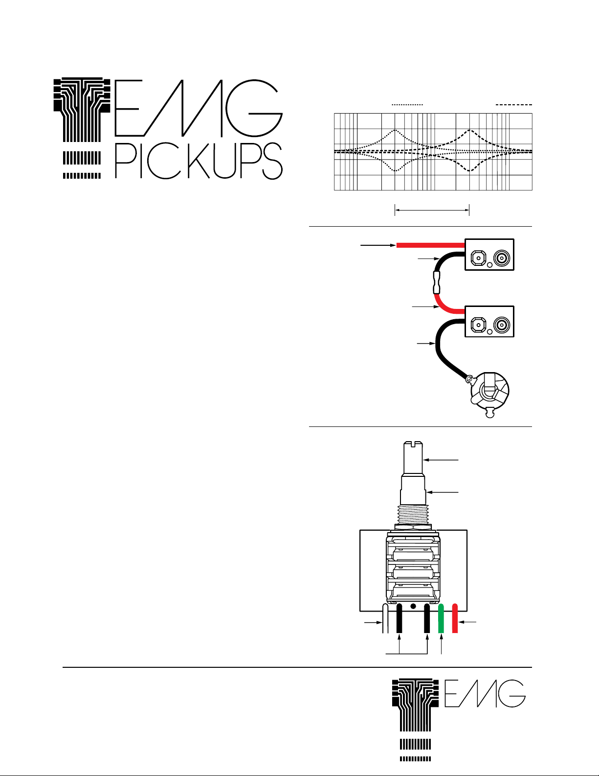
The EMG-VMC is an active EQ Circuit for guitar and
bass. Its effects are illustrated in the graph to the right.
Rotate the gain control clockwise for boost, counterclockwise for cut. Leave it in the center detent position for flat
response. Rotate the variable frequency knob to sweep
through the mid-frequency band from 300 Hz to 3000 Hz.
This allows you to select the frequency to boost or cut.
The graph to the right illustrates the low and high ends of
the mid-control.
GENERAL INSTALLATION NOTES
1)
Only one battery is required for the pickups, and any
active components such as the BTC, BTS, BQC,
VMC, PI2, and PA2. Two batteries wired in series for
18 volts is recommended for bass to increase headroom and enhance overall performance.
2)
Use an alkaline battery, MN1604 or similar, for longest
life.
3)
The original control set must be altered. This is assuming that you already have EMG Pickups in your instrument. If you are installing pickups along with an EQ
circuit, please read both sets of instructions before
you start. This should save you some steps.
4)
If your installation is different from the diagrams in
these instructions and you need additional diagrams,
call or write to us. It is highly possible another EMG
Installation Sheet will have the diagram you require.
This circuit is designed to be a building block in your
5)
bass. It can be added to any existing EMG units such
as the BTC or BTS CONTROLS. The VMC CONTROL
has five wires: input (white), output (green), battery
(red), and 2 grounds (both black). The VMC CONTROL can be wired before or after a BTC or BTS
CONTROL, but for best results we recommend that it
be wired before any other EMG accessory.
6)
You may need to modify your instrument to accommodate the VMC CONTROL. You may want to have
this done by a qualified technician as special tools
and skills are required.
Low end of
Mid Boost and Cut
10 dB/div
100 Hz 3 KHz300 Hz 10 KHz
Red Wire to
Pickups and
Accessories
18 VOLT
WIRING OPTION
VMC
White (Input)
Black (Ground)
Black
Red
Black
High end of
Mid Boost and Cut
Mid Boost/Cut
Mid Frequency
Red (Volts +)
Green (Output)
Warranty:
All EMG Pickups and accessories are warranted for a period of two years. This warranty
does not cover failure due to improper installation, abuse or damage If at any time a pickup
fails to work, return it postage prepaid with proof of purchase. If upon examination the pickup
is determined to be defective, a replacement will be made at no charge. Warranty replacement products are covered by this same warranty. This warranty covers only those pickups
and accessories sold by authorized EMG Dealers. This warranty is not transferable.
© Copyright EMG Inc. 1995
P.O. BOX 4394
SANTA ROSA, CALIF.
95402 U.S.A.
(707) 525-9941
FAX (707) 575-7046
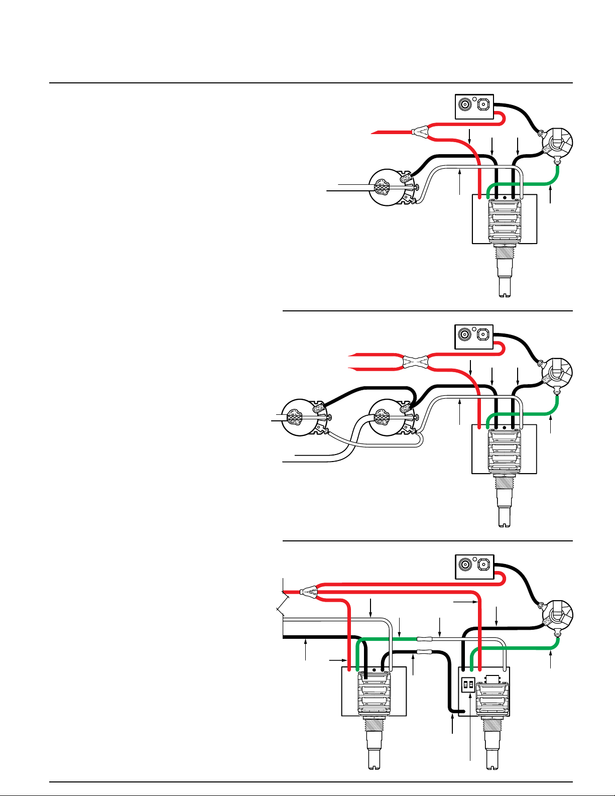
INSTALLATION INSTRUCTIONS
FOR THE VMC CONTROL
Unsolder and remove the tone control and its
1)
capacitor. Also remove the black wires going
from the tone control to the jack and from the
tone control to the volume control. They won't be
reconnected.
2)
Unsolder and remove the "Hot" wire that connects between the outer lug of the jack (tip) and
the volume control.
Mount the VMC CONTROL in the instrument.
3)
4)
Solder the white wire of the VMC CONTROL to
the volume control as shown in the diagram.
5)
Solder the green wire of the VMC CONTROL to
the jack (tip) as shown in the diagram.
Solder one black wire from the VMC CONTROL
6)
to center solder lug (sleeve) on the jack. Solder
the other black wire to the case of the volume
pot as shown in the diagram.
7)
Solder the red wire of the VMC CONTROL
together with the red wires from the pickups and
battery clip. Cover this connection with shrink
tubing.
8)
Attach the battery and test the instrument.
9)
This completes the installation. If you have any
problems, contact the factory at the number provided on the front page of these instructions.
Service is readily available.
INSTALLATION INSTRUCTIONS
FOR THE VMC CONTROL
WITH THE BTC OR BTS CONTROL
1 Volume
1 VMC
2 Volume
1 VMC
White
White
Red
Red
Black
Green
Black
Green
This diagram illustrates how to wire the VMC
1)
CONTROL together with a BTC or BTS CONTROL. Not shown is the volume pot(s) because
it is wired exactly as shown above.
Solder the white wire and one black of the VMC
2)
CONTROL to the volume pot as shown above.
3)
Solder the other black wire of the VMC CONTROL to one black wire of the BTC or BTS
CONTROL. Cover the connection with heat
shrink tube.
Solder the other black wire of the BTC or BTS
4)
CONTROL to the sleeve connection of the output jack as shown in the diagram.
Solder the green wire of the VMC CONTROL to
5)
the white wire of the BTC or BTS CONTROL.
Cover the connection with heat shrink tube.
Solder the green wire of the BTC or BTS CON-
6)
TROL to the tip connection of the output jack as
shown in the diagram.
Solder the red wire of the VMC CONTROL
7)
together with the red wires from the BTC or BTS
CONTROL, the pickups and the battery clip.
Cover this connection with heat shrink tubing.
This completes the installation. If you have a
problem contact the factory at the number on the
front of these instructions. Service is readily
available.
VMC with BTC
Black
White
Green
Red
Red
White
Black
ONON
VMC BTC
Black
High Frequency
Selector Switch
Black
Green
12
 Loading...