

Page 1

PO BOX 4394
A ROSA, CA
SANT
95402 USA
0230-0095rJ
P (707) 525-9941
F (707) 575-7046
EMGPICKUPS.COM
SOLID SHAFT
INSTALLATION INFORMATION
EMG MODEL: B125 ACTIVE BALANCE CONTROL / (ABC)
(PASSIVE/ACTIVE PICKUP INPUT)
SPECIFICATIONS
Input Impedance (Ohms) 200K
Input Referred Noise -130dbV
Output Impedance (Ohms) 2K
Current @ 9V (Microamps) 600
Battery Life (Hours) 750
Maximum Supply (Volts DC) 18
General Operation
The B125 Active Balance Control (ABC) is used to pan between two EMG-HZ pickups rather than use a selection switch. The B125 features input
buffer amps for each pickup, so if you have 2 Passive Pickups, 2 Active EMG Pickups, or are mixing an active with a passive pickup you can use
the B125 Active Balance control. Pickups can be connected by connectors or hand soldered to the PC board. The control has a center detent
(click) in its rotation.
INCLUDED:
1 B125 ABC Control
1 25K Solid Shaft Pot (Master Volume)*
1 Battery Clip with Buss Connector*
1 Stereo Output Jack (Battery Switching)*
2 Interconnect Cables (1 Red, 1 White)
* Included with your EMG Pickup.
Installation notes:
The output impedance of the ABC is low, so the existing high resistance volume and tone controls will not work when placed after the ABC.
The active tone control (VLPF) is required for tone. Any of the EMG Accessories like the EXB, BTC or BTS Controls, BQC or BQS Controls, or
OEM Models B30eq or B64eq can be added as well.
.236 (6mm)
.309 (8mm P .75)
1.00
Input (Bridge Pickup)
Ground (Bridge Pickup)
V+ (Bridge Pickup)
Input (Neck Pickup)
Ground (Neck Pickup)
V+ (Neck Pickup)
Dimensions:
B125 Active Balance
(ABC)
1.79
.974
.393
.393
1.00
Output
Ground
V+
Warranty
All EMG Pickups and accessories are warranted for a period of two years. This warranty does not cover failure due to improper installation, abuse or damage. If
upon examination the pickup is determined to be defective, a replacement will be made. Warranty replacement products are covered by this same warranty. This
warranty covers only those pickups and accessories sold by authorized EMG Dealers. This warranty is not transferable.
© 2008 Copyright EMG INC. All Rights Reserved.
Page 2
Installation Instructions:
EMG Model: B125 ABC (Active Balance Control)
.
Existing EMG-HZ Passive Pickup installations:
If you already have EMG-HZ Pickups in your instrument you can use
the existing pickup cables or you can use the new plug-in cables provided.
The new cables are pre-wired to use the pickup in the humbucking mode.
If you are using a coil-tap switch, or a phase switch, use the existing
cables and use the hand soldered method for installation (see below).
Diagrams 1, 2, and 3 illustrate how to connect the pickups to the ABC Control
by using the EMG Plug-in connectors. Diagrams 4, 5, and 6 show how to solder
the pickups to the PC Board. The output of the ABC is then illustrated in diagrams
on page 4 in a variety of configurations.
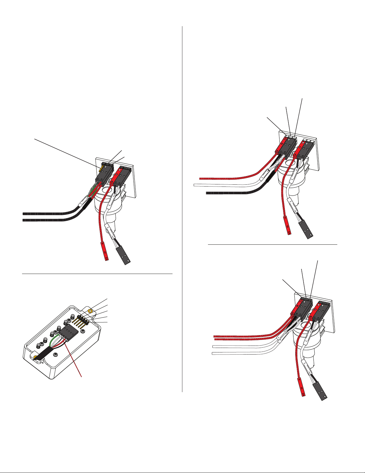
Diagram #1
EMG-HZ Plug-in Inputs & Output
Pin 1
This pin and the one below it supply 9V+ for EMG Active Pickups:
DO NOT use either pin when using passive pickups.
Pin 2 Ground for pickup
Pin 3 Input for pickup
Mixing EMG-HZ or other Passive Pickups and EMG Active Pickups:
Use either the Plug-in connector for an EMG-HZ (shown below)
or hand solder any passive pickup to the PC Board using the solder
pads provided. The EMG Active Pickup can be plugged into the chosen
3 pin input header or its cable can be soldered to the PC Board.
The Red wire (9V+) of the EMG should be plugged onto Pin 1 of the ABC
as shown or soldered to the buss connector as shown on page 3.
Diagram #2
EMG-HZ Plug-in Input (Bridge Pickup)
EMG Active Pickup Input (Neck Pickup)
Pin 3 Input for pickup
Pin 2 Ground for pickup
Pin 1 Voltage (9V+) for Active Pickups
EMG Active Neck Pickup
(Upper 3 pin header)
NECK PICKUP (White tubing)
(Upper 3 pin header)
BRIDGE PICKUP (Black tubing)
(Lower 3 pin header)
RED TO 9V + BUSS
See any EMG-HZ Data Sheet
for the coil / color codes
TO VOLUME CONTROL
EMG-HZ Wire Order:
Pin 1 Green (GRN)
Pin 2 White (WHT)
Pin 3 Braid (GND)
Pin 4 Red (RED)
Pin 5 Black (BLK)
EMG-HZ Bridge Pickup (Black tubing)
(Lower 3 pin header)
RED TO 9V + BUSS
Diagram #3
EMG Active Pickup Inputs:
Pin 2 Ground for pickup
Pin 1 Voltage (9V+) for Active Pickups
EMG Active Neck Pickup
(Upper 3 pin header)
EMG Active Bridge Pickup
(Lower 3 pin header)
TO VOLUME CONTROL
Pin 3 Input for pickup
B125 Page 2
The RED Wire of the EMG-HZ Pickup is a coil wire. It is
the signal output (hot) wire. DO NOT hook this wire to 9V+
or you will be sorry. Really sorry! If you are installing new
EMG-HZ Passive Pickups refer to those data sheets.
OUTPUT
RED TO 9V + BUSS
Page 3

Soldered Inputs:
Using the existing EMG-HZ Cables:
If you use your existing EMG-HZ cables, use diagram number #4
showing the cables hand soldered to the ABC Control.
If you have a phase switch or coil-tap on one of the EMG-HZ Pickups
the output of that switch should go to the BRG or NEK solder pad
on the ABC Control, depending on which pickup is phased or tapped.
The ground from that pickup should be soldered to the GND pad
on the ABC Control.
Diagram #4
Soldered Input using EMG-HZ Pickups
Solder Red to BRG Pad
Solder GRN and Braid to GND Pad
NK IN
V+
OUT
GND
BRG
NEK
EMG,INC. B125rC
BR IN
GND
GND
IN
V+
GND
Bridge Pickup Cable
Black Tubing
Neck Pickup Cable
White Tubing
Solder GRN and Braid to GND Pad
Solder Red to NEK Pad
Using other passive pickups:
On the back side of the ABC Board there are 4 pads to solder to.
Solder the signal wire (Hot) of your bridge pickup to the BRG Pad,
and solder the ground wire (shield) of that pickup to the GND Pad.
Do the same for the Neck Pickup, Hot to the NEK Pad, and ground
to the GND Pad.
If you have a phase switch or coil-tap on one of your pickups
the output of that switch should go to the BRG or NEK solder pad
on the ABC Control, depending on which pickup is phased or tapped.
The ground from that pickup should be soldered to the GND pad
on the ABC Control.
Diagram #5
Soldered Input using Passive Pickups
Solder Pickup Hot to BRG Pad
Solder Pickup Ground to GND Pad
NK IN
V+
OUT
GND
BRG
NEK
EMG,INC. B125rC
BR IN
GND
GND
IN
V+
GND
Bridge Pickup Cable
Neck Pickup Cable
Solder Pickup Ground to GND Pad
Solder Pickup Hot to NEK Pad
Using EMG Active Pickups:
On the back side of the ABC Board there are 4 pads to solder to.
Solder the signal wire (Hot) of the bridge pickup to the BRG Pad
and solder the shield (Braid) of the BRG Pickup to the GND Pad.
Do the same for the Neck Pickup. Solder the signal wire (Hot)
to the NEK Pad and shield (Braid) to the GND Pad.
Powering up the pickups:
When you use the soldered inputs you will need to power the pickups
with the power buss. Since your existing pickup cables don’t have the
connector for the power buss, simply use some needle nose pliers
and pull out the V+ header and solder the RED Wires of the EMG Pickups
to any of the pins on the header. Also, don’t forget to solder the RED Wire
of the battery clip to one of the header pins of the buss as well.
1
2
Solder RED wires from both
EMG Pickups and the
RED wire of the Battery Clip
and re-insert the Header
into the insulation cover
Diagram #6
Soldered Inputs using EMG Active Pickups
Solder Pickup Hot to BRG Pad
Solder Pickup Braid to GND Pad
NK IN
V+
OUT
GND
BRG
NEK
EMG,INC. B125rC
BR IN
GND
GND
IN
V+
GND
Bridge Pickup Cable
Neck Pickup Cable
Solder Pickup Braid to GND Pad
Solder Pickup Hot to NEK Pad
3
B125 Page 3
Page 4

Output of the ABC Control:
The output of the ABC is a single channel signal that is sent to a
master volume and active tone.
If you want a standard tone control (high end roll off) use the EMG-VLPF.
The following diagrams show any EMG “Active Tone” control being used
i.e. VLPF, EXG, BTC Control, BTS Control, BQC Control, BQS Control, or any
of EMG’s OEM Controls like the B30EQ or B64EQ.
Preferred wiring order:
Below is a block diagram showing the preferred wiring order of the controls.
1) ABC Balance Control
2) Active tone control
3) Master Volume
4) Output jack
NECK
PICKUP
BRIDGE
PICKUP
ABC
CONTROL
ACTIVE
TONE
MASTER
VOLUME
Diagram #7 (preferred wiring order)
ABC Control / Active Tone / Master Volume / Output Jack
- 9V +
EMG-HZ Neck Pickup
(Upper 3 pin header)
B125
ACTIVE BALANCE
CONTROL
EMG-HZ Bridge Pickup
(Lower 3 pin header)
RED
RED
OUTPUT
JACK
All of the EMG Active controls use the same color coded connector
shown below.
NOTE: Reversed connector! Pins 1 and 2 are reversed.
Make sure the connectors are plugged on as shown.
Diagram #1
Color Code for EMG Active Tone controls and accessories.
White: Input
Black: Ground for Input
Black: Ground for Output
Green: Output
Red: V+ Supply
9V+ POWER BUSS
BATTERY
MASTER
VOLUME
RED
NEG (-) BLACK
ACTIVE
TONE
NOTE REVERSED CONNECTOR!
OUTPUT
R
S
Alternate wiring order:
1) ABC Balance Control
2) Master Volume
3) Active Tone Control
4) Output jack
Diagram #8 (alternate wiring order)
ABC / Master Volume / Active Tone / Output Jack
- 9V +
EMG-HZ Neck Pickup
(Upper 3 pin header)
EMG-HZ Bridge Pickup
(Lower 3 pin header)
NECK
PICKUP
BRIDGE
PICKUP
B125
ACTIVE BALANCE
CONTROL
RED
ABC
CONTROL
RED
RED
MASTER
VOLUME
9V+ POWER BUSS
MASTER
VOLUME
ACTIVE
TONE
MASTER VOLUME AND
ACTIVE TONE REVERSED
OUTPUT
JACK
BATTERY
NEG (-) BLACK
RED
ACTIVE
TONE
BOTTOM VIEW
T
NOTE REVERSED CONNECTOR
OUTPUT
R
S
B125 Page 4
T
BOTTOM VIEW
 Loading...