

Page 1

PO BOX 4394
SANTA ROSA, CA
95402 USA
0230-0196rB
P (707) 525-9941
F (707) 575-7046
EMGPICKUPS.COM
AB
(AFTER-BURNER)
INSTALLATION INFORMATION
EMG MODEL: AB (AFTERBURNER)
(ACTIVE/PASSIVE PICKUP INPUTS)
SPECIFICATIONS
Input Impedance (Ohms) 250K
Input Referred Noise -130dbV
Output Impedance (Ohms) 2K
Current @ 9V (Microamps) 980
Battery Life (Hours) 250
Maximum Supply (Volts DC) 18
GENERAL OPERATION:
The EMG-AB is a booster pre-amp that uses a Push-Pull Pot to activate the amount of boost you want. When the Push-Pull pot is in the “down”
position there is no boost and the control has no effect. In the “up” position, rotating the pot can boost the input by up to 20dB at full rotation.
Both passive and active pickups can be used with the EMG-AB. The AB is designed to be placed last in the signal chain just before the output jack.
Also, the AB will convert a guitar with passive (High Impedance) pickups to a low impedance output.
A few notes about boosting:
The amount of “clean” boost you can get from the AB is dependent upon the amount of gain you set on the pot and the level of power
supply you have. The usual supply is 9 Volts. If you turn the pot for maximum boost (20dB) the maximum input is .70 Volts for a clean output
when supplied with a 9 Volt battery. If you turn the pot 1/2 way (10dB) the maximum input will be 1.4 Volts input for a clean output.
By increasing the power supply to 18 Volts, you can virtually double the “clean” headroom of the AB.
INCLUDED:
1 AB Control
1 Battery Clip with Buss Connector
1 Stereo Output Jack (Battery Switching)
3 Interconnect cables
As the battery voltage begins to drop from use, the amount of “Clean” headroom will diminish as well. If you want a clean boost, then replace
your battery fairly often., or operate at 18 Volts to maximize headroom. If you don’t care about how clean the signal is, but just want to blow
your mind, don’t worry about the supply voltage until you don’t get the sound you’re looking for then change the battery or... Just... Rock on!
IMPORTANT INSTALLATION NOTES:
Only one 9-Volt battery is required to power the pickups and any accessories such as the AB, SPC, EXG or other EMG Controls.
Use an Alkaline or Lithium battery for longest life. If your installation is different from the diagrams in these instructions or you need additional
diagrams visit our website: emgpickups.com for a complete listing of available diagrams.
Dimensions:
.309 (8mm P .75)
Connector for EMG Active Tone controls
and accessories.
Pin 1 Input
Pin 2 Ground for Input
Pin 3 Ground for Output
Pin 4 Output
Pin 5 V+ Supply
1.910
(48.5)
.700
(17.8)
.400
(10)
1.160
(29.5)
.740
(19)
INPUT
GROUND
GROUND
OUTPUT
V++
.810
(16.6)
Warranty
All EMG Pickups and accessories are warranted for a period of two years. This warranty does not cover failure due to improper installation, abuse or damage. If
upon examination the pickup is determined to be defective, a replacement will be made. Warranty replacement products are covered by this same warranty. This
warranty covers only those pickups and accessories sold by authorized EMG Dealers. This warranty is not transferable.
© 2010 Copyright EMG INC. All Rights Reserved.
Page 2
Installation Instructions:
EMG Model: AB (Afterburner)
Like all EMG Accessory products, the AB uses EMG’s 5-pin connector.
Diagram #1 to the right shows how the plug-in connectors are installed.
Be sure to reverse the input connector as shown.
Diagrams #2 and #3 illustrate installations that have a single pickup and
do not use a selection switch.
Page 3 has diagrams that have 2 pickups and a selection switch.
Page 4 has diagrams that have 3 pickups and use the B161 five position
selection switch/buss. If you have the B161, refer to that data sheet where
more options regarding the 3-pickup instruments are available.
Keep in mind that all of the EMG Accessory controls can be substituted for one
another since they all have buffered inputs and utilize the same 5-pin connnector.
So, if you decide you would like to use an EXG rather than the AB, simply unplug
the AB and replace it with the EXG.
BATTERY
Diagram #2
One Pickup
One Volume
One AB Control
FROM PICKUP
- 9V +
MASTER
VOLUME
B122rH
RED
RED
RED
NOTE:
REVERSED
CONNECTOR
AB
BUSS
BATTERY
NEG (-)
All of the EMG Active controls use the same 5-pin connector
shown below.
Note: Reversed connector! Pins 1 and 2 are reversed.
Make sure the connectors are plugged on as shown.
Diagram #1
AB
Input
Output
Volts +
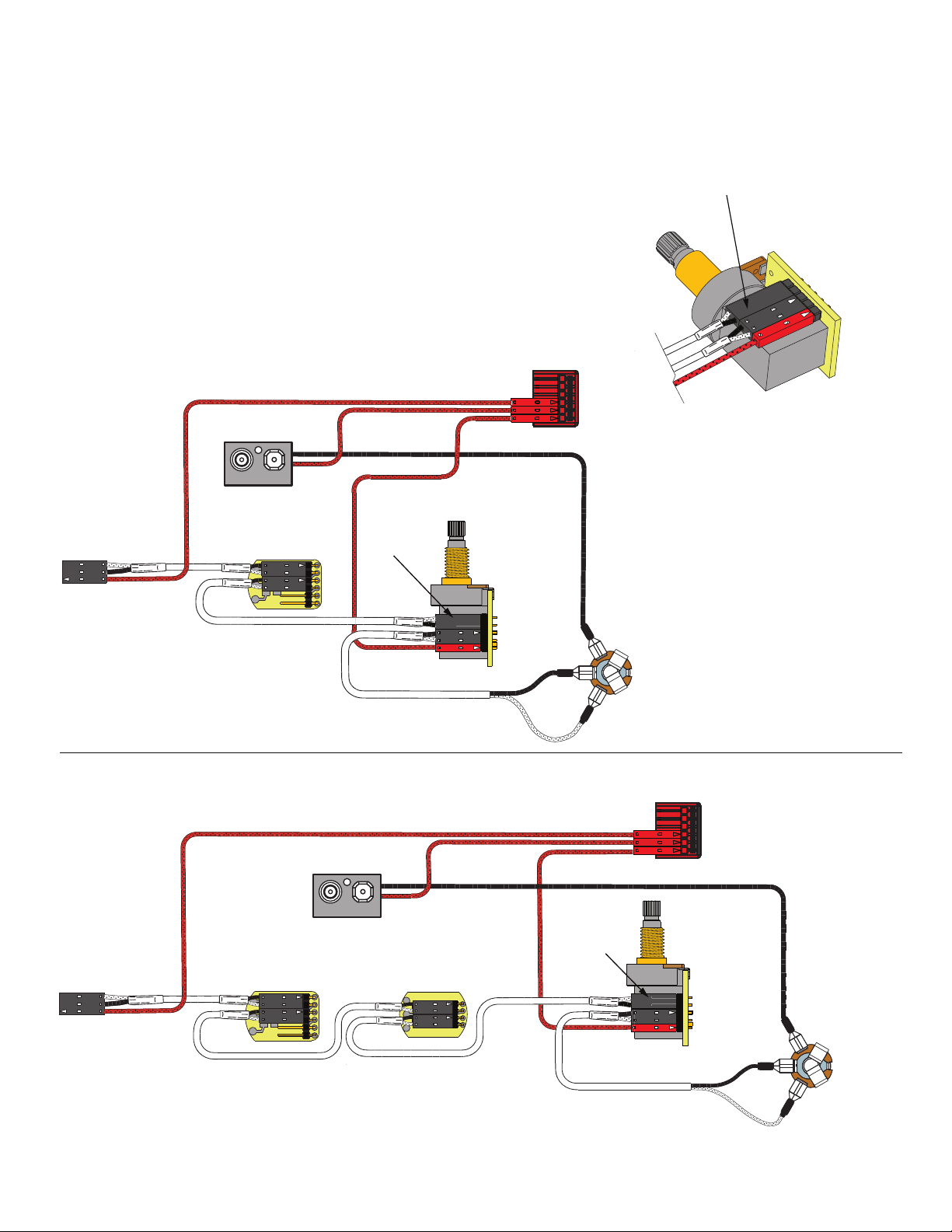
Diagram #3
One Pickup
One Volume
One Master Tone (Passive)
One AB Control
FROM PICKUP
VOLUME
MASTER
VOLUME
B122rH
VOLUME
- 9V +
OUTPUT CABLE
OUTPUT CABLE
MASTER
TONE
B124rH
TONE
RED
RED
RED
OUTPUT
R
S
T
BATTERY
BUSS
NOTE:
REVERSED
CONNECTOR
OUTPUT CABLE
BATTERY
NEG (-)
AB
OUTPUT
R
S
OUTPUT CABLE
AB (Afterburner) Page 2
T
Page 3

2 Pickup Guitars using a selection switch:
Diagrams #4 and #5 show the pickups connected to the B157 Pickup Buss.
To learn more about the B157 Pickup Buss, be sure to go to the EMG Website:
http://www.emgpickups.com. More diagrams are available at the EMG website.
The AB or any EMG Active Tone Control can follow the pickup buss
and then to the output jack.
Diagram #4
2 Pickups
Toggle Style Switch
Volume each Pickup (Volumes are independent)
AB Control
- 9V +
GROUND
NECK P/U
BATTERY
NEG (-)
NOTE:
REVERSED
CONNECTOR
AB
R
OUTPUT
BRIDGE P/U
GROUND
NECK P/U
OUTPUT
NECK PICKUP
BRIDGE PICKUP
- 9V +
RED
RED
RED
RED
OUTPUT CABLE
NK VOLUME
BR VOLUME
NOTE:
REVERSED
CONNECTOR
S
T
B122rH
VOLUME
B122rH
VOLUME
BATTERY
NEG (-)
AB
R
S
BRIDGE P/U
Diagram #5
2 Pickups
Toggle Style Switch
Volume each Pickup (Volumes are independent)
Master Tone (Passive)
AB Control
NECK PICKUP
BRIDGE PICKUP
AB (Afterburner) Page 3
RED
RED
OUTPUT CABLE
MASTER
TONE
B124rH
TONE
NK VOLUME
B122rH
VOLUME
BR VOLUME
B122rH
VOLUME
T
Page 4

3 Pickup Guitars using a selection switch:
Diagrams #6 and #7 show a typical installation with a Volume/Tone/AB in a
“daisy-chain” series wiring. The diagrams yield the same
results. The diagrams have been edited to show the input, output,
and power (9V+). The pickup inputs, battery, and “ring”contact to the jack
have been omitted for clarity.
All diagrams show the B161 5-Position switch buss. To learn more
about the B161 5-Position switch Buss, go to the EMG Website:
http://www.emgpickups.com.
Refer to Diagram #6
Volume / AB Control / Passive Tone Control
The AB Control and the Tone control can be in different
positions on the pickguard, but the wiring remains the same.
1) Plug a coax cable from the output switch to the Volume control.
2) Plug a coax cable from the Volume control to the Tone control.
3) Plug a coax cable from the Volume control to the input of the AB.
Be sure to reverse the connector on the input of the AB as shown.
4) Plug the output cable from the AB to the output jack.
5) Plug the Red wire from the AB to one of the supply pins on the
B161 Switch Buss.
Be sure the 3 shunts are installed on the bypass header of the
B161 switch or you won’t get any output from the guitar.
Refer to Diagram #7
Volume / VLPF Active Tone / AB Control
The AB Control and the VLPF Tone control can be in different
positions on the pickguard, but the wiring remains the same.
1) Plug a coax cable from the output switch to the Volume control.
2) Plug a coax cable from the Volume control to the input of the VLPF.
Be sure to reverse the connector on the input of the VLPF as shown.
3) Plug a coax cable from the output of the VLPF to the input of the AB Control.
4) Plug the output cable from the AB Control to the output jack.
5) Plug the Red wire from the AB to one of the supply pins on the
B161 Switch Buss.
Be sure the 3 shunts are installed on the bypass header of the
B161 switch or you won’t get any output from the guitar.
Refer to Diagram #8
Volume / SPC (Bridge Pickup only) / AB Control
Diagram #8 shows 2 active controls installed: The SPC and AB.
This installation is unique because it takes advantage of the
send/return feature of the B161 switch by using the SPC Control
only on the Bridge Pickup, while using the AB Control at the output of
the instrument.
1) Plug a coax cable from the switch output to the Volume control.
2) Plug a coax cable from the Volume control to the input of the AB.
Be sure to reverse the connector on the input of the AB as shown.
Send and Return to the SPC Control
3) Plug a coax cable from the Bridge Pickup Send pins on the Select switch
to the input of the SPC.
Be sure to reverse the connector on the input of the SPC as shown.
4) Plug a coax cable from the output of the SPC to the Bridge pickup
Return pins on the Select Switch.
Be sure to remove the blue shunt on the B161 switch for the bridge
pickup or the SPC Control will have no effect.
Plug the output cable from the AB to the output jack.
5) Plug the Red wires from both the SPC and AB to the extra 9V+
supply pins on the B161 Switch Buss.
Diagram #6
Volume Control
Tone (Passive)
AB Control
TO OUTPUT JACK
Diagram #7
Volume Control
Tone (Active VLPF)
AB Control
TO OUTPUT JACK
Diagram #8
Volume Control
Tone (Active VLPF)
AB Control
TO OUTPUT JACK
TONE CONTROL
(PASSIVE)
VLPF
ACTIVE TONE
NOTE:
REVERSED
CONNECTOR
AB CONTROL
AB CONTROL
RETURN
SEND
VOLUME CONTROL
NOTE:
REVERSED
CONNECTOR
VOLUME CONTROL
NOTE:
REVERSED
CONNECTOR
REMOVE
BLUE SHUNT
AB (Afterburner) Page 4
NOTE:
REVERSED
CONNECTOR
SPC
CONTROL
AB CONTROL
VOLUME CONTROL
NOTE:
REVERSED
CONNECTOR
 Loading...