

Page 1

7) SPECIAL NOTE:
The diagrams shown are for EMG-X Active Pickups.
All diagrams show the Red Wire coming from the pickups
connected to the battery. If you are installing EMG-HZ
Passive Pickups refer to their diagrams. The Red Wire of
the HZ Pickup is NOT for battery power, it is a coil wire.
4.500
3.985
R .125
TYP
1.500
PO BOX 4394
SANTA ROSA, CA
95402 USA
0230-0141A
P (707) 525-9941
F (707) 575-7046
EMGPICKUPS.COM
X-SERIES
.125 DIA. MOUNTING HOLES
MAXIMUM RECOMMEMDED STRING WIDTH 3.75"
.750
4.250
.880
INSTALLATION INFORMATION
EMG MODEL: 45-TW-X
SPECIFICATIONS: MODEL:
45-TW-X Single-Coil Dual-Coil
Logo Color* Copper
Magnet Type Alnico
Resonant Frequency (KHz) 3.50 2.50
Output Voltage (String) 1.00 4.00
Output Voltage (Strum) 3.00 8.50
Output Noise (60 Hz) -107 -109
Output Impedance (Kohm) 2.00 2.00
Current @9V (Microamps) 160
Battery Life (Hours) 1500
Maximum Supply (Volts DC) 27
Installation notes:
EMG-X Series Pickups are compatible with all EMG Active Pickups. They use the connector system for easy installation, avoiding the need to solder.
Older EMG Pickups may need to be soldered, while the newer systems can be easily connected and modified. The X-Series Active Tone Control (VLPF)
is compatible with older EMG Pickups and can be used in place of the passive tone control used with other EMG Active Pickups.
EMG accessories like the EXG, SPC or RPC Controls can be added to any EMG Pickup System without the need for an extra battery. When using a
selection switch, refer to the included B157 Pickup Buss Instructions for a detailed explanation of the Buss.
EMG-45-TW-X (SIDE VIEW)
C1
C2
C3
In Dual-coil mode, coils C1 and C2 are active.
In Single-coil mode, coils C2 andC3 are active.
IMPORTANT INSTALLATION NOTES:
1) Only one 9-Volt battery is required to power the pickups and any
accessories such as the SPC, RPC, EXG, AB, PA-2, and Pi-2.
Use an Alkaline or Lithium battery for longest life.
2) The Volume Control included with the EMG-X System is 25K Ohm.
This value is required for the system to work correctly.
3) A stereo output jack (12B) is included with the EMG-X Pickups;
it grounds the black battery wire to turn on the pickups when
the plug is inserted into the jack. If you are replacing passive
pickups, make sure to use the jack included. If your guitar has a
long panel jack (see Page 2, bottom), make sure it is a stereo
type, a Switchcraft 152B is recommended.
4) When installing any EMG-X Active Pickup, DO NOT connect the
bridge ground wire. This wire is usually soldered to a volume or
tone control casing and goes to the bridge. This wire grounds the
strings and uses them and your body as a shield against hum and
buzz. It also creates a shock hazard.
EMG Pickups are shielded internally and DO NOT require string
grounding. This greatly reduces the possibility of reverse
polarity shock from microphones and other equipment.
5) EMG-X Active Pickups have very little magnetism compared to
passive pickups. We recommend you adjust the pickups as
close to the strings as possible. Sustain and string movement
will not be inhibited by close adjustment.
6) If your installation is different from the diagrams in these
instructions or you need additional diagrams visit our website:
emgpickups.com for a complete listing of available diagrams.
7) SPECIAL NOTE:
The diagrams shown are for EMG-X Active Pickups.
All diagrams show the Red Wire coming from the pickups
connected to the battery. If you are installing EMG-HZ
Passive Pickups refer to their diagrams. The Red Wire of
the HZ Pickup is NOT for battery power, it is a coil wire.
Warranty
All EMG Pickups and accessories are warranted for a period of two years. This warranty does not cover failure due to improper installation, abuse or damage. If
upon examination the pickup is determined to be defective, a replacement will be made. Warranty replacement products are covered by this same warranty. This
warranty covers only those pickups and accessories sold by authorized EMG Dealers. This warranty is not transferable.
© 2010 Copyright EMG INC. All Rights Reserved.
Page 2
Installation Instructions:
EMG Models: EMG-45-TW-X
General Notes:
Every attempt has been made to make this a solderless installation.
There are some instances where this is not possible;
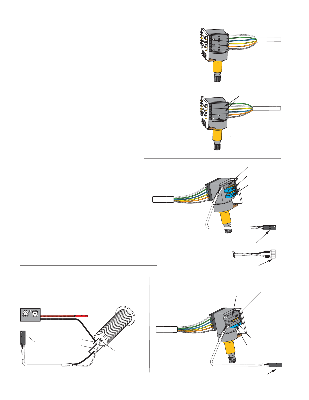
1) If your instrument uses the long panel output jack and you had passive pickups
you will need a new stereo output jack, the Switchcraft 152B is recommended.
Soldering to the new jack will be required, see diagram #5 below.
2) Some instruments may already have a battery holder installed and in that case
soldering may be required, see the diagram at the bottom of page 3.
3) Instruments with two pickups may need soldering to the selection
switch in some installations.
Using the 45-TW-X Push-Pull Pot
The Push-Pull Pot included with the EMG-45-TW-X allows you to choose between
two internal pickups, single-coil and dual-coil. The Push-Pull Pot has two seperate
sections described below.
Refer to diagrams #1 and #2
1) The push-pull pot has a switch section (DPDT) that lets you choose
between the single-coil sound and a dual-coil sound by pulling or pushing
the pot shaft up or down. You have the option of having the single-coil
sound in either the up or down position and the same for the dual-coil sound.
Diagrams #1 and #2 show how to connect the 45-TW-X pickup cable to choose
either option. Select the diagram that suits you and push the cable
connectors onto the single line 6 pin header.
Simply flip cable connectors 1 and 2 to change the wire order and this
will choose between the two options.
Connector 3 remains the same for either choice.
Refer to diagrams #3 and #4
2) The pot section (25KA) can be used either as a volume control
for the pickup or, it can be used as the master volume for the guitar.
Diagrams #3 and #4 show how to connect either opition.
Use the dual-line 10 pin header and push the cables on and
install the shunts as needed onto the labeled headers H1 thru H5.
Diagram #1
HUMBUCKING ON: DOWN POSITION
SINGLE COIL ON: UP POSITION
Diagram #2
SINGLE-COIL ON: DOWN POSITION
HUMBUCKING ON: UP POSITION
Diagram #3
PUSH / PULL POT USED AS
THE PICKUP VOLUME CONTROL
1
2
3
FLIP CONNECTORS 1 AND 2
AS SHOWN
1
2
3
WIRE ORDER:
WHITE
GREEN
BLUE
YELLOW
ORANGE
SHIELD
WIRE ORDER:
GREEN
WHITE
YELLOW
BLUE
ORANGE
SHIELD
PICKUP OUTPUT (H1)
SHUNT ON (H3)
SHUNT ON (H5)
Use diagram #3 if you have a single 45-TW-X installed in your instrument,
or have two or more pickups in your instrument and want to use the pot as the
volume control for the 45-TW-X Pickup.
Installing the shunts on positions H3 and H5 sends the pickup signal
to the wiper of the 25K Pot, and the output of the 25K Pot is at position H1.
Diagram #4 allows you to use the 25K Pot independently of the pickup output.
By taking the output of the pickup from position H4, the volume control is now
available to use as a master volume with H1 and H2 being the input and/or output
of the volume control. H1 and H2 positions are interchangeable.
Position H4, now the output of the pickup, would typically go to a selection switch
or a pan-pot. Don’t forget to install the shunt on H5.
Diagram #5
Soldering to the 152B Panel Jack:
If your instrument has a long Panel Jack like the one below
you will have to solder the output cable as shown.
Ground (Black) to the Sleeve
Signal (White) to the Tip
Battery Negative (Black) to the Ring
- 9V +
FROM TONE
OR VOLUME
RED to BATTERY BUSS
BATTERY
NEG (-)
RING
SLEEVE
TIP
TO TONE CONTROL OR
SELECTION SWITCH (B157 BUSS)
OR TO THE OUTPUT JACK IN SINGLE
PICKUP GUITARS WITH NO TONE
CONTROL
MASTER VOLUME CONTROL OUTPUT (H2)
MASTER VOLUME CONTROL INPUT (H1)
Diagram #4
PUSH / PULL POT USED AS
THE MASTER VOLUME CONTROL
PICKUP OUTPUT (H4)
SHUNT ON (H5)
45-TW-X INSTRUCTIONS Page 2
TO SELECTION SWITCH (B157 BUSS)
OR PAN-POT
Page 3
Installation (One Pickup Guitars):
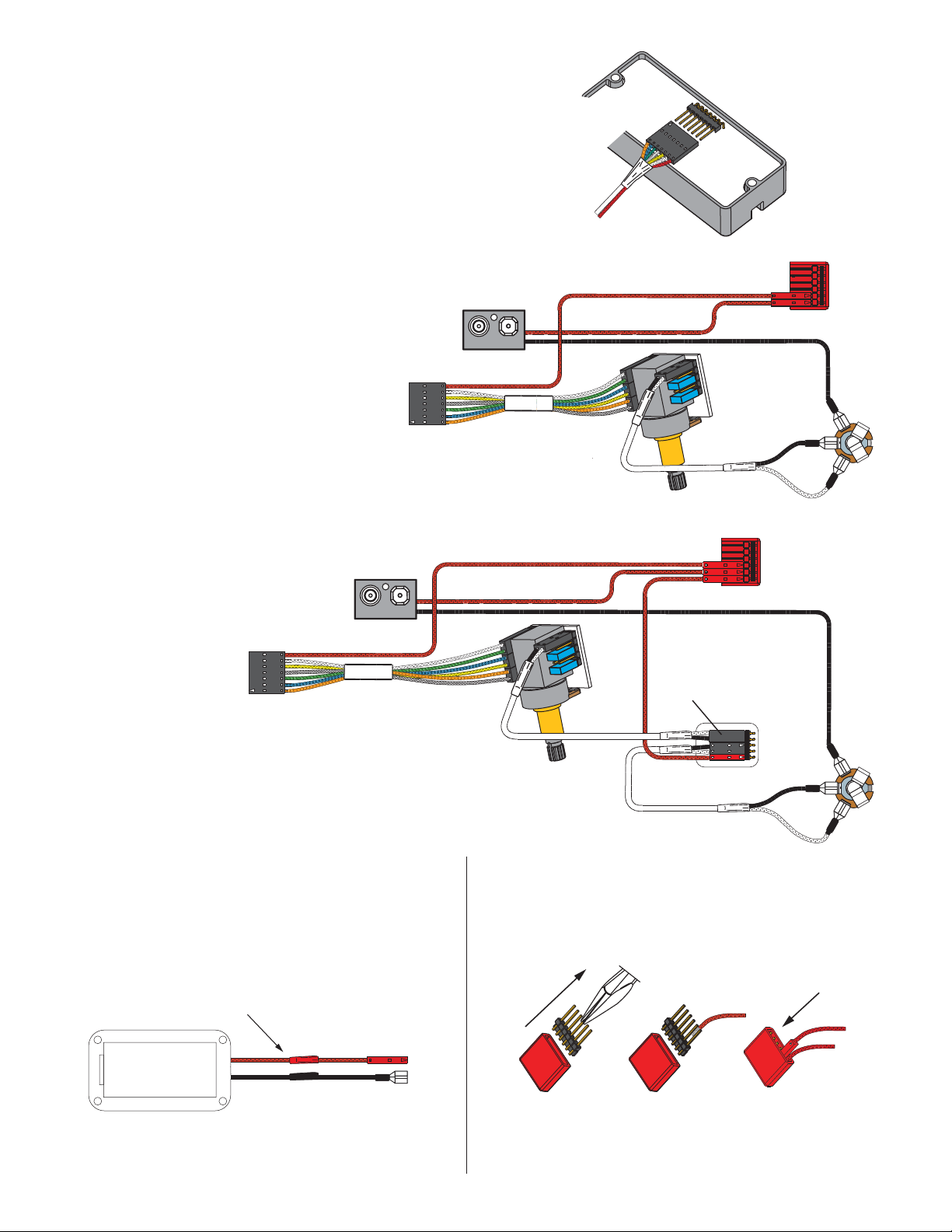
1) Plug the pickup cable onto the EMG Pickup header as shown
in diagram #6 and route the cable to the control cavity.
If the cable is too long, wind up the excess and keep it
under the pickup if possible
1 45-TW-X with a Master Volume only.
Refer to diagram #7.
2) Plug the Pickup cable onto the push-pull pot switch section using
the option chosen from diagram #1 or #2.
Plug the output cable onto the H1 position of the push-pull pot
section as shown in diagram #7 and be sure the shunts are
installed on header positions H3 and H5. No shunts on H2 and H4.
Skip to step 4.
1 45-TW-X with a Master Volume and VLPF Active Tone control
Refer to diagram #8.
3) Install the VLPF Active Tone included with the 45-TW-X Pickup.
Plug a coax cable from the push-pull pot to the VLPF Active
Tone Control. (Note the reversed connnector on pins 1 and 2).
Insert the output cable onto the Tone control as shown
(Pins 3 and 4).
4) Connect the output wires to the output jack by pushing
the connectors onto the jack as shown.
WHITE wire to the TIP (T) contact,
BLACK wire to the SLEEVE (S) contact
BLACK Battery Negative wire to the RING (R) contact.
5) Using the battery buss, insert the RED wire of the pickup,
the battery RED wire, and the RED wire from the VLPF onto
any of the pins. Extra pins can be used for EMG Accessories.
6) Put the battery in the insulating foam piece provided
and place it securely in the control cavity.
We suggest that you plug in the instrument and
test it before closing the control cavity.
Diagram #8
One 45-TW-X Pickup
One Volume
One Active Tone
- 9V +
Diagram #6
Insert the plug onto the 7 pin header
of the pickup as shown here.
Note the orientation arrow.
Diagram #7
One 45-TW-X Pickup
One Master Volume Control
No Tone Control
- 9V +
FROM 45-TW-X PICKUP
RED
RED
RED
RED
RED
VOLUME
CONTROL
OUTPUT CABLE
BATTERY
BUSS
BATTERY
BUSS
BATTERY
NEG (-)
OUTPUT
R
S
T
FROM 45-TW-X PICKUP
Diagram #9
If the instrument has a Battery Holder:
If your instrument has a 9 or 18 Volt battery holder you can still
use the EMG Connectors to supply power to the pickups.
Simply cut and strip the wires from the battery clip provided.
Twist the wires together and use the shrink tubing included
to cover the connections. Soldering the wires is the recommended.
Cover these connections with the
shrink tubing provided.
RED to BATTERY OR PICKUP BUSS
9/18 VOLT
BATTERY
HOLDER
BLACK to RING terminal
of the Output Jack
BATTERY
NEG (-)
VOLUME
CONTROL
NOTE:
REVERSED CONNECTOR
VLPF
OUTPUT CABLE
Diagram #10
Soldering to the battery buss:
If your instrument has an older EMG Pickup you can solder the
pickup RED wire to the buss. Simply use some needle nose pliers,
pull out the V+ header and solder the RED Wire from the pickup(s)
to any of the pins and then re-insert the header into the housing.
1
2
Solder the RED wire from the Battery Holder and/or
pickups and re-insert the Header into the insulation cover
3
OUTPUT
R
S
T
45-TW-X INSTRUCTIONS Page 3
Page 4
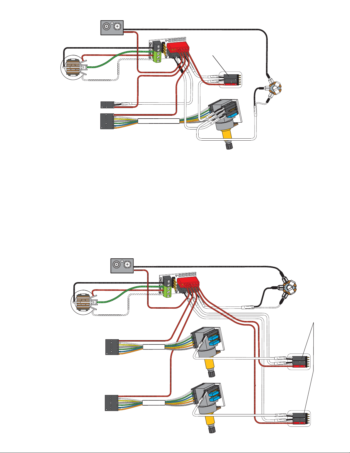
Diagram #11
2 Pickups (1 EMG + 1-45-TW-X)
Toggle Style Select Switch
Push-Pull Pot as Master Volume
with a Master Tone (VLPF)
- 9V +
GROUND
NECK P/U
OUTPUT
BRIDGE P/U
RED
RED
BATTERY
NEG (-)
NOTE:
REVERSED CONNECTOR
MASTER
TONE (VLPF)
OUTPUT
R
S
FROM NECK PICKUP
FROM 45-TW-X PICKUP
Refer to Diagram #11 Above:
1) Install the Pickups and route the cables to the control cavity keeping
any excess cable under the pickup.
2) Choose an up/down option from diagram #1 or #2 and plug the 45-TW-X
Pickup cable onto the push-pull pot.
3) Route a coax cable from the push/pull pot (H4) to the Pickup buss, Position 1.
Plug the pickup cable of the other EMG into Position 2 of the pickup buss.
4) Plug a coax cable from Position 3 of the Pickup Buss to the VLPF.
Plug a coax cable from the VLPF to the push/pull pot (H1)
5) Plug the output cable from the push/pull pot (H2) to the output jack and push
the connectors onto the T, S, and R terminals of the jack as shown.
6) Plug the RED Wires of the pickups onto the V+ Supply Buss (RED Shroud)
with the RED of the VLPF and the RED wire of the battery clip.
7) Strip the insulation from the switch wires and Insert them into the GREEN
and BLACK Terminal Blocks and tighten the screws with a small screwdriver.
Refer to the B157 Pickup buss instructions enclosed.
8) Put the battery in the insulating foam piece provided and place it securely in
the control cavity.
We suggest that you plug in the instrument and test it before closing the
control cavity.
T
RED
MASTER
VOLUME
OUTPUT CABLE
Refer to Diagram #12 Below:
1) Install the 45-TW-X Pickups and route the cables to the control cavity keeping
any excess cable under the pickup.
2) Choose an up/down option from diagram #1 or #2 and plug the 45-TW-X Pickup
cables onto the push-pull pots.
3) Route a coax cable from each of the push/pull pots (H1) to the VLPF Controls.
4) Plug a coax cable from the Bridge VLPF to the Pickup Buss (Position 1)
Plug a coax cable from the Neck VLPF to the Pickup Buss (Position 2)
5) Plug the output cable from the push/pull pot (H2) to the output jack and push
the connectors onto the T, S, and R terminals of the jack as shown.
6) Plug the RED Wires of the pickups onto the V+ Supply Buss (RED Shroud)
with the RED of the VLPF and the RED wire of the battery clip.
7) Strip the insulation from the switch wires and Insert them into the GREEN
and BLACK Terminal Blocks and tighten the screws with a small screwdriver.
Refer to the B157 Pickup buss instructions enclosed.
8) Put the battery in the insulating foam piece provided and place it securely in
the control cavity.
We suggest that you plug in the instrument and test it before closing the
control cavity.
Diagram #12
2 45-TW-X Pickups
2 Push-Pull Pots as Volume controls
(volumes are independent)
2 Active Tones (VLPF)
Toggle Style Switch
45-TW-X INSTRUCTIONS Page 4
- 9V +
GROUND
NECK P/U
OUTPUT
BRIDGE P/U
FROM 45-TW-X PICKUP
(NECK)
FROM 45-TW-X PICKUP
(BRIDGE)
RED
RED
RED
OUTPUT CABLE
NECK
VOLUME
BRIDGE
VOLUME
BATTERY
NEG (-)
OUTPUT
R
S
T
NOTE:
REVERSED
CONNECTORS
NECK TONE
(VLPF)
BRIDGE TONE
(VLPF)
 Loading...