

Page 1
READ AND SAVE THESE INSTRUCTIONS
Model Numbers
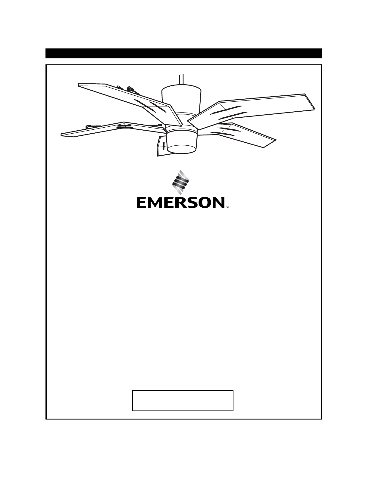
ORIGAMI
™
Part No. F40BP73490000 Form No. BP7349
U.L. Model No.: CF3000
Net Weight: 25.0 Lbs.
Damp Location
Ceiling Fan
Owner's Manual
CF3000BS00
Brushed Steel
CF3000ORB00
Oil Rubbed Bronze
Page 2
2
WARNING:
To avoid fire, shock, and serious personal injury, follow these instructions.
Safety Instructions
1. Read your owner’s manual carefully and keep it for future reference.
2. Before servicing or cleaning unit, switch power off at service panel and lock service panel disconnecting
means to prevent power from being switched on accidentally. When the service disconnecting means cannot
be locked, securely fasten a warning device, such as a tag, to the service panel.
3. Be careful of the fan and blades when cleaning, painting, or working near the fan. Always turn off the power to
the ceiling fan before servicing.
4. Do not put anything into the fan blades while they are turning.
5. Do not operate reversing switch until fan blades have come to a complete stop.
Additional Safety Instructions for Installation
1. To avoid possible shock, be sure electricity is turned off at the fuse box before wiring, and do not operate fan
without blades.
2. All wiring must be in accordance with the National Electrical Codes “ANSI/NFPA 70-1999” and Local Electrical
Codes. Use the National Electrical Code if Local Codes do not exist. The ceiling fan must be grounded as a precaution against possible electrical shock. Electrical installation should be made or approved by a licensed electrician.
3. The outlet box and joist must be securely mounted and capable of reliably supporting at least 50 pounds. Use
only U.L. outlet boxes listed as “Acceptable for Fan Support”, and use the mounting screws provided with the
outlet box. Most outlet boxes commonly used for support of light fixtures are not acceptable for fan support
and may need to be replaced. Consult a qualified electrician if in doubt.
4. The downrod furnished with the fan proves the minimum recommended floor to fan blade clearance for an
8 foot ceiling.
5. The fan must be mounted with the fan blades at least 7 feet from the floor to prevent accidental contact with the
fan blades.
6. Follow the recommended instructions for the proper method of wiring your ceiling fan. If you do not know
enough about electrical wiring, have your fan installed by a licensed electrician.
CAUTION: The halogen bulb operates at high internal pressure and high surface temperatures and could shatter
unexpectedly. The halogen bulb generates UV (ultraviolet) radiation that may cause skin and eye irritation with
prolonged exposure. To avoid risks of burns or other injury, assure power is off before attempting to install or
replace halogen bulb. Do not operate fan/light without lower glass in place.
7. This fan uses a halogen bulb. Do not touch the bulb with bare hands. Fingerprints may result in shorter bulb
life. Remove fingerprints with alcohol.
NOTE: This fan is suitable for use with solid-state speed controls.
WARNING: To reduce the risk of fire or electric shock, this fan should only be used with fan speed control
SW105, manufactured by Rhine Electric Co., Ltd.
WARNING: To avoid fire, shock or injury, do not use an Emerson or any other brand of control not specifically
approved for this fan.
WARNING: This product is designed to use only those parts supplied with this product and/or any accessories
designated specifically for use with this product by Emerson Electric Co. Substitution of parts or accessories not
designated for use with this product by Emerson Electric Co. could result in personal injury or property damage.
WARNING: To reduce the risk of personal injury, do not bend the blade flange when installing the blade flanges,
balancing the blades or cleaning the fan. Do not insert foreign objects in between rotating fan blades.
WARNING: To reduce the risk of electrical shock, this fan must be installed with an isolating wall
control/switch.
WARNING
!
DATE CODE:
The date code of this fan may be found on the box, stamped in ink on a white label.
You should record this data above and keep it in a safe place for future use.
THIS FAN IS SUITABLE FOR DAMP LOCATIONS SUCH AS
COVERED PORCHES, COVERED PATIOS, AND COVERED DECKS. . .
ANYWHERE THERE IS A ROOF OVERHEAD.
U.L. Model No.: CF3000
Page 3
Tools Needed for Assembly
One Phillips head screwdriver One wire stripper
One stepladder
MATERIALS
Wiring, outlet box and box connectors must be of type
required by the local code. The minimum wire would
be a 3-conductor (2-wire with ground) of the following
sizes:
Unpacking Instructions
For your convenience, check-off boxes are provided next to each step. As each step is
completed, place a check mark in the box. This will insure that all steps have been
completed and will be helpful in finding your place should you be interrupted.
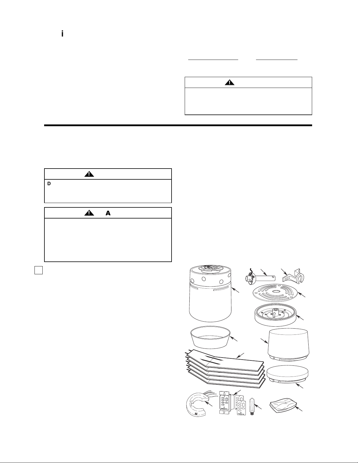
1. Open styrofoam unit containing fan. Remove top
half of styrofoam unit. Remove parts and check to
see that you have received the following parts:
NOTE: If you are uncertain of part description,
refer to exploded view illustration.
a. Fan motor and housing assembly
b. One ceiling cover
c. Five fan blade assemblies
d. One hanger ball/downrod assembly
e. One hanger bracket
f. One switch housing cover
g. One light kit assembly
h. One light kit glass
i. One decorative light cover
j. One SW105 receiver
k. One SW114 wall control/3 wall control covers
l. One 75-watt (max.) mini-candelabra
(E11) base bulb
m.One loose parts bag containing:
1. One setscrew
2. One setscrew wrench
3. Two 1-1/4” threaded studs
3
4. Two knurled knobs
5. Two lockwashers
6. Five wire connectors
7. One hairpin clip
8. One clevis pin
9. Twenty-one #10-24 x 15mm
flat head screws
10. Four #8-32 x 10mm pan head screws
11. Four #8-32 x 12mm pan head screws
12. One balancing kit
NOTE: Place the parts from the loose parts bags in a
small container to keep them from being lost. If any
parts are missing, contact your local retailer or
catalog outlet for replacement before proceeding.
Before assembling your ceiling fan, refer to section on
proper method of wiring your fan (page 7). If you feel
you do not have enough wiring knowledge or experience, have your fan installed by a licensed electrician.
WARNING
!
Do not install or use fan if any part is damaged or
missing. Call Toll-Free:
1-800-654-3545
This product is designed to use only those parts
supplied with this product and/or any accessories
designated specifically for use with this product by
Emerson Electric Co. Substitution of parts or
accessories not designated for use with this product
by Emerson Electric Co. could result in personal
injury or property damage.
WARNING
!
WARNING
!
This Manual Is Designed to Make it as Easy as Possible for You to
Assemble, Install, Operate and Maintain Your Ceiling Fan
Installed Wire Length Wire Size A.W.G.
Up to 50 ft. 14
50-100 ft. 12
U.L. Model No.: CF3000
d.
a.
h.
b.
c.
k.
H
I
H
I
L
IG
H
T
M
E
D
M
E
D
L
O
W
L
O
W
R
E
V
R
E
V
F
A
N
O
F
F
j.
e.
l.
f.
g.
i.
m.
Page 4
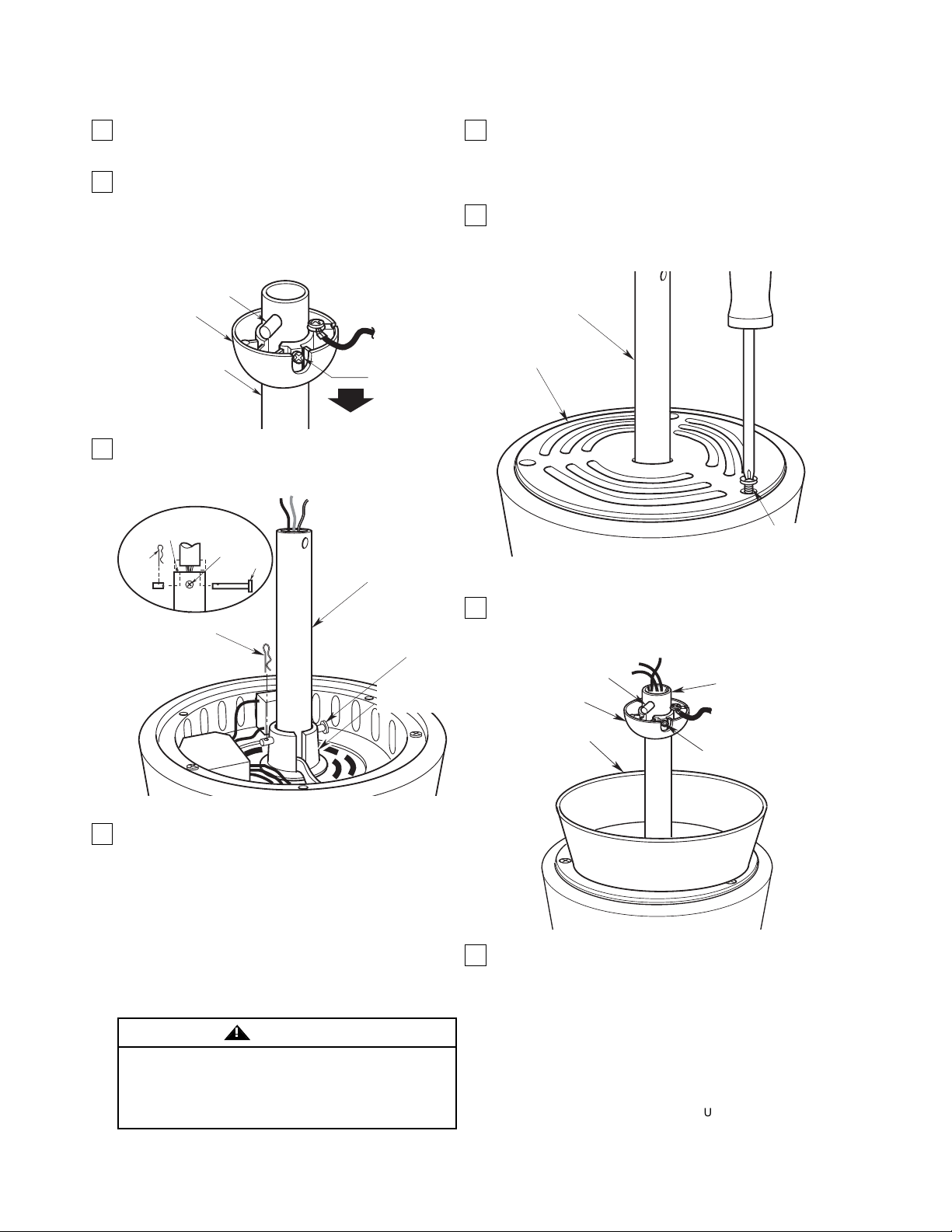
1. Remove the fan motor and housing assembly from
the styrofoam packaging and position it so that the
top of the motor is facing you.
2. Remove the hanger ball from the downrod by
loosening the setscrew in the hanger ball until the
ball falls freely down the downrod (Figure 1).
Remove the pin from the downrod, then remove
the hanger ball. Retain the pin and hanger ball for
reinstallation in step 8.
3. Separate, untwist and unkink the three motor leads.
Route the motor leads through the downrod and
seat the downrod in the motor coupling (Figure 2).
4. Align the clevis pin holes in the downrod with the
holes in the motor coupling. Install the clevis pin
and secure with the hairpin clip (Figure 2). (Pin and
clip are supplied in loose parts bag.) The clevis pin
must go through the holes in the motor coupling
and the holes in the downrod. Push the straight leg
of the hairpin clip through the hole near the end of
the clevis pin until the curved portion of the hairpin
clip snaps around the clevis pin. The hairpin clip
must be properly installed to prevent the clevis pin
from working loose. Pull the downrod to make sure
the clevis pin is properly installed.
5. Install the setscrew (supplied) in the motor coupling
(Figure 2). While pulling up on the downrod, tighten
the setscrew using the setscrew wrench (supplied).
NOTE: The setscrew must be properly installed as
described above, or fan wobble could result.
6. Slide the switch housing cover over the downrod
and position the cover onto the upper housing.
Install the three #8-32 x 10mm pan head screws
(supplied) (Figure 3).
7. Position the ceiling cover over the downrod. Be
sure the cover is oriented correctly, with the large
opening at the top (Figure 4).
8. Reinstall the hanger ball on the downrod (Figure 4)
as follows. Route the motor leads through the
hanger ball and slide the hanger ball over the
downrod. Install the pin through the holes at the top
of the downrod and slide the hanger ball up the
downrod, aligning the ball so the pin in captured in
the groove in the top of the hanger ball. Pull the
hanger ball up tight against the pin and securely
tighten the setscrew in the hanger ball. A loose
setscrew could create fan wobble.
4
How to Put Your Ceiling Fan Together
Figure 1
Figure 3
Figure 2
Figure 4
It is critical that the clevis pin in the motor coupling
is properly installed and the setscrew is securely
tightened. Failure to verify that the pin and setscrew
are properly installed (as shown in Figure 2) could
result in the fan falling.
WARNING
!
U.L. Model No.: CF3000
HAIRPIN
CLIP
HANGER
BALL
MOTOR
COUPLING
DOWNROD
SETSCREW
HAIRPIN
CLIP
PIN
SETSCREW
CLEVIS PIN
DOWNROD
MOTOR
COUPLING
DOWNROD
SWITCH
HOUSING COVER
CLEVIS
PIN
HANGER BALL
PIN
#8-32 x 10mm PAN
HEAD SCREWS (3)
DOWNROD
CEILING COVER
SETSCREW
Page 5
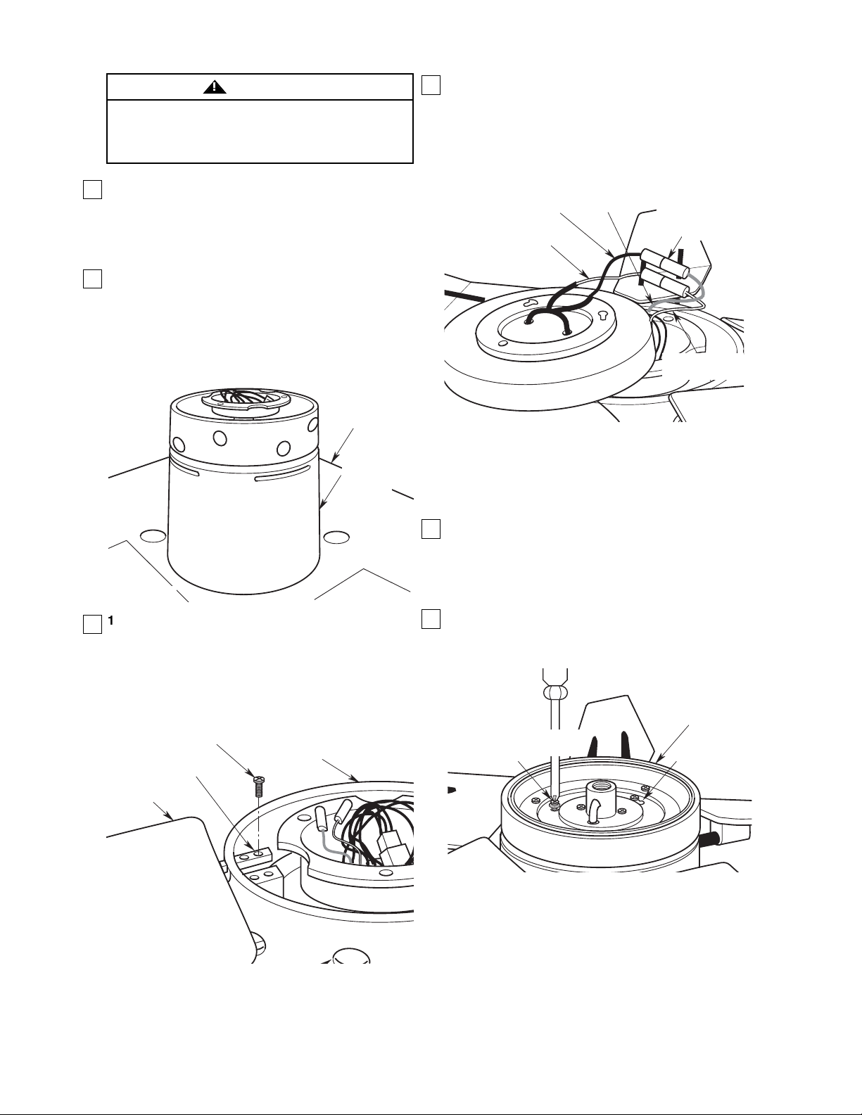
9. The fan comes with blue, black and white leads
that are 80-inches long. Before installing the fan,
measure up approximately 6 to 9-inches above top
of hanger ball/downrod assembly. Cut off excess
leads and strip back insulation 1/2-inch from end
of leads.
10. Position the bottom styrofoam section on a flat
surface exposing the large center hole for fan
motor placement. Place the partially assembled
fan motor hosing into the hole so that the bottom
of the motor is facing up (Figure 5). the styrofoam
section will hold the assembly while you perform
the following steps.
5
Figure 5
Figure 6
G
Figure 7
It is critical that the pin in the hanger ball is properly
installed and the setscrews securely tightened.
Failure to verify that the pin and setscrews are
properly installed could result in the fan falling.
WARNING
!
11. Position the two rods of the preassembled fan
blade into the two holes of the housing center
band. Install the four #10-24 x 15mm flat head
screws (2 pre rod, 4 per blade assembly)
(supplied) securing the fan blade to the housing
(Figure 6). Install the remaining four fan blades
using the same procedure.
12. Connect the switch housing blue wire single-pin
connector to the black wire single-pin connector
from the light kit assembly; connect the switch
housing white wire single-pin connector to the
white wire single-pin connector from the light kit
assembly (Figure 7). Be sure all wire connectors
are fully engaged.
CAUTION: Before installing and tightening the
screws, be sure there are no wires pinched
between the switch housing and the light kit
assembly.
13. Make sure all wires and single-pin connectors are
inside the switch housing, then position the light
kit assembly on the switch housing so that the
pan head screws protrude through the keyhole
slots in the light kit assembly. Turn the light kit
assembly clockwise to engage the slots.
14. Place the three #8-32 x 12mm pan head screws
and lockwashers (supplied) to secure the light kit
assembly to the switch housing (Figure 8).
Figure 8
SWITCH HOUSING
WHITE WIRE
U.L. Model No.: CF3000
STYROFOAM
FAN MOTOR
HOUSING
#10-24 x 15mm FLAT HEAD
SCREWS (2 per blade)
PREASSEMBLED FAN
ROD (2 per blade)
FAN BLADE (5)
HOUSING CENTER
BAND
LIGHT KIT
BLACK WIRE
LIGHT KIT
WHITE WIRE
SWITCH HOUSING
BLUE WIRE
SINGLE-PIN
CONNECTORS
ENGAGED
SWITCH HOUSIN
WHITE WIRE
#8-32 x 12mm PAN HEAD
SCREW & LOCKWASHER (3)
LIGHT KIT
ASSEMBLY
KEYHOLE
SLOT (2)
Page 6
6
Electrical Requirements
If your fan is to replace an existing ceiling light fixture,
turn electricity off at the main fuse box at this time and
remove the existing light fixture.
Your new ceiling fan will require a grounded electrical
supply line of 120 volts AC, 60 Hz, 15 amp circuit.
The outlet box must be securely anchored and
capable of withstanding a load of at least 50 pounds.
To reduce the risk of fire, electric shock, or personal
injury, mount fan to outlet box marked “Acceptable
for Fan Support”, and use screws supplied with
outlet box. Most outlet boxescommonly used for
support of light fixtures are not acceptable for fan
support and may need to be replaced. Consult a
qualified electrician if in doubt.
WARNING
!
Turning off wall switch is not sufficient. To avoid
possible electrical shock, be sure electricity is turned
off at the main fuse box before wiring. All wiring must
be in accordance with National and Local codes and
the ceiling fan must be properly grounded as a
precaution against possible electrical shock.
WARNING
!
How to Hang
Your Ceiling Fan
Figure 9
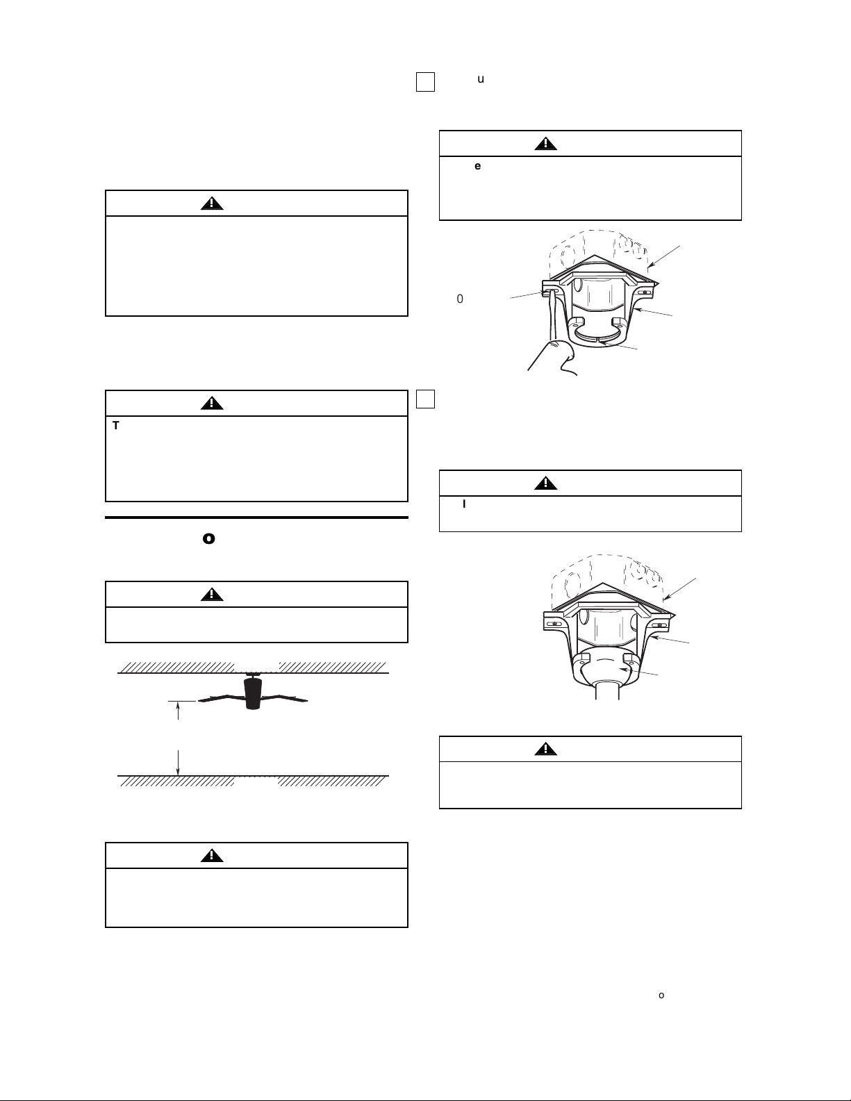
The fan must be hung with at least 7' of clearance
from floor to blades (Figure 9).
WARNING
!
TWO SCREWS
SUPPLIED WITH
OUTLET BOX
HANGER
BRACKET
TAB
OUTLET
BOX
Figure 10
2. Carefully lift the fan and seat the hanger ball/down-
rod assembly on the hanger bracket that was just
attached to the outlet box (Figure 11). Be sure the
groove in the ball is lined up with the tab on the
hanger bracket (Figure 10).
The outlet box and joist must be securely mounted
and capable of supporting at least 50 lbs. Use only a
U.L. outlet box listed as “Acceptable for Fan
Support”.
WARNING
!
Failure to seat tab in groove could cause damage to
electrical wires and possible shock or fire hazard.
WARNING
!
Hanger bracket must seat firmly against outlet box. If
the outlet box is recessed, remove wall board until
bracket contacts box. If bracket and/or outlet box are
not securely attached, the fan could wobble or fall.
WARNING
!
1. Securely attach the hanger bracket to the outlet
box using the two screws supplied with the outlet
box. (Figure 10.)
Figure 11
To avoid possible fire or shock, do not pinch wires
between the hanger ball/downrod assembly and
hanger bracket.
WARNING
!
U.L. Model No.: CF3000
CEILING
AT LEAST
7'
FLOOR
NOTE: CEILING COVER,
SUPPLY WIRES AND
FAN WIRES OMITTED
FOR CLARITY.
HANGER BALL/
DOWNROD
ASSEMBLY
OUTLET
BOX
HANGER
BRACKET
Page 7
7
Turning off wall switch is not sufficient. To avoid
possible electrical shock, be sure electricity is
turned off at the main fuse or circuit breaker box
before wiring. All wiring must be in accordance with
National and Local codes and the ceiling fan must be
properly grounded as a precaution against possible
electrical shock.
WARNING
!
Figure 12
If you feel that you do not have enough electrical
wiring knowledge or experience, have your fan
installed by a licensed electrician.
CAUTION: To reduce the risk of electrical shock,
disconnect the electrical supply circuit before
installing the fan and light kit or receiver.
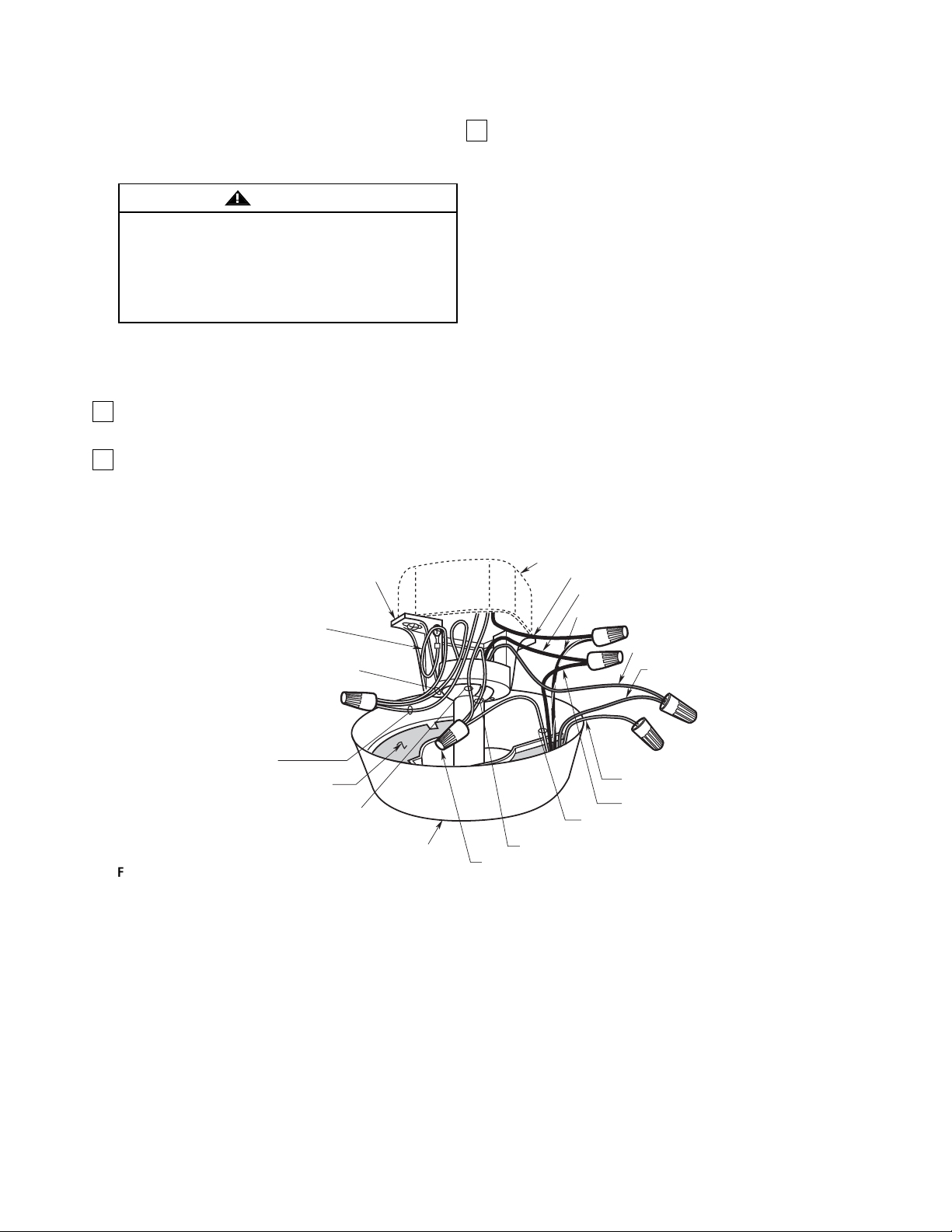
1. Pull the wire leads, coming from the end of the
downrod, and the supply wires through the open
side of the hanger bracket. (Figure 12).
2. Position the SW105 Receiver (supplied) in the ceil-
ing cover so that the flat side of the receiver faces
up and the open portion of the receiver is to the
right, as shown in Figure 12.
3. Using wire connectors (supplied), make wiring con-
nections as follows (Figure 12 and 13):
a. Connect the white fan wire and the white supply
wire to the white receiver wire (AC IN/
MOTOR N).
b. Connect the black fan wire to the black receiver
wire (TO MOTOR L).
c. Connect the black supply wire to the black/white
receiver wire (AC IN L).
d. Cut off the ends of the blue and yellow receiver
wires and strip back insulation 1/2-inch from the
ends of the wires.
e. Connect the blue fan wire to the blue receiver
wire (BOTTOM LIGHT).
f. Connect the green ground wires from the hang-
er bracket and the hanger ball to the supply
ground wire (bare or green).
NOTE: Do not use capped yellow wire.
How to Wire Your Ceiling Fan
U.L. Model No.: CF3000
HANGER BRACKET
HANGER BRACKET
GROUND WIRE
(GREEN)
HANGER BALL
GROUND WIRE
(GREEN)
OUTLET BOX
BLACK SUPPLY WIRE
BLACK FAN WIRE
BLACK/WHITE RECEIVER WIRE
BLUE FAN WIRE
BLUE RECEIVER
WIRE
SUPPLY GROUND
WIRE (GREEN OR
BARE)
RECEIVER
WHITE SUPPLY
WIRE
CEILING COVER
OPEN
PORTION OF
RECEIVER
HERE
WHITE FAN WIRE
WIRE CONNECTOR
YELLOW RECEIVER
WIRE DO NOT USE
BLACK RECEIVER WIRE
WHITE RECEIVER WIRE
Page 8
WHITE RECEIVER WIRE
8
Figure 14
Check to see that all connections are tight, including
ground, and that no bare wire is visible at the wire
connectors, except for the ground wire. Do not operate fan until blades are in place. Noise and fan damage could result.
WARNING
!
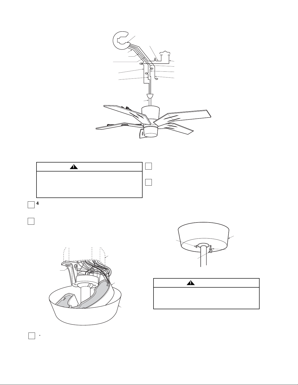
4. After connections have been made, separate the
white and green wires from the black, blue and
yellow wires.
5. Carefully turn the wires upward and insert them up
through the open side of the hanger bracket and
into the outlet box. Push the green and white wires
into one side of the outlet box; push the black, blue
and yellow wires into the other side of the outlet
box.
Figure 13
To avoid possible fire or shock, make sure that the
electrical wires are completely inside the outlet box
and not pinched between the ceiling cover and the
ceiling.
WARNING
!
6. Screw the two 1-1/4” threaded studs (supplied)
into the tapped holes in the hanger bracket
(Figure 15).
7. Lift the ceiling cover up to the threaded studs and
turn until studs protrude through the holes in the
ceiling cover (Figure 15).
8. Secure the ceiling cover in place by sliding
lockwashers (supplied) over the threaded studs and
installing the two knurled knobs (supplied).
(Figure 15.) Tighten the knurled knobs securely until
the ceiling cover fits snugly against the ceiling and the
hole in the ceiling cover is clear of the downrod. Your
fan is now wired to be turned on and off from the fan
switch.
Figure 15
U.L. Model No.: CF3000
BLACK RECEIVER WIRE
BLACK/WHITE
RECEIVER WIRE
WHITE FAN WIRE
BLACK FAN WIRE
SW105 RECEIVER
BLACK
SUPPLY
WIRE
DOWNROD
TO
110V
SUPPLY
WHITE SUPPLY
WIRE
BLUE RECEIVER WIRE
BLUE FAN WIRE
YELLOW RECEIVER WIRE
DO NOT USE
OUTLET BOX
HANGER
BRACKET
RECEIVER
CEILING
COVER
1-1/4"
THREADED
STUD
KNURLED KNOB
CEILING COVER
LOCKWASHER
Page 9
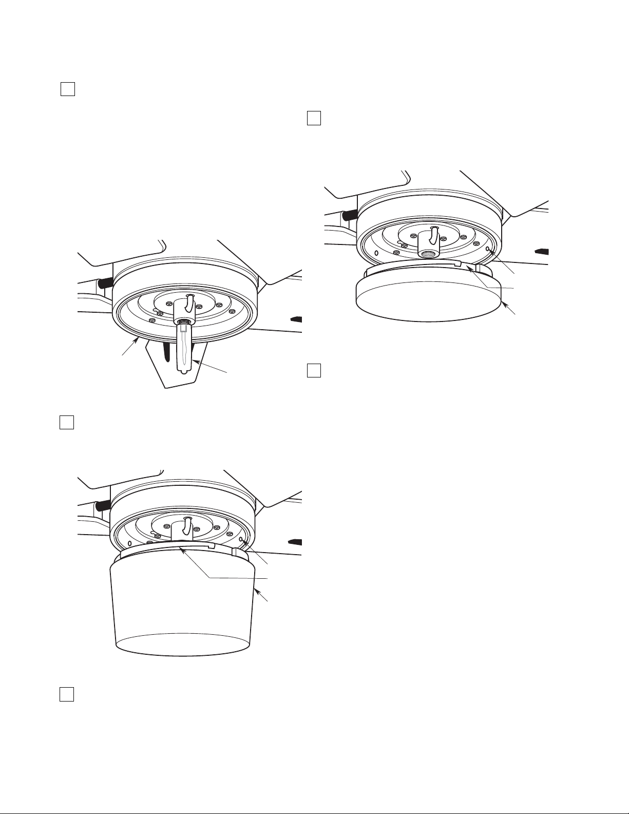
2. Place the glass onto the light kit assembly aligning
the three flat areas on the top flange of the glass
with the three pins on the inside of the assembly
(Figure 17). Then turn the glass clockwise until it
stops turning.
3. Your ceiling fan is now installed and wire to be
controlled by your remove control system.
9
Figure 16
Figure 17
1. Screw the 75-watt (maximum) mini-candelabra
(E11) base bulb (supplied) into the light kit socket
(Figure 16). Do not touch the glass bulb; use the
porcelain base to screw in the bulb, or wear
gloves.
CAUTION: To avoid risk of burns or other injury,
assure power is off before attempting to install or
replace the 75-watt (max.) mini-candelabra (E11)
base bulb.
CAUTION: To not touch 75-watt (max.) minicandelabra (E11) base bulb with bare hands.
Fingerprints may result in shorter bulb life.
Remove fingerprints with alcohol.
Light Kit Installation
1. Place the switch cover onto the light kit assembly
aligning the three flat areas on the top flange of the
switch cover with the three pins on the inside of
the assembly (Figure 18). Then turn the switch
cover clockwise until it stops turning.
2. Your ceiling fan is now installed and wire to be
controlled by your remove control system.
Figure 18
If no light kit is desired, continue with switch
cover installation.
Switch Cover Installation
U.L. Model No.: CF3000
LIGHT KIT
ASSEMBLY
75-WATT (max.)
MINI-CANDELABRA
(E11) BASE BULB
PIN (3)
TOP
FLANGE
SWITCH
COVER
PIN (3)
TOP
FLANGE
GLASS
Page 10
10
Setting Operating
Frequency of Wall Control
and Receiver
(Figure 19)
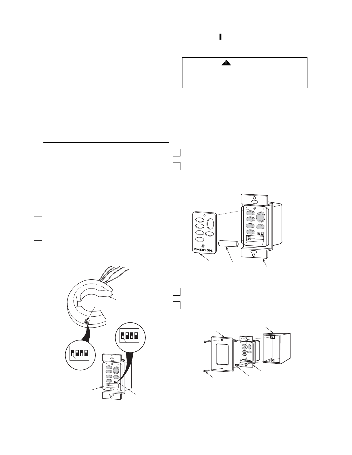
Your wall control and receiver have code switches
which must be set in one of 16 possible code combinations. The four levers (numbered 1, 2, 3, and 4) on
the switches are factory-set in the ON (up) position.
Change the switch settings as follows:
1. Slide the four switch levers in the wall control to
your choice of ON (up) or down positions. Use a
ball-point pen or small screwdriver and slide the
levers firmly up or down.
2. In the receiver, slide the four switch levers to the
same positions as set in the wall control. Make
sure the levers on both switches are in the same
positions, otherwise the fan will not operate.
Figure 19
The SW114 wall control transmits the command
signals via radio waves to the SW105 receiver
installed in the ceiling fan ceiling cover. The
SW105 receiver is required for the SW114 wall
control to function. Power for the SW114 wall
control comes from the 12V battery, located in the
wall control.
Replacement 12V batteries recommended are
Duracell MN21 and Eveready A23.
1. Install the 12V battery (supplied) into the wall
control (Figure 20).
2. The SW114 wall control is supplied with a white,
ivory or almond color cover. Choose the style that
best suits your needs and snap the cover onto the
wall control (Figure 20).
Figure 20
Turning off wall switch is not sufficient. To avoid
possible electrical shock, be sure electricity is
turned off at the main fuse or circuit breaker box.
WARNING
!
Installation
of Wall Control
3. Install the wall control onto the outlet box using the
supplied screws (Figure 21).
4. Install decorator wall plate (not included) using the
two screws provided with wall plate (Figure 21).
Figure 21
Ceiling Fan Procedures
General
Your Emerson Ceiling Fan/Light Wall Control consists
of a wall mount transmitter. The SW114 transmitter
works in conjunction with the SW105 Receiver
(purchased separately). The receiver is mounted
under the fan ceiling cover. The wall control is
designed to separately control your ceiling fan speed,
direction, uplight and downlight intensity.
Code switches in the wall control and receiver may be
set in 16 different positions. If your fan and light go on
and off without using your control, you may be getting
interference from other transmitters such as garage
door openers, car alarms or security systems.
To remedy this situation, simply change the combination code in your wall control and receiver.
U.L. Model No.: CF3000
WALL
CONTROL
COVER
HI
HI
MED
MED
LOW
LOW
FAN OFF
12V BATTERY
LIGHT
R
E
V
R
E
V
SW114 WALL
CONTROL
ON
1
234
RECEIVER SWITCH
LEVERS
SW114 WALL
CONTROL
CODE
SWITCH
MED
LOW
FA
N
HI
HI
MED
LOW
O
F
F
SW105
RECEIVER
ON
1
WALL CONTROL
LEVERS
L
IG
H
T
REV
REV
234
CODE
SWITCH
DECORATIVE WALL
PLATE (Not Included)
OUTLET
BOX
H
I
L
IG
H
T
M
E
D
L
O
W
R
E
V
F
A
N
O
F
F
SW114 WALL
CONTROL
WALL PLATE
SCREW (2)
WALL CONTROL
SCREW (2)
Page 11
11
Figure 22
Trouble Shooting
Wall Control
Fan/Light Fails to Operate
• Check that the wall switch for the ceiling fan is in the “ON”
position.
• Check that the battery is good (red indicator light should
light when any button is pressed).
• Check that the receiver is wired properly.
• Check that both transmitter and receiver code switches
are set in the same position.
Operating Your Ceiling Fan
IMPORTANT
Fan installation must be completed, including the
installation of the fan blades, before testing of the
wall control.
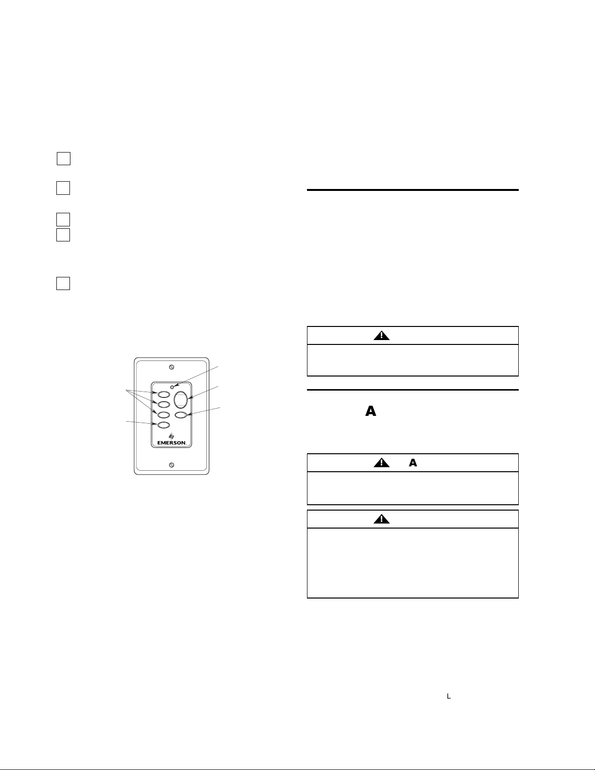
Your SW114 Fan/Light Wall Control (Figure 22) has
full control of your fan, lights, and airflow direction.
1. To set the desired fan speed, push the HI, MED, or
LOW buttons to operate your fan on high, medium
or low speed (See Figure 22).
2. To reverse the direction the fan is turning, press
the REV button. The direction the fan turns will
change each time the REV button is pressed.
3. To turn your fan off, press the FAN OFF button.
4. To set the level of light brightness, press and hold
the LIGHT button. The light brightness will continue
to increase then decrease while the button is held
down. When the light is at the desired brightness,
release the button.
5. To turn the light on or off, press and release the
LIGHT button. The light will turn on at the light level
previously set (See Step 4).
Red indicator light turns on when any button is
pressed. If the light does not come on, replace the
battery.
Maintenance
IMPORTANT CARE INSTRUCTIONS
for your Ceiling Fan
Periodic cleaning of your new ceiling fan is the only
maintenance that is needed.
When cleaning, use only a soft brush or lint free cloth
to avoid scratching the finish.
Abrasive cleaning agents are not required and should
be avoided to prevent damage to finish.
Do not use water when cleaning your ceiling fan. It
could damage the motor or the blades and create the
possibility of an electrical shock.
WARNING
!
Accessories
1. Downrod Extension Kits (see store or catalog).
2. Ceiling Fan Controls (see store or catalog).
This product is designed to use only those parts
supplied with this product and/or any accessories
designated specifically for use with this product by
Emerson Electric Co. Substitution of parts or
accessories not designated for use with this product
by Emerson Electric Co. could result in personal
injury or property damage.
The use of any other control not specifically
approved for this fan could result in fire, shock and
personal injury.
WARNING
!
WARNING
!
U.L. Model No.: CF3000
FAN
SPEED
BUTTONS
FAN OFF
BUTTON
FAN OFF
HI
LIGHT
MED
LOW
REV
RED
INDICATOR
LIGHT
LIGHT
BUTTON
AIRFLOW
DIRECTION
BUTTON
Page 12
12
INSTRUCTION TO THE USER (if device contains a digital device)
This equipment has been tested and found to comply with the limits for a class B digital device, pursuant to
part 15 of the FCC Rules. These limits are designed to provide reasonable protection against harmful interference in a residential installation. This equipment generates, uses and can radiate radio frequency energy and
if no installed and used in accordance with the instructions, may cause harmful interference to radio communications. However, there is not guarantee that interference will not occur in a particular installation. If this equipment does cause harmful interference to radio or television reception, which can be determined by turning the
equipment off and on, the user is encouraged to try to correct the interference by one or more of the following
measures:
• Reorient or relocate the receiving antenna.
• Increase the separation between the equipment and receiver.
• Connect the equipment into an outlet on a circuit different from that to which the receiver is connected.
• Consult the dealer or an experienced radio/TV technician for help.
This equipment has been certified to comply with the limits for a class B computing device, pursuant to FCC
Rules. In order to maintain compliance with FCC regulations, shielded cables must be used with this equipment. Operation with non-approved equipment or unshielded cables is likely to result in interference to radio
and TV reception. The user is cautioned that changes and modifications made to the equipment without the
approval of manufacturer could void the user’s authority to operate this equipment.
This Class B digital apparatus meets all requirements of the Canadian Interference-Causing Equipment
Regulations.
U.L. Model No.: CF3000
Page 13
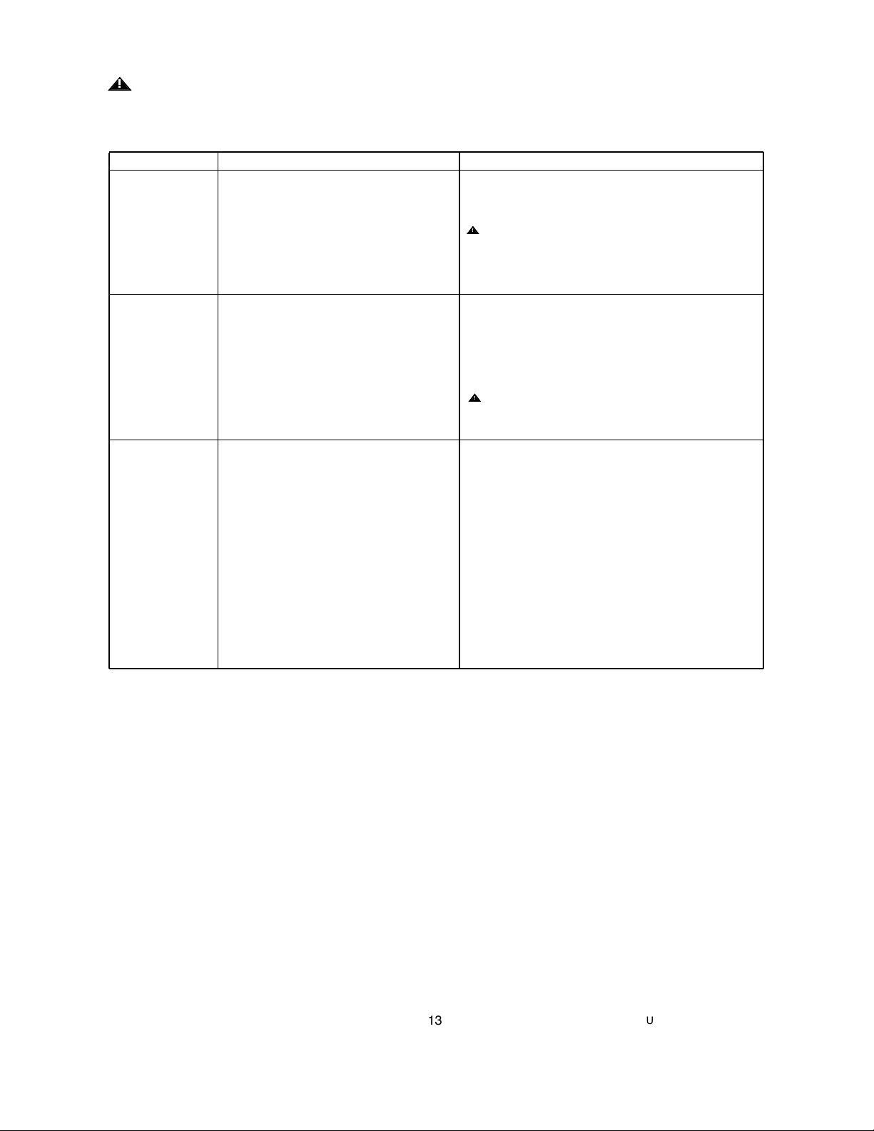
Trouble Shooting
TROUBLE PROBABLE CAUSE SUGGESTED REMEDY
1. Fan will not start. 1. Fuse or circuit breaker blown. 1. Check main and branch circuit fuses or circuit breakers.
2. Loose power line connections to the fan, or loose 2. Check line power connections to fan and switch wire
switch wire connections in the switch housing. connections in the switch housing.
WARNING: Make sure main power is turned off.
3. Fan/Light Wall Control is OFF. 3. Turn ON Fan/Light Wall Control.
4. Code switches in wall control/receiver are 4. Check that both code switches are set in the same
not set in the same position. positions.
2. Fan sounds 1. Blades not attached to fan. 1. Attach blades to fan before operating.
noisy.
2. Screws securing fan blades to motor 2. Check to make sure the screws which attach the fan blades
are loose. to the motor are tight.
3. Wire connectors inside switch housing rattling. 3. Check to make sure wire connectors in switch housing are
not rattling against each other or against the interior wall of
the switch housing.
WARNING: Make sure main power is turned off.
4. Loose screws in motor housing. 4. Check to make sure all screws in motor housing are snug
(not over-tight)
3. Fan wobbles 1. Setscrew in motor coupling is not tightened 1. Raise coupling cover and tighten setscrew securely.
excessively. securely.
2. Setscrew in the hanger ball/downrod assembly 2. Tighten the setscrew in the hanger ball/downrod assembly.
is loose.
3. Screws securing fan blade to 3. Check to be sure screws which attach the fan blade
motor are loose. to the motor are tight.
4. Fan blades are not seated properly. 4. Check to be sure the fan blade flanges seat firmly and
uniformly to the surface of the motor. If blades are seated
incorrectly, loosen the blade screws and retighten
according to Step 11 and Figure 6.
5. Hanger bracket and/or ceiling outlet box is 5. Tighten the hanger bracket screws to the outlet box, and/or
not securely fastened secure outlet box.
6. Fan blades out of balance. 6. Interchanging an adjacent (side-by-side) blade pair can
redistribute the weight and result in smoother operation.
Or use supplied balancing kit to balance blades.
WARNING: FOR YOUR OWN SAFETY TURN OFF POWER AT FUSE BOX OR CIRCUIT BREAKER
BEFORE TROUBLE SHOOTING YOUR FAN.
!
!
!
13
U.L. Model No.: CF3000
Page 14
14
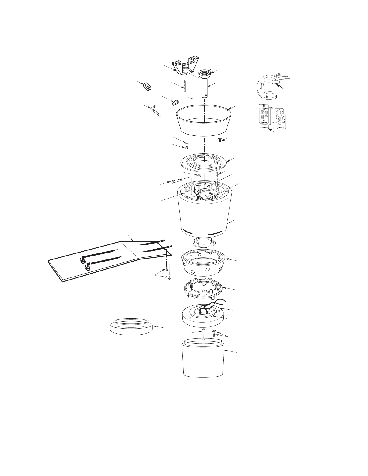
Repair Parts
6
1
11
10
4
19
7
8
H
I
H
I
M
E
D
M
E
D
L
O
W
L
O
W
F
A
N
O
F
F
R
E
V
R
E
V
L
I
G
H
T
3
2
16
17
13
5
18
21
30
12
29
22
20
27
14
25
26
28
9
15
23
24
31
U.L. Model No.: CF3000
Page 15
15
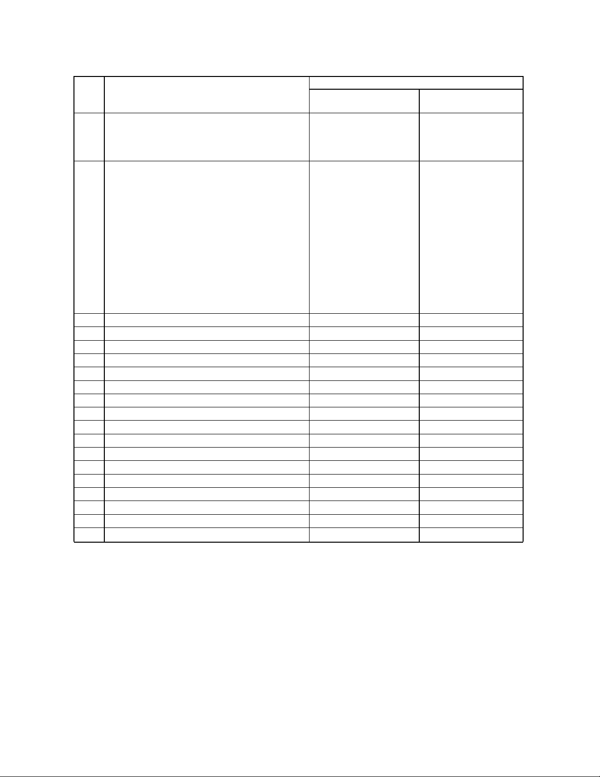
Repair Parts Listing
Part Numbers
Key Model No. Model No.
No. Description CF3000BS00 CF3000ORB00
* Hanger Pack, Consisting of: 761655-27 761655-65
1 Hanger Bracket — —
2 Hanger Ball — —
3 Downrod - 6” — —
* Parts Bag Containing: 763439-1 763439
4 Pin, Clevis (1) — —
5 Clip, Hairpin (1) — —
6 Wire Connector, 12 Ga. (5) — —
7 Setscrew (1) — —
8 Setscrew Wrench, Hex. 5/32” (1) — —
9 Threaded Stud, 1-1/4” (2) — —
10 Lockwasher, External Tooth #8 (2) — —
11 Knurled Knob, #8-32 (2) — —
12 Screw, Flat Head CR #10-24 x 15mm (21) — —
13 Screw, Pan Head CR #8-32 x 10mm (4) — —
14 Screw, Pan Head & Lockwasher #8-32 x 12mm (4) — —
15 Balancing Kit (1) — —
16 Cover, Ceiling (1) 763419-BS 763419-ORB
17 Cover, Switch Housing (1) 763420-BS 763420-ORB
18 K55XL Motor (1) 762508 762508
19 Reverse Module 763492 763492
20 Capacitor, Aux. (1) 763493 763493
21 Hub, Motor 760601 760601
22 Center Housing (1) 763425-BS 763425-ORB
23 Mounting Hub, Flange (1) 763424 763424
24 Lower Housing (1) 763435-BS 763435-ORB
25 Light Kit Assembly (1) 763440 763440
26 Bulb,Halogen, 75-Watt Mini-Candelabra 762737 762737
27 Glass, Lower (1) 763437 763437
28 Cover, Decorative Light (1) 763438-BS 763438-ORB
29 Blade Assembly (5 per set) 763426-1 763426
30 Receiver, SW105 (1) 762401 762401
31 Transmitter, SW114 Wall Control (1) 763497 763497
—
Owner's Manual BP7349 BP7349
Before discarding packaging material, be certain all parts have been removed.
HOW TO ORDER REPAIR PARTS
WHEN ORDERING REPAIR PARTS, ALWAYS GIVE THE FOLLOWING INFORMATION:
The model number of your Fan will be found on a label attached to the top housing.
For repair parts, phone 1-800-654-3545.
• PART DESCRIPTION
• MODEL NUMBER
• PART NUMBER
• NAME OF ITEM
U.L. Model No.: CF3000
Page 16
LIMITED WARRANTY
What The Warranty Covers:
This warranty covers the motor and the other components and accessories of your Emerson ceiling fan against all defects in
workmanship and materials. You must be the original purchaser or user of the product to be covered.
What The Period Of Coverage Is:
As it applies to the motor, this warranty will last for a lifetime of your ceiling fan. All other components and accessories are
covered by this warranty for one year from the date you purchased your ceiling fan. ANY IMPLIED WARRANTY OF MERCHANTABILITY OR FITNESS FOR A PARTICULAR PURPOSE, MADE WITH RESPECT TO COMPONENTS AND ACCESSORIES IS
ALSO LIMITED TO ONE YEAR.
What Will Emerson Electric Co. Do To Correct Problems:
Emerson Electric Co. will replace a defective Emerson Air Comfort Ceiling Fan motor, blade, component or other accessory at
no charge to you. If repair of the motor or blades is not practical or possible within a reasonable time and no replacement can
be provided, Emerson Electric Co. will refund the actual purchase price of your fan. We will ship the repaired product or
replacement to you at no charge, but you are responsible for all costs or removal, reinstallation and shipping of the product to
Emerson Electric Co.
How Can You Get Service:
YOU MUST HAVE PROOF OF YOUR PURCHASE OF THE CEILING FAN TO OBTAIN LIMITED WARRANTY SERVICE. KEEP YOUR
RECEIPT OR OTHER PROOF OF PURCHASE. You can return the product to our factory or to your nearest authorized service
center.
• To return the product to the factory, obtain a return authorization and service identification tag by writing to Air Comfort
Products, Division of Emerson Electric Co., 8100 W. Florissant Ave., St. Louis, MO 63136. Include all model numbers shown
on the product with your request.
• To return the product to an authorized service center, call 1-800-654-3545 for the address of the nearest authorized service
center.
You will be responsible for all insurance, freight or other transportation charges to our factory or authorized service center.
Your Emerson Air Comfort Ceiling Fan should be properly packed to avoid damage in transit since we will not be responsible
for any such damage.
What Is Not Covered:
The glass globes and light bulbs of your ceiling fan are not covered by this warranty. This warranty also does not cover any
defects, malfunctions or failures caused by:
• Repairs by persons not authorized by Emerson Electric Co.,
• Use of parts or accessories not authorized by Emerson Electric Co.,
• Mishandling, improper installation, modifications or damage to your ceiling fan while in your possession, or
• Unreasonable use, misuse, abuse, including failing to do reasonable and necessary maintenance, and normal wear and tear.
Additionally, this warranty and any implied warranty of merchantability or fitness for a particular purpose are voided when:
• The original purchaser or user ceases to own the product, or
• The fan is moved from its original point of installation.
This warranty is only valid within the 50 states of the United States and the District of Columbia. No other written or oral warranties apply, and no employee, agent, dealer or other person is authorized to give any warranties on behalf of Emerson Electric
Co.
REPAIR, REPLACEMENT OR A REFUND ARE THE EXCLUSIVE REMEDIES AVAILABLE UNDER THIS WARRANTY AND EMERSON IS NOT RESPONSIBLE FOR DAMAGES OF ANY KIND, INCLUDING INCIDENTAL AND CONSEQUENTIAL DAMAGES.
Incidental damages include but are not limited to such damages as loss of time and loss of use. Consequential damages
include but are not limited to the cost of repairing or replacing other property which was damaged if this product does not work
properly.
How State Law Relates To The Warranty:
Some states do not allow the exclusion or limitation of incidental or consequential damages so the above exclusion or limitation may not apply to you. This warranty gives you specific legal rights, and you may also have other rights which vary from
state to state.
Air Comfort Products
DIVISION OF EMERSON ELECTRIC CO.
8100 W. Florissant • St. Louis, MO 63136
Part No. F40BP73490000 Printed in China 09/07 Form No. BP7349
U.L. Model No.: CF3000
 Loading...