

Emerson EMC DX-202, DX-205, DX-318, DX-430, DX-450 User Manual
...
Artisan Technology Group is your source for quality
new and certied-used/pre-owned equipment
• FAST SHIPPING AND
DELIVERY
• TENS OF THOUSANDS OF
IN-STOCK ITEMS
• EQUIPMENT DEMOS
• HUNDREDS OF
MANUFACTURERS
SUPPORTED
• LEASING/MONTHLY
RENTALS
• ITAR CERTIFIED
SECURE ASSET SOLUTIONS
SERVICE CENTER REPAIRS
Experienced engineers and technicians on staff
at our full-service, in-house repair center
Instra
Remotely inspect equipment before purchasing with
our interactive website at www.instraview.com
Contact us: (888) 88-SOURCE | sales@artisantg.com | www.artisantg.com
SM
REMOTE INSPECTION
View
WE BUY USED EQUIPMENT
Sell your excess, underutilized, and idle used equipment
We also offer credit for buy-backs and trade-ins
www.artisantg.com/WeBuyEquipment
LOOKING FOR MORE INFORMATION?
Visit us on the web at www.artisantg.com for more
information on price quotations, drivers, technical
specications, manuals, and documentation

EMERSON EMC
POSITIONING DRIVES & MOTORS
- - -
Including IOM-1, PCM-1, PCM-5
T-16, Thumbwheels, and Parallel Programming
Other Manuals available, but bound separately:
T-21 Data Entry Panel
Information furnished by EMERSON EMC is believed to be
accurate and reliable. However, no responsibility is assumed
by MERSON EMC for its use. EMERSON EMC reserves the
right to change the design or operation of the equipment
described herein and any associated motion products without
notice. EMERSON EMC also assumes no responsibility for
any errors that may appear in this document. Information in
this document is subject to change without notice.
P/N 400221-00 REV: A7
DATE: 6/24/92
- 1 -
Artisan Technology Group - Quality Instrumentation ... Guaranteed | (888) 88-SOURCE | www.artisantg.com

TABLE OF CONTENTS
INTRODUCTION....................................................................................................................................................... 6
OVERVIEW ............................................................................................................................................................. 6
S
YSTEM OVERVIEW ................................................................................................................................................... 7
I
NTRODUCTION TO THE BASIC POSITIONING DRIVE AMPLIFIER ................................................................................... 8
P
ERIPHERALS ............................................................................................................................................................. 9
O
PERATOR INTERFACE............................................................................................................................................. 10
T-21 D
ATA ENTRY TERMINAL ................................................................................................................................. 10
T-16 N
UMERIC DISPLAY.......................................................................................................................................... 10
TW-XXX T
POSITIONING DRIVE SPECIFICATIONS......................................................................................................... 12
DX-SERIES MOTORS AND AMPLIFIERS TYPICAL SPEED TORQUE CURVES ........................................ 15
INSTALLATION...................................................................................................................................................... 17
ASSEMBLY AND INSTALLATION CONSIDERATIONS ................................................................................ 17
TYPICAL 120 VAC LINE SIZING (SINGLE PHASE MODELS)....................................................................... 18
TYPICAL 230 VAC 3 PHASE MODELS.............................................................................................................. 19
AMPLIFIER MOUNTING INFORMATION ........................................................................................................ 27
AMPLIFER I/O LOCATIONS............................................................................................................................... 32
MOTOR MECHANICAL INFORMATION.......................................................................................................... 36
MOTOR WIRING .................................................................................................................................................. 43
MAIN/AUXILIARY AX
CABLE WIRING DIAGRAMS.............................................................................................................................. 48
HUMBWHEEL INTERFACE...................................................................................................................... 10
Wiring Considerations .......................................................................................................................................................20
Safety Considerations ........................................................................................................................................................21
Brake Option......................................................................................................................................................................21
Power Line......................................................................................................................................................................... 21
Grounding Considerations .................................................................................................................................................23
Electrical Noise..................................................................................................................................................................25
Magnetic Coil Noise ..........................................................................................................................................................25
Mechanical Consideration..................................................................................................................................................26
Load Coupling ...................................................................................................................................................................26
Selecting An Enclosure......................................................................................................................................................27
Amplifier Losses................................................................................................................................................................ 27
System Troubleshooting ....................................................................................................................................................27
POWER ......................................................................................................................... 46
TDS/TDL CABLE.............................................................................................................................................................48
TDT Cable .........................................................................................................................................................................48
Optional Bulkhead Connectors ..........................................................................................................................................49
OPERATING MODES............................................................................................................................................. 50
MODE SELECTION .............................................................................................................................................. 51
POSITIONING DRIVE CONFIGURATION AND PROGRAMMING ............................................................. 57
How To Start......................................................................................................................................................................58
PCX Program Revision...................................................................................................................................................... 58
Moving Through The Menus .............................................................................................................................................58
Changing Values In The Data Enter Screens .....................................................................................................................58
USING PCX DISK FILES...................................................................................................................................... 59
1. Data File........................................................................................................................................................................59
2. List File.........................................................................................................................................................................59
On-line Operations.............................................................................................................................................................60
ESTABLISHING COMMUNICATIONS .............................................................................................................. 62
DISK FILE OPERATIONS .................................................................................................................................... 63
DRIVE SETUP ....................................................................................................................................................... 64
LIMITS ................................................................................................................................................................... 68
INDEXING OPERATION MODE......................................................................................................................... 70
JOG ......................................................................................................................................................................... 75
HOME..................................................................................................................................................................... 76
OVERVIEW OF BASIC OPERATION MODES.................................................................................................. 84
Serial Mode........................................................................................................................................................................84
- 2 -
Artisan Technology Group - Quality Instrumentation ... Guaranteed | (888) 88-SOURCE | www.artisantg.com

Output Functions................................................................................................................................................................87
Input Functions ..................................................................................................................................................................88
DIAGNOSTICS......................................................................................................................................................... 98
F -POSITION ERROR FAULT............................................................................................................................ 100
FAULT INDICATOR CODES............................................................................................................................. 101
STABILIZATION OF HIGH INERTIA LOADS ................................................................................................ 106
INSTALLATION OF THE IOM-1 ....................................................................................................................... 107
INPUT/OUTPUT INTERFACE ........................................................................................................................... 108
Output Functions..............................................................................................................................................................110
Input Functions ................................................................................................................................................................111
EXAMPLES OF I/O CONNECTIONS TO THE IOM-1 ..................................................................................... 112
Detailed Description of Additional I/O Functions With the Addition of the IOM-1........................................................113
Input Functions ................................................................................................................................................................113
Output Function ...............................................................................................................................................................113
PARALLEL INTERFACE .................................................................................................................................... 114
CUSTOMER SUPPLIED THUMBWHEEL INTERFACE ................................................................................. 115
Thumbwheel Wiring........................................................................................................................................................116
PARALLEL PROGRAMMING INTERFACE ................................................................................................... 123
THUMBWHEEL AND PARALLEL PROGRAMMING SETUP AND OPERATION................................... 129
THUMBWHEEL AND PARALLEL PROGRAMMING INTERFACE ............................................................. 129
DATA FIELD NUMBER ................................................................................................................................................129
DATA FIELD PURPOSE................................................................................................................................................130
INDEX NUMBER ................................................................................................................................................ 131
T-16 SETUP AND OPERATION ........................................................................................................................ 136
INSTALLATION AND CONNECTIONS OF THE PCM-1 ............................................................................... 138
INPUT/OUTPUT INTERFACE (PCM-1)............................................................................................................ 139
OVERVIEW ......................................................................................................................................................... 139
O
UTPUT FUNCTIONS .............................................................................................................................................. 141
WHAT ARE PROGRAMS?................................................................................................................................. 147
DESCRIPTION OF PROGRAMMING FUNCTIONS ........................................................................................ 149
WAIT FOR INPUT..........................................................................................................................................................149
DWELL TIME.................................................................................................................................................................149
UPDATE OUTPUTS.......................................................................................................................................................149
EXECUTE INDEX..........................................................................................................................................................149
EXECUTE PROGRAM...................................................................................................................................................149
EXECUTE COMPOUND INDEX ..................................................................................................................................149
END .................................................................................................................................................................................149
HOW TO CREATE A PROGRAM...................................................................................................................... 151
PROGRAMMING CAPABILITIES .................................................................................................................... 154
SUSPEND/RESUME FUNCTIONS...................................................................................................................... 155
E
XTENDED SUSPEND/RESUME PROGRAMMING...................................................................................................... 156
INSTALLATION AND CONNECTIONS OF PCM-5........................................................................................ 158
SYNCHRONIZATION CABLE........................................................................................................................... 159
SCS-2 SYNC
ENCODER..................................................................................................................................... 161
BASIC OPERATION ........................................................................................................................................... 162
Some Application Examples............................................................................................................................................162
BI-POLAR SYNCHRONIZATION ..................................................................................................................... 168
ADDITIONAL PCM-5 PROGRAMMING .......................................................................................................... 177
PARAMETERS .................................................................................................................................................... 177
LEAD AXIS.......................................................................................................................................................... 177
SYNC RATIO....................................................................................................................................................... 177
SYNC VELOCITY SCALE FACTOR AND SYNC VELOCITY DECIMAL POINT ....................................... 178
BI-POLAR SYNC ENABLED............................................................................................................................. 179
INDEX, HOME .................................................................................................................................................... 179
PROGRAMS......................................................................................................................................................... 180
- 3 -
Artisan Technology Group - Quality Instrumentation ... Guaranteed | (888) 88-SOURCE | www.artisantg.com

SERIAL INTERFACE ........................................................................................................................................... 182
EXAMPLE OF A SERIAL MULTI-DROP CONNECTION............................................................................... 183
SERIAL SIGNAL FLOW DIAGRAMS............................................................................................................... 183
SETTING UP THE SERIAL INTERFACE SWITCHES AND PROTOCOL ..................................................... 184
LOCATIONS OF SWITCHES ............................................................................................................................. 184
SERIAL CABLES ................................................................................................................................................ 186
Wiring Diagrams From Computer to Drive .....................................................................................................................186
Wiring Diagram for DD-XXX Multi-Drop Cable............................................................................................................187
SERIAL INTERFACE CONTROL...................................................................................................................... 188
ASCII COMMANDS............................................................................................................................................ 189
SUMMARY OF SERIAL COMMANDS.............................................................................................................. 210
INDEX...................................................................................................................................................................... 216
- 4 -
Artisan Technology Group - Quality Instrumentation ... Guaranteed | (888) 88-SOURCE | www.artisantg.com

CUSTOMER SERVICE
Emerson EMC offers a wide range of services to support our customers’ needs. Listed below are
some examples of these services.
SERVICE SUPPORT (612) 474-8833
Emerson Electronic Motion Control’s products are backed by a team of professionals who will
service your installation wherever it may be. Our Customer Service Center in Minneapolis,
Minnesota, is ready to help you solve these occasional problems over the telephone. It’s there, at
the Center, that we are available 24 hours a day for emergency service to help speed any problem
solving. Also, all hardware replacement parts, should they ever be needed, are available through
our customer service organization. Need on-site help? Emerson provides on-site service, in
most cases, the next day. Just call Emerson’s Customer Service Center when on-site service or
maintenance is required.
TRAINING SERVICES (612) 474-1116
Emerson EMC maintains a highly trained staff of instructors to familiarize customers with
Emerson Electronic Motion Controls and their applications. A number of courses are offered,
many of which can be taught in your plant upon request.
APPLICATION ENGINEERING (612) 474-1117
An experienced staff of factory Application Engineers provides complete customer support for
tough or complex applications. Our engineers offer you a broad base of experience and
knowledge of electronic motion control applications.
- 5 -
Artisan Technology Group - Quality Instrumentation ... Guaranteed | (888) 88-SOURCE | www.artisantg.com

INTRODUCTION
OVERVIEW
The EMERSON EMC Positioning Drives are the first servo products specifically designed to
offer high performance position control without the maze of boards, wires, connectors, pot
adjustments and transformers normally associated with servo systems. The DX-Series drives
support brushless motors and range in size from 2 in-lbs. To 400 in-lbs., continuous. Special
care in motor selection has resulted in drives that have excellent torque to inertia ratios.
The drives consist of ruggedly constructed enclosures which contains all the required
components for position and velocity control. The drives also provide connections for
interfacing with external machine inputs and outputs, and logic control, along with a serial
interface port that is used to program the drive.
Calibration
Calibration of the Positioning Drive is virtually eliminated because all user potentiometer
adjustments have been eliminated. The potentiometer adjustments have been replaced by
firmware. The software pre-sets the compensation values and continuously adjusts these values
during motion. This allows the system to operate over a large inertial range without any manual
adjustments or tuning required.
Installation
Installation and wiring is fast and easy because the Positioning Drive operates in most
environments directly from an AC line source without requiring a separate isolation transformer.
The unit is designed to be back mounted within a standard Nema enclosure typically found in a
production facility. The size has also been minimized to allow users to reduce the space
requirements for incorporating a servo control into their production machinery.
Motor
Each Positioning Drive includes a high performance servo motor whose characteristics have
been matched to the drive amplifier. Thus, the chance for a mismatch between the motor and the
Positioning Drive is eliminated.
Programming and Troubleshooting
EMERSON EMC provides an easy to use software programming package with every drive that
operates on an IBM PC/XT/AT or compatible computer with 512K bytes of RAM and a serial
interface port. This software makes the Positioning Drive simple to program even for first time
servo users. It is almost essential that the user of the positioning servo drive have access to a
personal computer (PC). The PC can be used to change data, up and down load data and most
importantly, help solve problems during operation and startup.
- 6 -
Artisan Technology Group - Quality Instrumentation ... Guaranteed | (888) 88-SOURCE | www.artisantg.com

System Overview
Following are the specific model numbers used in configuring the Positioning Drives.
Table I Positioning Drive Components
DX-202 (2 in-lbs.) DXA-202 Amplifier
DXM-202 Motor
TDT-XX Cable
DX-205 (5 in-lbs.) DXA-205 Amplifier
DXM-202 Motor
TDT-XX Cable
DX-308 (8 in-lbs.) DXA-308 Amplifier
DXM Motor
TDL-XX Cable
DX-318 (18 in-lbs.) DXA-318 Amplifier
DXM Motor
TDL-XX Cable
DX-430 (30 in-lbs.) DXA-430 Amplifer
DXM or DXE-430 Motor*
TDL-XX Cable
DX-450 (50 in-lbs.) DXA-450 Amplififer
DXM or DXE-430 Motor*
TDL-XX Cable
DX-480 (80 in-lbs.) DXA-480 Amplifier
DXM or DXE-480 Motor*
TDL-XX Cable
DX-780 (80 in-lbs.) DXA-780 Amplifier
DXM-780 Motor
TDL-XX Cable
DX-7120 (120 in-lbs.) DXA-7120 Amplifier
DXM-7120 Motor
TDL-XX Cable
DX-6120 (120 in-lbs.) DXA-6120 Amplifier
DXM-6120 Motor
RC-XX Cable
DX-6200 (300 in-lbs.) DXA-6200 Amplifier
DXM-6200 Motor
RC-XX Cable
DX-6300 (300 in-lbs.) DXA-6300 Amplifier
DXM-6300 Motor
RC-XX Cable
DX-8200 (200 in-lbs.) DXA-8200 Amplifier
DXM-8200 Motor
DX-8300 (300 in-lbs.)
DX-8400 (400 in-lbs.) DXA-8400 Amplifier
NOTE: The DX-8XXX series motor and Amplifiers are interconnected Via screw terminals so as to
allow for customer provided wiring Not to exceed 100ft.
NOTE: XX = CABLE LENGTH (FT)15
25 25
50 50
*NOTE: DX-430, DX-450 and DX-480 Drives can be provided with Motors that have either typical
English or metric flange and Shaft dimensions. The metric motor is designated with a DXM
prefix and the English version is designated with a DXE prefix.
DXA-8300 Amplifier
DXM-8300 Motor
DXM-8400 Motor
- 7 -
Artisan Technology Group - Quality Instrumentation ... Guaranteed | (888) 88-SOURCE | www.artisantg.com

Introduction to the basic positioning drive amplifier
The Positioning Drive amplifier is different from common analog amplifiers in that it includes a
position feedback loop and the electronics to control motion functions. To accomplish this, the
motor uses resolver feedback. The resolver converter electronics in the amplifier develops
velocity and position feedback signals required for high performance and precise velocity and
position control.
In addition the amplifier offers three standard modes of control providing a host of alternatives
for implementing real time motion control.
In the ANALOG TORQUE or VELOCITY mode, the amplifier responds to a conventional +/10 volt signal. Most variable speed drives and servo amplifiers on the market today receive
commands via analog input.
The true power and versatility of the Positioning Drive is best utilized in the additional
positioning control modes. In most applications the user will use one of the following modes of
operation.
In the PULSE mode, the drive responds to a serial pulse train representing externally generated
incremental position change commands. These commands are normally in the form of CW or
CCW directional pulses. This mode is commonly used to control DC stepper motors or numeric
controlled (CNC) machinery.
The INDEXING mode allows up to thirty-two different indexes or positions to be preprogrammed and stored in a non-volatile memory. These indexes plus other commands such as
STOP and JOG are selected easily by the drive’s parallel input/output (I/O) lines from devices
such as PLCs or operator push buttons. Parallel I/O commands can be used for stand alone
operation or, simultaneously in conjunction with any other two control modes.
Another powerful feature of the INDEXING mode allows ASCII commands through the
standard RS423 serial interface. This interface port allows the user to down load new
dimensional data e.g., position, distance, velocity, etc., and command an internally generated
index using those parameters. These ASCII serial commands are well suited to operation from
the RS232C serial interface on an IBM Personal Computer (PC) or Programmable Logic
Controller (PLC) with ASCII or Basic Module.
For additional stand alone motion control capability, the drive is designed to accept a series of
application oriented modules called “PCM” modules. The PCMs can be attached to any drive by
simply plugging them onto the front. The PCM is designed to share the power supply inside of
the drive and includes 12 additional optically isolated inputs/outputs (making a total of 24).
When attached, the PCM module extends the operation of the Positioning Drive system.
The IOM-1, PCM-1, PCM-2 and PCM-5 modules are designed to be plug-on additions to
EMERSON EMC’s line of Positioning Drives. Each module is intended to enhance a specific
performance characteristic of the positioning drives.
- 8 -
Artisan Technology Group - Quality Instrumentation ... Guaranteed | (888) 88-SOURCE | www.artisantg.com

Peripherals
IOM-1 Input/Output Expander Module
The IOM Module mounts to the front of the basic drive to double the I/O capability for those
applications where the number of inputs and outputs provided with the basic unit are not
adequate for interfacing motion to the machine logic controllers. Each of these lines are
optically isolated and can be connected in either a current sinking or current sourcing
arrangement. In addition, the IOM-1 includes the parallel interface port required for connecting
1 or 2 thumbwheels and 1 remote display or parallel communications with a PLC.
PCM-1
The PCM-1 module converts the basic Positioning Drive from a “smart” servo drive system with
indexing capabilities into a motion control system capable of executing numbered sequences of
indexes called motion programs. Each motion program combines basic indexes to achieve
complex motion profiles beyond what is possible with the basic drive. In addition, the PCM
module greatly increases the non-volatile memory storage capability of the standard digital drive.
This allows the user greater flexibility in both the size and the number of programs (and indexes)
available. Another advantage of PCM-1 is that it increases the number of input lines from 8 to
16 and the number of output lines is increased from 4 to 8. All inputs and outputs are assignable
from a standard list of I/O functions. Lastly, the PCM-1 allows the user to create compound
indexes and includes the parallel interface port required for connecting 1 or 2 thumbwheels and 1
remote display or parallel communications with a PLC.
PCM-5
The PCM-5 has most of the capability of the PCM-1. The PCM-5 is able to do electronic
synchronized line shafting and ratio control. This is accomplished by using an external encoder
or drive representing a lead axis connected to the PCM-5. The drive with the PCM-5 can then be
synchronized to the lead device. This mode of operation also allows for pulse counting of the
lead device and indexing at velocities proportional to its speed. With this capability, flying
shear/cutoff applications can easily be configured.
- 9 -
Artisan Technology Group - Quality Instrumentation ... Guaranteed | (888) 88-SOURCE | www.artisantg.com

Operator Interface
Emerson EMC can provide three different peripheral devices to enhance the operator friendliness
of your drive. The T-21 Data Entry Terminal is ideally suited for providing machine operators
with the ability to enter and/or alter and display machine motion parameters controlled by
Emerson Digital Positioning Servo Drive. The T-16 displays position and velocity parameters
using large sized LEDs that are visible from several feet away. Emerson EMC offers a simple
thumbwheel interface called a TW-XXX that is offered in many different configurations. The
TW-XXX is used to change data of a specific motion parameter or parameters. The thumbwheel
option is ideal for applications needing minimum operator interface.
T-21 Data Entry Terminal
The T-21 communicates with any Emerson Positioning Drive using serial ASCII codes and
allows the machine designer to access, display, or alter certain motion parameters such as index
length. For frequently accessed motion parameters, the operator cam simply depress one of three
user programmable function switches located on the front panel. By depressing the correct
function key, the proper user created message is displayed. The message can be created to
include information as to what setup parameter is being changed, on which axis, etc. If more
than 3 operator altered setup parameters are required, a fourth F(x) key allows the user to store
up to 95 additional operator alterable setup functions.
T-16 Numeric Display
The T-16 is used to display position or velocity of the drive. The T-16 has 7 large LEDs that are
visible from several feet away. This allows the operator to view data shown on the display from
different positions on a machine. The T-16 requires the use of the ION-1 or a PCM-1 module.
The T-16 plugs into the parallel port on the module.
TW-XXX Thumbwheel Interface
The thumbwheel interface provides the user with a non-serial interface method for making
changes to specific motion functions. The user can set up the thumbwheel to change velocities,
distances/positions, dwell times, index counts, and acceleration and deceleration times. All the
thumbwheels are mounted in a small, self contained enclosure. Cables can be ordered in specific
lengths from 3 feet to 50 feet. The TW-XXX requires the user to have an IOM-1 or a PCM-1
module. The TW-XXX plugs into the parallel port on the module.
- 10 -
Artisan Technology Group - Quality Instrumentation ... Guaranteed | (888) 88-SOURCE | www.artisantg.com

FAMILY OF POSITIONING DRIVE PRODUCTS
Figure 1 Peripherals
Artisan Technology Group - Quality Instrumentation ... Guaranteed | (888) 88-SOURCE | www.artisantg.com
- 11 -

POSITIONING DRIVE SPECIFICATIONS
Specifications +/- 10%
Table II Positioning Drive Specifications
DRIVE PERFORMANCE
Drive Model#Motor
Model #
DX-202 DXM-202 2/4 .0000855 3000 7 AMP 2A(S.B.) 1.8 23 1.1/2.2
DX-205 DXM-205 5/10 .000253 3000 7 AMP 2A(S.B.) 1.8 23 3.0/6.0
DX-308 DXM-308 8/16 .0005 3000 7 AMP 2A(S.B.) 2.9 34 2.8/5.6
DX-318 DXM-318 18/36 .001 3000 10 AMP 5A(S.B.) 3.38 40 5.4/10.8
DX-430 DXM-430 30/60 .0026 3000 15 AMP 5A(S.B.) 3.38 40 8.9/17.8
DX-450 DXM-450 50/85 .0052 3000 25 AMP 5A(S.B.) 3.38 40 14.8/24.0
DX-480 DXM-480 80/160 .00772 3000 30 AMP 8A(S.B.) 3.36 42 24/48
DX-780 DXM-780 80/160 .013 3000 30 AMP 8A(S.B.) 3.38 40 24/48
DX-7120 DXM-7120 120/240 .021 2000 30 AMP 8A(S.B.) 5.57 66 24/48
DX-6120 DXM-6120 120/240 .0096 3000 15 AMP 7A 8 100 15/30
DX-6200 DXM-6200 200/400 .0192 3000 20 AMP 7A 8 100 25/50
DX-6300 DXM-6300 300/600 .0268 3000 30 AMP 10A 8 100 38/76
DX-8200 DXM-8200 200/300 .04 3000 20 AMP 7A 7.4 96 27/41
DX-8300 DXM-8300 300/450 .08 3000 30 AMP 10A 7.4 96 40/60
DX-8400 DXM-8400 400/600 .12 3000 40 AMP 10A 7.4 96 54/81
INPUT VOLTAGE: DX-202, DX-205, DX-308, DX-430, DX-450, DX-480, DX-780, DX-
INPUT VOLTAGE: DX-6120, DX-6200, DX-6300, DX-8200, DX-8300, DX-8400 = 196-
SWITCHING FREQUENCY: DX-202, DX-205, DX-308, DX-430 = 20 Khz
DEAD BAND: Zero
VELOCITY SIGNAL INPUT: ±10 vdc typical (10 bit resolution speed selection ±10 volt)
TORQUE SIGNAL INPUT: ± vdc typical (10 bit resolution speed selection ±10 volt)
PULSE MODE INPUT: TTL compatible, 500 nsec minimum pulse width, 210 Khz max
ANGULAR ACCURACY: Cable Length 15FT
USER UNITS/REV: Programmable Range (200-25000)
AMPLIFIER THERMAL SHUT DOWN AS DETECTED IN POWER STAGE:
All Drives: 80º - 90º C
MOTOR THERMAL SHUT DOWN AS DETECTED IN MOTOR (CASE TEMP):
All Motors: 100º - 115º C
Torque
Cont/Peak
IN/LBS
Rotor Interia
IN/LBS/SEC
Max. RPM Bus Fuse Shunt Fuse KT
IN-LBS/AMPKEVolts/KRPM
7120 = 96-132 VAC, 50/60 Hz, single phase
264 VAC 3 PHASE 50/60 Hz
DX-450, DX-480, DX-780, DX-7120 = 15 Khz
DX-6120, DX-6200 = 15 Khz
DX-6300 = 12 Khz
DX-8200, DX-8300, DX-8400 = 10 Khz
frequency
50FT 100FT
Minutes ±20 ±30 ±40
Amplifier
Current
Ratings
- 12 -
Artisan Technology Group - Quality Instrumentation ... Guaranteed | (888) 88-SOURCE | www.artisantg.com

OPTIONAL FAIL-SAFE BRAKE: (Activated by the Positioning Drive)
Table III Fail Safe Brake
Model Holding Torque
IN-LBS
DX-308 12
DX-318 25
DX-430 45
DX-450 75
DX-480 120
DX-780 120
DX-7120 180
DX-6120 400
DX-6200 400
DX-6300 400
*DX-8200 300
*DX-8300 450
*DX-8400 600
*Special (consult factory)
COMMAND PULSE: 5-15 vdc
MODE INPUTS: 25-70 milliamps
ANALOG INPUTS: -10 vdc to +10 vdc operating range
-12 vdc to +12 vdc absolute maximum
Different input greater than 9K ohms
SERIAL INTERFACE: RS423 signal compatible
Xmit, Rec, and GND
INPUTS AND OUTPUTS: Outputs: sink or source (2 terminals);
200 Ma max (external current limit required) each
Inputs: 10 to 30 vdc (internal current limit provided)
10, 12, 15 and 24 vdc typical
Table IV User Memory Capacity
User Memory Capacity
Drive
Drive
w/IOM-1
Jog 2 2 2 2
Home 1 1 1 1
Indexes 32 32 256 256
Programs 0 0 64 64
Drive
w/PCM-1
Drive
w/PCM-5
- 13 -
Artisan Technology Group - Quality Instrumentation ... Guaranteed | (888) 88-SOURCE | www.artisantg.com

Table V Number of User Programs
Number of Required
User Programs
1 1000
2 500
3 333
4 250
5 200
--
--
-62 16
63 15
Average Number of Available
Steps Per Program
Table VI Motor Load Specifications
Motor Radial and Axial Load Specifications
Motor Max Radial Load Max Axial Load
DXM-202 10 lbs 8 lbs
DXM-205 10 lbs 8 lbs
DXM-308 20 lbs 15 lbs
DXM-318 20 lbs 15 lbs
DX* -430 50 lbs 20 lbs
DX* -450 50 lbs 20 lbs
DX* -480 75 lbs 40 lbs
DXM-780 150 lbs 50 lbs
DXM-7120 150 lbs 50 lbs
DXM-6120 150 lbs 50 lbs
DXM-6200 150 lbs 50 lbs
DXM-6300 150 lbs 50 lbs
DXM-8200 150 lbs 50 lbs
DXM-8300 150 lbs 50 lbs
DXM-8400 150 lbs 50 lbs
- 14 -
Artisan Technology Group - Quality Instrumentation ... Guaranteed | (888) 88-SOURCE | www.artisantg.com
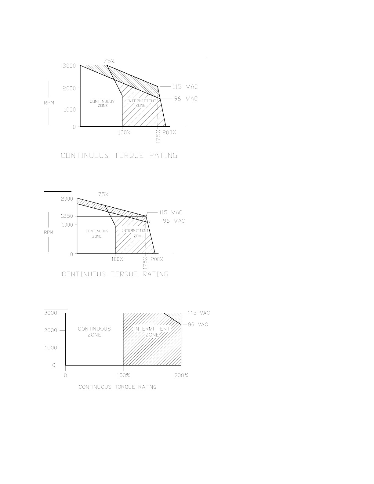
DX-SERIES MOTORS AND AMPLIFIERS TYPICAL SPEED
TORQUE CURVES
DX-202, DX-308, DX-318, DX-430, DX-480, DX-780
Figure 2 Typical Speed Torque Curve
DX-7120
Figure 3 Typical Speed Torque Curve
DX-205
Figure 4 Typical Speed Torque Curve
∗ Continuous torque rating of the motors is measured using a 10” X 10” X 0.25” mounting plate that
acts as a heatsink.
∗ All specifications are ± 10%.
- 15 -
Artisan Technology Group - Quality Instrumentation ... Guaranteed | (888) 88-SOURCE | www.artisantg.com
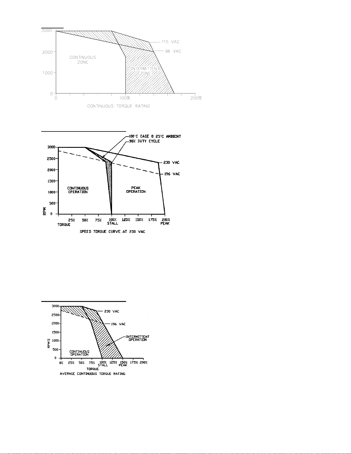
DX-450
Figure 5 Typical Speed Torque Curve
DX-6120, DX-6200, DX-6300
Figure 6 Typical Speed Torque Curve
1) Peak operation is available for ≥1.0 seconds from 0 torque.
2) Speed torque curves are based on 144” sq. by ½” thick aluminum face plate.
3) Derate available torque by 1% per °C for operation above 30°C, to an ambient temperature of
45°C, for motor and amplifier.
DX-8200, DX-8300, DX-8400
Figure 7 Typical Speed Torque Curve
∗ Continuous torque rating of the motors is measured using a 10” X 10” X 0.25” mounting plate that
acts as a heatsink.
∗ All specifications are ± 10%.
Artisan Technology Group - Quality Instrumentation ... Guaranteed | (888) 88-SOURCE | www.artisantg.com
- 16 -

INSTALLATION
OVERVIEW
The Positioning Drives were designed with simple installation in mind. The Drive normally
back-mounts into a standard NEMA enclosure. Because of its small footprint and no need for
external transformers, boards and power supplies, the Positioning Drive saves significant panel
space and cost over alternative servo positioning systems. Wiring and connecting the drive is
equally simple. AC line power is connected via provided screw terminals. All 120 VAC models
use single phase 50/60 Hz power. All 230 VAC models use 3 phase 50/60 Hz power.
Inputs and outputs for control and status are wired to a 12 position, detachable terminal strip (this
also makes servicing easy). The RS423 serial interface used for setup, status and control can be
connected with a 9 pin D-type connector. The motor connections for the 120 VAC single phase
models are accomplished with factory supplied cable and mating connectors. The higher power
230 VAC 3 phase models are connected via screw terminals at the amplifier and motor. This
allows the user to supply his own wire.
The larger drive motors also have NPT pipe thread holes for metallic raceways. It is a
requirement that the stator wiring R, S, T be run in metallic raceways and 1-1/4” pipe conduit
holes are provided. The feedback wiring must be done by using shielded cabling with 100%
shielding via a foil shield and a braided shield.
ASSEMBLY AND INSTALLATION CONSIDERATIONS
The following procedures outline the methods necessary to assure reliable and trouble free
installation of the EMERSON EMC Positioning Drive.
- 17 -
Artisan Technology Group - Quality Instrumentation ... Guaranteed | (888) 88-SOURCE | www.artisantg.com
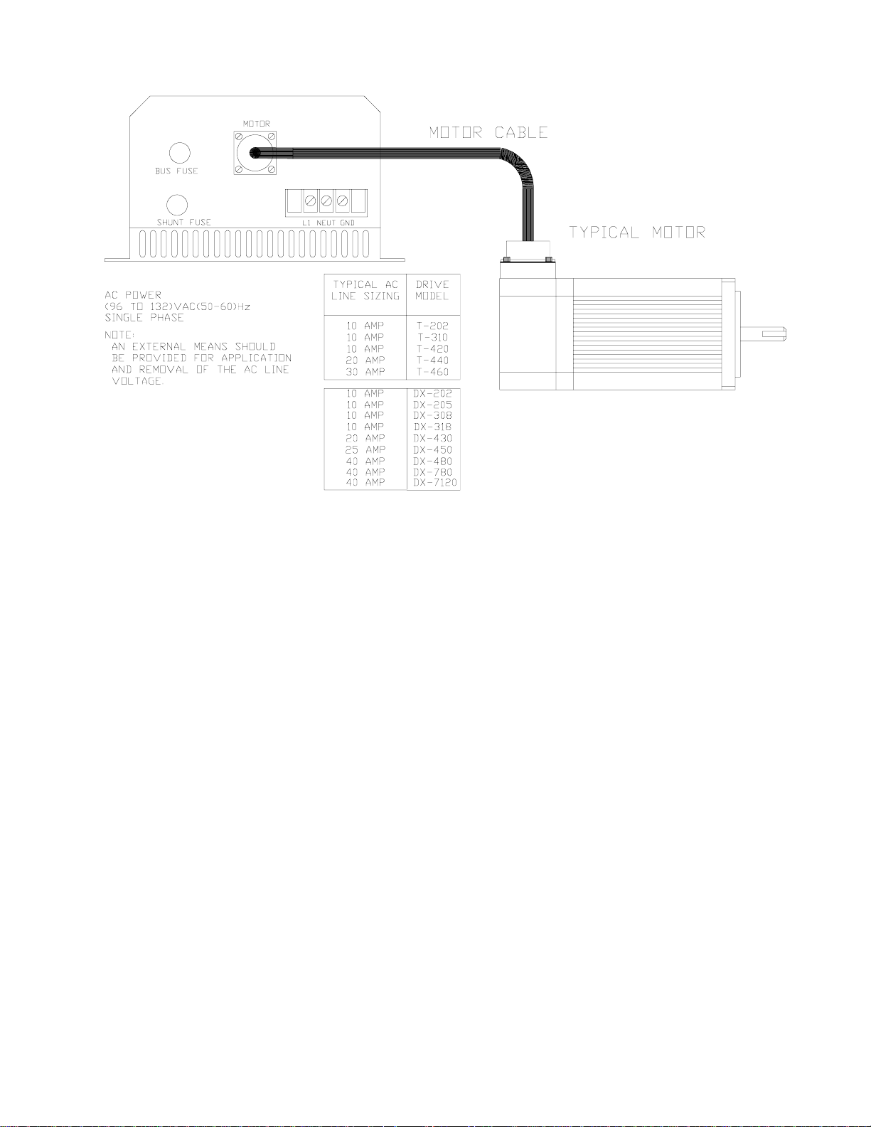
TYPICAL 120 VAC LINE SIZING (SINGLE PHASE MODELS)
Figure 8 Typical 120 VAC Line Sizing
The approximate AC line source VA rating can be determined by multiplying the AC line sizing
by 120 VAC.
Example: DX-780
Line sizing = 40 amp
(40 amps) ∗ (120 VAC) = 4800 VA
- 18 -
Artisan Technology Group - Quality Instrumentation ... Guaranteed | (888) 88-SOURCE | www.artisantg.com
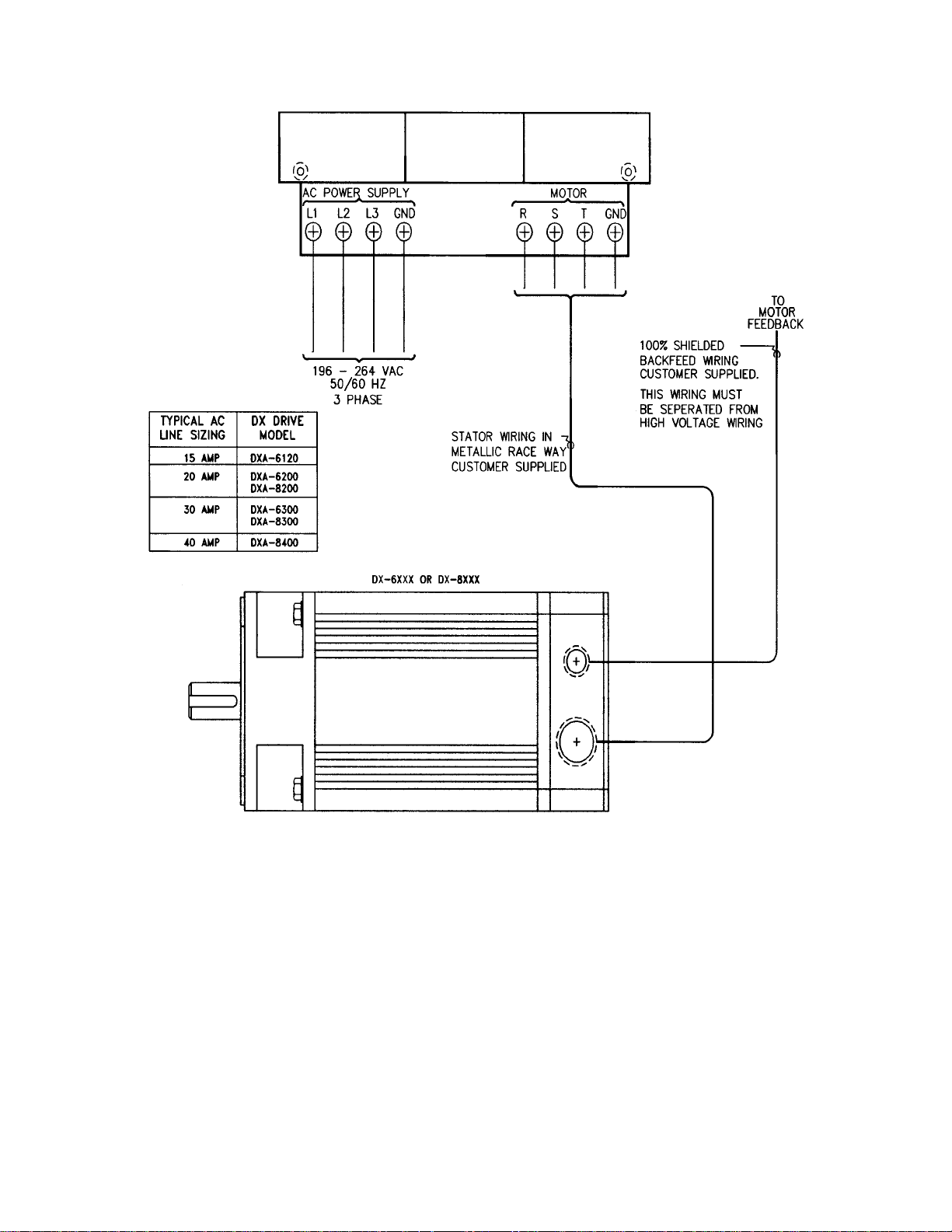
TYPICAL 230 VAC 3 PHASE MODELS
Figure 9 Typical 230 VAC 3 Phase Connections
The approximate AC line source VA rating can be determined by W = E•I 1.732
Example: DX-8200 = 20 Amps
Watts = 230 VAC • 20 Amps • 1.732 = 7,967
- 19 -
Artisan Technology Group - Quality Instrumentation ... Guaranteed | (888) 88-SOURCE | www.artisantg.com

The following table should be used as a guideline for minimum sizing the AC wiring.
Table VII Typical Line Ampacities & Wire Gauges
Drive Typical Line
Ampacities
DX-202 10 A 16 AWG
DX-205 10 A 16 AWG
DX-308 10 A 16 AWG
DX-318 10 A 16 AWG
DX-430 20 A 12 AWG
DX-450 25 A 12 AWG*
DX-480 40 A 10 AWG*
DX-780 40 A 10 AWG*
DX-7120 40 A 10 AWG*
DX-6120 15 A 12 AWG*
DX-6200 20 A 12 AWG*
DX-6300 30 A 10 AWG*
DX-8200 20 A 12 AWG*
DX-8300 30 A 10 AWG*
DX-8400 40 A 8 AWG*
Recommended
Minimum Wire Gauge
* AC power lines that are farther than 50 ft. from the power source, many require a larger gauge that
what is recommended above.
Wiring Considerations
If you are not sure of your grounding or signal wiring techniques, you should observe the
recommended practices according to the IEEE Ground Book, ANSI Standard C1141 and the
National Electric Code.
Wiring of any industrial equipment should be done with some consideration for future
troubleshooting and repair. All wiring should be either color coded or tagged with industrial
wire tabs.
All I/O wiring must be done with industrial grade insulated wire to withstand the environment of
the application. 18 to 24 gauge wire must be used for I/O wiring. The use of larger gauge wire
will cause the I/O terminals to prematurely fatigue. Each input and output to the control unit is
designed to have high noise immunity. This does not mean that high voltage, noise emitting
wiring on the rest of the application can be run adjacent to the control inputs. Precautions should
be taken to eliminate any possible noise from reaching the drive.
- 20 -
Artisan Technology Group - Quality Instrumentation ... Guaranteed | (888) 88-SOURCE | www.artisantg.com

Safety Considerations
The user is responsible for emergency interlock switches. Any master interlock should be wired
to shut down AC power to all parts of the system. Your system should be designed such that
power is disconnected from the output loads any time the equipment is not running, or when the
emergency stop is activated.
Brake Option
An additional safety and operational feature can be added by ordering the optional fail-safe
brake. The brake allows the motor shaft to be held whenever power is removed from the brake
coil (such as in a power failure). The user can control the on/off operation of the brake through
either serial commands or an assigned input line. The power supply needed to operate the brake
is provided internally in the drive.
Power Line
The lower power 120 VAC (DX-202 thru DX-7120) drives are designed to operate on a 50/60
Hz, single phase AC power line. The AC voltage of this power line must be within the specified
range of 96-132 VAC and be free of voltage transients which exceed this range. If it is found
that the AC power does not meet these specifications, further AC line conditioning may be
required. Also, if there is sensitive electronic equipment (digital computer, test equipment, etc.)
operating on the same AC power line as the Drive, additional EMI/RFI filtering may be required
to reduce the effects of conducted AC line noise. Operation at 96 VAC will reduce the drive’s
performance at high (max) speed.
The AC input lines are connected to the drive by means of the 3-position terminal strip located
on the bottom plate of the drive. The AC line wires should be connected as shown below.
Insufficient or incorrectly applied AC line power is a major cause of drive problems. Wiring
sizing and transformer selection (if necessary) should be done carefully.
CAUTION: To insure proper operation after a power down the user should wait a minimum of
10 seconds before reapplication of power.
Figure 10 Typical 120 VAC Drives
• L2 is the AC neutral wire and must be grounded (see “Grounding Considerations”.)
- 21 -
Artisan Technology Group - Quality Instrumentation ... Guaranteed | (888) 88-SOURCE | www.artisantg.com
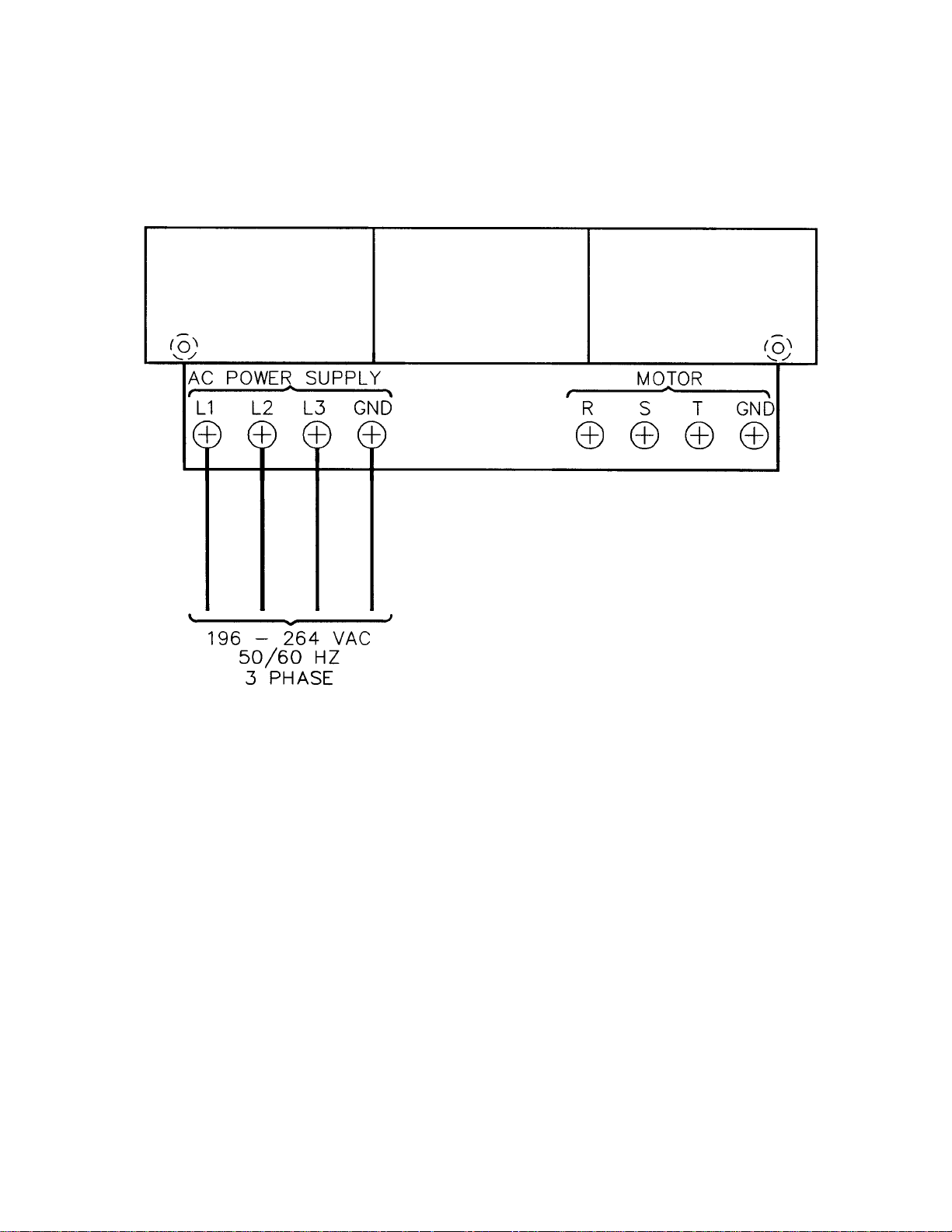
The high power 230 VAC (DX-6120, DX-6200, DX-6300, DX-8200, DX-8300, DX-8400) are
designed to operate on 3 phase AC power. The AC voltage for these drives must be between 196
to 264 VAC.
The AC input lines are connected to the drive by means of the 4 terminals located on the bottom
plate of the drive. The AC line wires should be connected as shown below. Insufficient AC line
power from wire size and control transformers is a major cause of drive problems.
Figure 11 Typical 230 VAC Drives
The GND terminal is bonded to the chassis and must be connected to earth ground.
- 22 -
Artisan Technology Group - Quality Instrumentation ... Guaranteed | (888) 88-SOURCE | www.artisantg.com
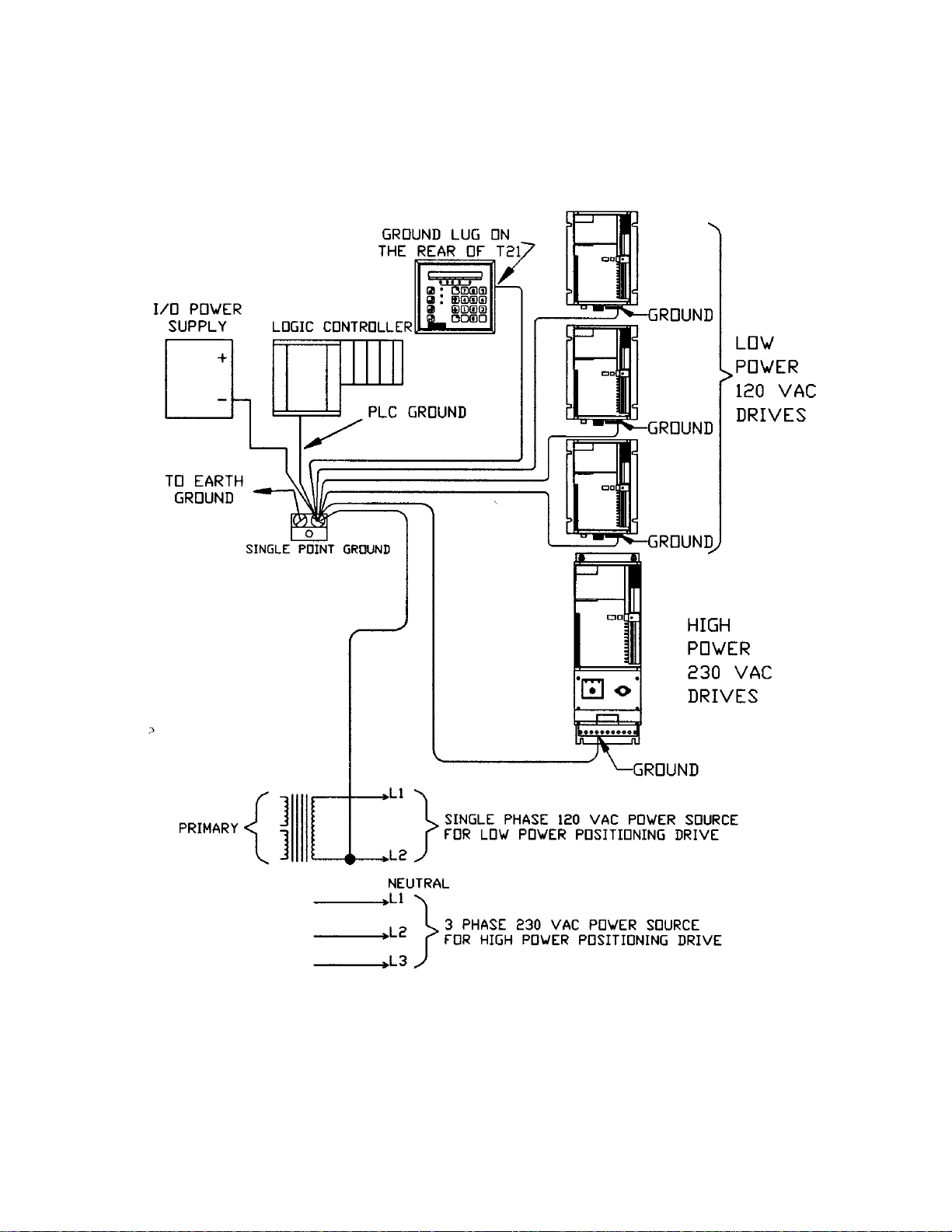
Grounding Considerations
The GND terminal of the drive is internally bonded to the frame. The enclosure ground and the
drive ground should be a common single point that ultimately is a continuous electrical path to
earth ground. The following example illustrates the ideal grounding arrangement of the AC
power.
Figure 12 Grounding Illustration
NOTE: These ground wires should not be shared with other equipment. Also note that the
neutral (L2) for the 120 VAC source for the low power positioning drive is grounded.
- 23 -
Artisan Technology Group - Quality Instrumentation ... Guaranteed | (888) 88-SOURCE | www.artisantg.com
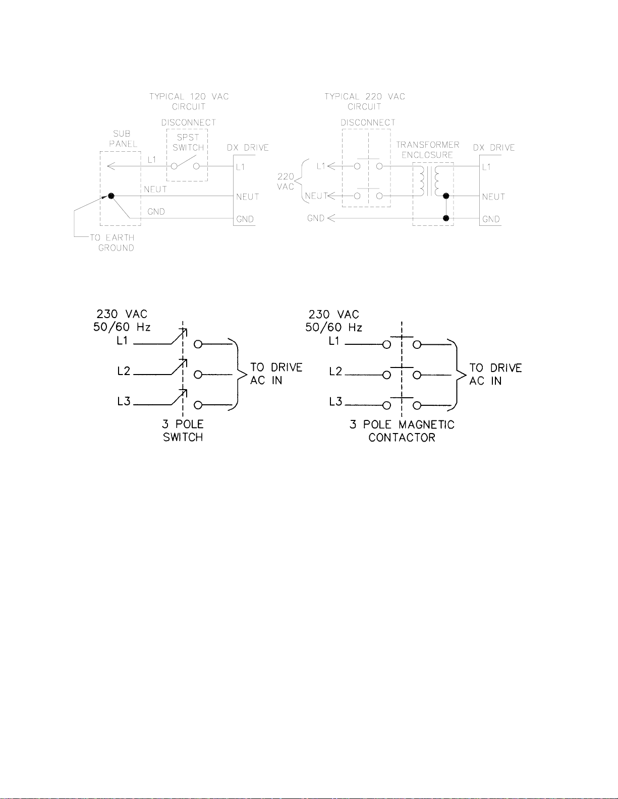
The following two circuits are given as EMC recommended external disconnecting examples for
the 120 VAC low power drives.
Figure 13 External Disconnect Examples (120 VAC Low Power)
The following examples are for the 230 VAC models. (DX-6XXX’s & DX-8XXX’s)
Figure 14 External Disconnect Examples (230 VAC High Power)
- 24 -
Artisan Technology Group - Quality Instrumentation ... Guaranteed | (888) 88-SOURCE | www.artisantg.com

Electrical Noise
Effects of electrical noise on the electronic equipment are greatly reduce when the techniques
outlined below are closely followed.
1. Do not run low power control signals and high power wiring in the same raceway.
NOTE: If mixing wire cannot be avoided, then the low voltage control input and output
wiring must be shielded. The shield for these wires should only be connected to ground only
at the source end of the signals.
2. Never connect both ends of a shielded cable to ground. This may cause a ground loop
condition which could be very difficult to locate.
3. It is suggested that all the wires in the system be kept as short as possible.
Magnetic Coil Noise
In the case of DC relays, a diode is installed across the coil in a direction that will cause the
voltage transient to be dissipated through the diode.
Figure 15 Magnetic Coil Noise (DC Line)
In the case of AC coils a capacitor and resistor are installed across the coil to supress the
unwanted transient.
Figure 16 Magnetic Coil Noise (AC Line)
The specific values of resistance and capacitance may vary depending on the inductance of the
coil. Consult the relay manufacturer for the proper values to use. These suppressor networks
greatly extend the life of the contacts controlling the coil because the transient energy, which can
easily reach 1000 volts, shunts through the suppressor’s rather than arcing across the controlling
contacts as they open.
- 25 -
Artisan Technology Group - Quality Instrumentation ... Guaranteed | (888) 88-SOURCE | www.artisantg.com

Mechanical Consideration
To provide good mechanical alignment the mounting surface of the motor face plate is held
perpendicular to the motor shaft to within 0.005 inches of the motor shaft. Projecting above the
plane of the mounting surface is a close tolerance circular pilot boss, which, when matched with
a pilot hole in the mounting structure, facilitates interchanging the motor, and minimizes the
need for mechanical adjustments. The mounting surface is fitted with four holes, equally spaced
on a bolt circle pattern.
The mounting panel must be stiff enough so it does not deflect significantly when radial loads
are applied to the motor shaft. The mounting panel should also have good thermal conductivity,
especially if peak performance is demanded of the motor.
Mechanical shock to the motor case or shaft (e.g., from striking or dropping) must be avoided to
prevent damage to the motor. Possible results from striking or dropping include: Misalignment
of the resolver; damage to armature bearings; cracking of the motor case; unbonding or
demagnetization of the permanent magnets. Any of these would render the motor unserviceable.
Load Coupling
A flexible coupling must be used on the motor shaft to minimize mechanical stress due to radial
loads, axial loads and/or misalignment. Radial and axial loading cannot exceed specified values.
Table VIII Load Coupling
Motor Max Radial Load Max Axial Load
DXM-202 10 lbs** 8 lbs
DXM-205 10 lbs** 8 lbs
DXM-308 20 lbs** 15 lbs
DXM-318 20 lbs** 15 lbs
DX* -430 50 lbs** 20 lbs
DX* -450 50 lbs** 20 lbs
DX* -480 75 lbs** 40 lbs
DXM-780 150 lbs** 50 lbs
DXM-7120 150 lbs** 50 lbs
DXM-6120 150 lbs** 50 lbs
DXM-6200 150 lbs** 50 lbs
DXM-6300 150 lbs** 50 lbs
DXM-8200 150 lbs** 50 lbs
DXM-8300 150 lbs** 50 lbs
DXM-8400 150 lbs** 50 lbs
* M-(XXX) = Metric E –(XXX) = English
** Maximum radial load is rated at 1 inch from the motor face
Gear Reduce Oil
It is strongly suggested that a synthetic oil is used in the gear reducer or rotary tables. This will
reduce the amount of current it takes to drive the motor.
- 26 -
Artisan Technology Group - Quality Instrumentation ... Guaranteed | (888) 88-SOURCE | www.artisantg.com

Selecting An Enclosure
The EMERSON EMC Positioning Drive is designed for the industrial environment. However,
no sophisticated electronic system can tolerate certain atmospheric contaminants such as
moisture, oils, conductive dust and metallic particles. Therefore, if the drive is going to be
subjected to this type of environment, we strongly urge you to mount your drive in a NEMA type
12 enclosure. Proper ventilation and filtering should also be provided. Amplifier losses should
be considered for enclosure sizing and ventilation.
Amplifier Losses
The exact power losses in any application depend on the application. The following table losses
would represent typical examples. The bridge power losses and shunt power losses can be
derated based on any duty cycle for power demand.
The logic supply power consumption varies based on PCM modules. For all 120 VAC models,
the logic power consumption is about 60 watts for the 230 VAC models. The consumption is
about 100 watts.
The next consideration would be bridge power losses which vary by amplifier size. The table
represents losses based on maximum continuous output current to the motor.
In applications where constant acceleration and deceleration occur, additional losses occur in the
shunt regulator where energy stored in the rotating inertia is commutated to the drives BUS
capacitors. This energy causes the BUS voltage to increase and once sensed, the excess voltage
is shorted through a load resistor. These losses could easily equal the bridge power losses.
Table IX Amplifier Losses (By Model)
Model Logic Supply Bridge Losses Shunt Losses Total
DXA-202 60W 10W 10W 80W
DXA-206 60W 25W 25W 110W
DXA-308 60W 45W 45W 150W
DXA-318 60W 100W 100W 260W
DXA-430 60W 130W 130W 320W
DXA-450 60W 200W 200W 460W
DXA-480 60W 340W 340W 740W
DXA-780 60W 340W 340W 740W
DXA-7120 60W 340W 340W 740W
DXA-6120 100W 400W 400W 900W
DXA-6200 100W 700W 700W 1500W
DXA-6300 100W 1000W 1000W 2100W
DXA-8200 100W 700W 700W 1500W
DXA-8300 100W 1000W 1000W 2100W
DXA-8400 100W 1500W 1500W 3100W
System Troubleshooting
If you encounter a system problem, double check the installation instructions. These instructions
eliminate most of the problems encountered. If you have a problem, call EMERSON EMC at
(612) 474-8833 and ask for Customer Service Department.
AMPLIFIER MOUNTING INFORMATION
- 27 -
Artisan Technology Group - Quality Instrumentation ... Guaranteed | (888) 88-SOURCE | www.artisantg.com
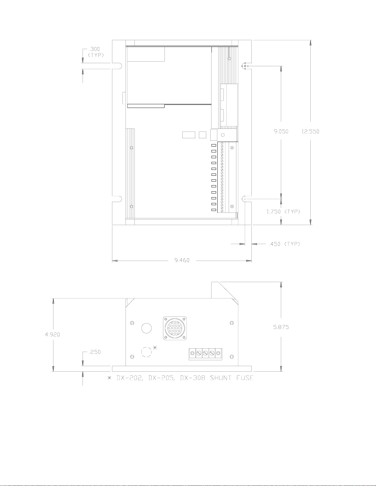
DX-202, DX-205, DX-308
Figure 17 Amplifier Mounting Information (DX-202, DX-205, DX-308)
- 28 -
Artisan Technology Group - Quality Instrumentation ... Guaranteed | (888) 88-SOURCE | www.artisantg.com
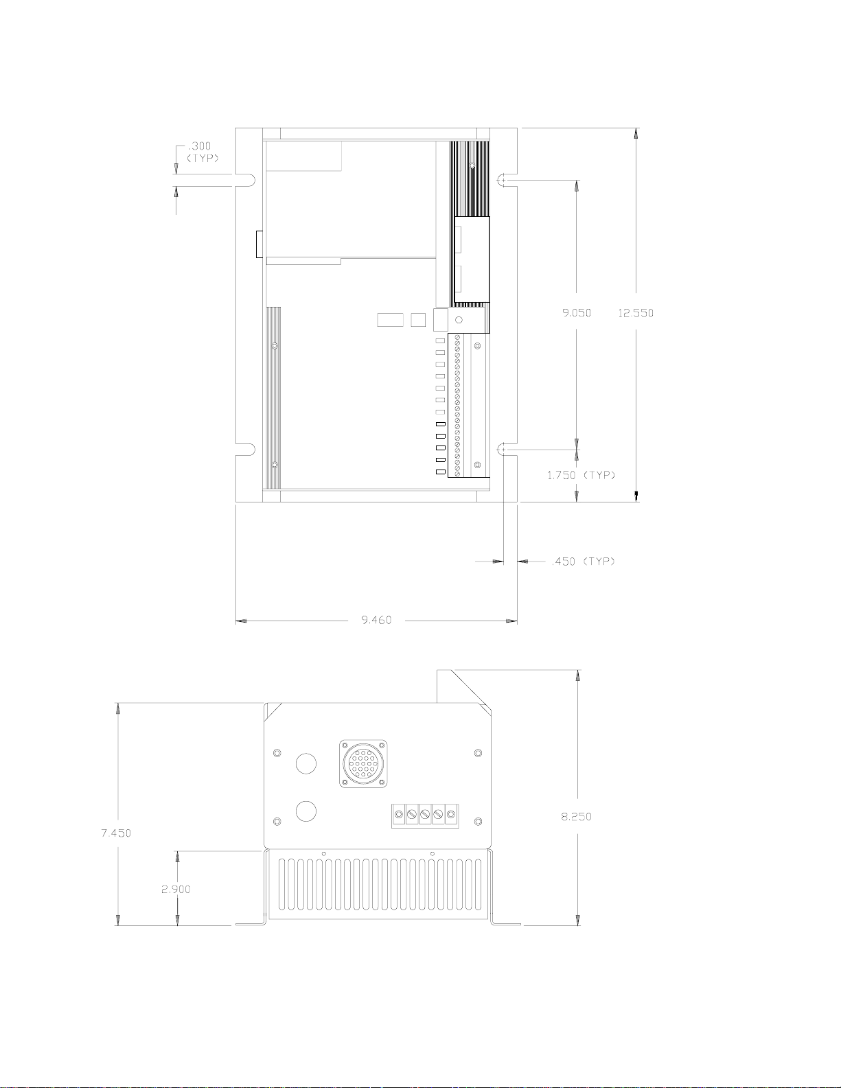
DX-318, DX-430, DX-450
Figure 18 Amplifier Mounting Information (DX-318, DX-430, DX-450)
- 29 -
Artisan Technology Group - Quality Instrumentation ... Guaranteed | (888) 88-SOURCE | www.artisantg.com
 Loading...