


Artisan Technology Group is your source for quality
new and certied-used/pre-owned equipment
• FAST SHIPPING AND
DELIVERY
• TENS OF THOUSANDS OF
IN-STOCK ITEMS
• EQUIPMENT DEMOS
• HUNDREDS OF
MANUFACTURERS
SUPPORTED
• LEASING/MONTHLY
RENTALS
• ITAR CERTIFIED
SECURE ASSET SOLUTIONS
SERVICE CENTER REPAIRS
Experienced engineers and technicians on staff
at our full-service, in-house repair center
Instra
Remotely inspect equipment before purchasing with
our interactive website at www.instraview.com
Contact us: (888) 88-SOURCE | sales@artisantg.com | www.artisantg.com
SM
REMOTE INSPECTION
View
WE BUY USED EQUIPMENT
Sell your excess, underutilized, and idle used equipment
We also offer credit for buy-backs and trade-ins
www.artisantg.com/WeBuyEquipment
LOOKING FOR MORE INFORMATION?
Visit us on the web at www.artisantg.com for more
information on price quotations, drivers, technical
specications, manuals, and documentation

EMERSON EMC
POSITIONING DRIVES & MOTORS
- - -
Including IOM-1, PCM-1, PCM-5
T-16, Thumbwheels, and Parallel Programming
Other Manuals available, but bound separately:
T-21 Data Entry Panel
Information furnished by EMERSON EMC is believed to be
accurate and reliable. However, no responsibility is assumed
by MERSON EMC for its use. EMERSON EMC reserves the
right to change the design or operation of the equipment
described herein and any associated motion products without
notice. EMERSON EMC also assumes no responsibility for
any errors that may appear in this document. Information in
this document is subject to change without notice.
P/N 400221-00 REV: A7
DATE: 6/24/92
- 1 -
Artisan Technology Group - Quality Instrumentation ... Guaranteed | (888) 88-SOURCE | www.artisantg.com

TABLE OF CONTENTS
INTRODUCTION....................................................................................................................................................... 6
OVERVIEW ............................................................................................................................................................. 6
S
YSTEM OVERVIEW ................................................................................................................................................... 7
I
NTRODUCTION TO THE BASIC POSITIONING DRIVE AMPLIFIER ................................................................................... 8
P
ERIPHERALS ............................................................................................................................................................. 9
O
PERATOR INTERFACE............................................................................................................................................. 10
T-21 D
ATA ENTRY TERMINAL ................................................................................................................................. 10
T-16 N
UMERIC DISPLAY.......................................................................................................................................... 10
TW-XXX T
POSITIONING DRIVE SPECIFICATIONS......................................................................................................... 12
DX-SERIES MOTORS AND AMPLIFIERS TYPICAL SPEED TORQUE CURVES ........................................ 15
INSTALLATION...................................................................................................................................................... 17
ASSEMBLY AND INSTALLATION CONSIDERATIONS ................................................................................ 17
TYPICAL 120 VAC LINE SIZING (SINGLE PHASE MODELS)....................................................................... 18
TYPICAL 230 VAC 3 PHASE MODELS.............................................................................................................. 19
AMPLIFIER MOUNTING INFORMATION ........................................................................................................ 27
AMPLIFER I/O LOCATIONS............................................................................................................................... 32
MOTOR MECHANICAL INFORMATION.......................................................................................................... 36
MOTOR WIRING .................................................................................................................................................. 43
MAIN/AUXILIARY AX
CABLE WIRING DIAGRAMS.............................................................................................................................. 48
HUMBWHEEL INTERFACE...................................................................................................................... 10
Wiring Considerations .......................................................................................................................................................20
Safety Considerations ........................................................................................................................................................21
Brake Option......................................................................................................................................................................21
Power Line......................................................................................................................................................................... 21
Grounding Considerations .................................................................................................................................................23
Electrical Noise..................................................................................................................................................................25
Magnetic Coil Noise ..........................................................................................................................................................25
Mechanical Consideration..................................................................................................................................................26
Load Coupling ...................................................................................................................................................................26
Selecting An Enclosure......................................................................................................................................................27
Amplifier Losses................................................................................................................................................................ 27
System Troubleshooting ....................................................................................................................................................27
POWER ......................................................................................................................... 46
TDS/TDL CABLE.............................................................................................................................................................48
TDT Cable .........................................................................................................................................................................48
Optional Bulkhead Connectors ..........................................................................................................................................49
OPERATING MODES............................................................................................................................................. 50
MODE SELECTION .............................................................................................................................................. 51
POSITIONING DRIVE CONFIGURATION AND PROGRAMMING ............................................................. 57
How To Start......................................................................................................................................................................58
PCX Program Revision...................................................................................................................................................... 58
Moving Through The Menus .............................................................................................................................................58
Changing Values In The Data Enter Screens .....................................................................................................................58
USING PCX DISK FILES...................................................................................................................................... 59
1. Data File........................................................................................................................................................................59
2. List File.........................................................................................................................................................................59
On-line Operations.............................................................................................................................................................60
ESTABLISHING COMMUNICATIONS .............................................................................................................. 62
DISK FILE OPERATIONS .................................................................................................................................... 63
DRIVE SETUP ....................................................................................................................................................... 64
LIMITS ................................................................................................................................................................... 68
INDEXING OPERATION MODE......................................................................................................................... 70
JOG ......................................................................................................................................................................... 75
HOME..................................................................................................................................................................... 76
OVERVIEW OF BASIC OPERATION MODES.................................................................................................. 84
Serial Mode........................................................................................................................................................................84
- 2 -
Artisan Technology Group - Quality Instrumentation ... Guaranteed | (888) 88-SOURCE | www.artisantg.com

Output Functions................................................................................................................................................................87
Input Functions ..................................................................................................................................................................88
DIAGNOSTICS......................................................................................................................................................... 98
F -POSITION ERROR FAULT............................................................................................................................ 100
FAULT INDICATOR CODES............................................................................................................................. 101
STABILIZATION OF HIGH INERTIA LOADS ................................................................................................ 106
INSTALLATION OF THE IOM-1 ....................................................................................................................... 107
INPUT/OUTPUT INTERFACE ........................................................................................................................... 108
Output Functions..............................................................................................................................................................110
Input Functions ................................................................................................................................................................111
EXAMPLES OF I/O CONNECTIONS TO THE IOM-1 ..................................................................................... 112
Detailed Description of Additional I/O Functions With the Addition of the IOM-1........................................................113
Input Functions ................................................................................................................................................................113
Output Function ...............................................................................................................................................................113
PARALLEL INTERFACE .................................................................................................................................... 114
CUSTOMER SUPPLIED THUMBWHEEL INTERFACE ................................................................................. 115
Thumbwheel Wiring........................................................................................................................................................116
PARALLEL PROGRAMMING INTERFACE ................................................................................................... 123
THUMBWHEEL AND PARALLEL PROGRAMMING SETUP AND OPERATION................................... 129
THUMBWHEEL AND PARALLEL PROGRAMMING INTERFACE ............................................................. 129
DATA FIELD NUMBER ................................................................................................................................................129
DATA FIELD PURPOSE................................................................................................................................................130
INDEX NUMBER ................................................................................................................................................ 131
T-16 SETUP AND OPERATION ........................................................................................................................ 136
INSTALLATION AND CONNECTIONS OF THE PCM-1 ............................................................................... 138
INPUT/OUTPUT INTERFACE (PCM-1)............................................................................................................ 139
OVERVIEW ......................................................................................................................................................... 139
O
UTPUT FUNCTIONS .............................................................................................................................................. 141
WHAT ARE PROGRAMS?................................................................................................................................. 147
DESCRIPTION OF PROGRAMMING FUNCTIONS ........................................................................................ 149
WAIT FOR INPUT..........................................................................................................................................................149
DWELL TIME.................................................................................................................................................................149
UPDATE OUTPUTS.......................................................................................................................................................149
EXECUTE INDEX..........................................................................................................................................................149
EXECUTE PROGRAM...................................................................................................................................................149
EXECUTE COMPOUND INDEX ..................................................................................................................................149
END .................................................................................................................................................................................149
HOW TO CREATE A PROGRAM...................................................................................................................... 151
PROGRAMMING CAPABILITIES .................................................................................................................... 154
SUSPEND/RESUME FUNCTIONS...................................................................................................................... 155
E
XTENDED SUSPEND/RESUME PROGRAMMING...................................................................................................... 156
INSTALLATION AND CONNECTIONS OF PCM-5........................................................................................ 158
SYNCHRONIZATION CABLE........................................................................................................................... 159
SCS-2 SYNC
ENCODER..................................................................................................................................... 161
BASIC OPERATION ........................................................................................................................................... 162
Some Application Examples............................................................................................................................................162
BI-POLAR SYNCHRONIZATION ..................................................................................................................... 168
ADDITIONAL PCM-5 PROGRAMMING .......................................................................................................... 177
PARAMETERS .................................................................................................................................................... 177
LEAD AXIS.......................................................................................................................................................... 177
SYNC RATIO....................................................................................................................................................... 177
SYNC VELOCITY SCALE FACTOR AND SYNC VELOCITY DECIMAL POINT ....................................... 178
BI-POLAR SYNC ENABLED............................................................................................................................. 179
INDEX, HOME .................................................................................................................................................... 179
PROGRAMS......................................................................................................................................................... 180
- 3 -
Artisan Technology Group - Quality Instrumentation ... Guaranteed | (888) 88-SOURCE | www.artisantg.com

SERIAL INTERFACE ........................................................................................................................................... 182
EXAMPLE OF A SERIAL MULTI-DROP CONNECTION............................................................................... 183
SERIAL SIGNAL FLOW DIAGRAMS............................................................................................................... 183
SETTING UP THE SERIAL INTERFACE SWITCHES AND PROTOCOL ..................................................... 184
LOCATIONS OF SWITCHES ............................................................................................................................. 184
SERIAL CABLES ................................................................................................................................................ 186
Wiring Diagrams From Computer to Drive .....................................................................................................................186
Wiring Diagram for DD-XXX Multi-Drop Cable............................................................................................................187
SERIAL INTERFACE CONTROL...................................................................................................................... 188
ASCII COMMANDS............................................................................................................................................ 189
SUMMARY OF SERIAL COMMANDS.............................................................................................................. 210
INDEX...................................................................................................................................................................... 216
- 4 -
Artisan Technology Group - Quality Instrumentation ... Guaranteed | (888) 88-SOURCE | www.artisantg.com

CUSTOMER SERVICE
Emerson EMC offers a wide range of services to support our customers’ needs. Listed below are
some examples of these services.
SERVICE SUPPORT (612) 474-8833
Emerson Electronic Motion Control’s products are backed by a team of professionals who will
service your installation wherever it may be. Our Customer Service Center in Minneapolis,
Minnesota, is ready to help you solve these occasional problems over the telephone. It’s there, at
the Center, that we are available 24 hours a day for emergency service to help speed any problem
solving. Also, all hardware replacement parts, should they ever be needed, are available through
our customer service organization. Need on-site help? Emerson provides on-site service, in
most cases, the next day. Just call Emerson’s Customer Service Center when on-site service or
maintenance is required.
TRAINING SERVICES (612) 474-1116
Emerson EMC maintains a highly trained staff of instructors to familiarize customers with
Emerson Electronic Motion Controls and their applications. A number of courses are offered,
many of which can be taught in your plant upon request.
APPLICATION ENGINEERING (612) 474-1117
An experienced staff of factory Application Engineers provides complete customer support for
tough or complex applications. Our engineers offer you a broad base of experience and
knowledge of electronic motion control applications.
- 5 -
Artisan Technology Group - Quality Instrumentation ... Guaranteed | (888) 88-SOURCE | www.artisantg.com

INTRODUCTION
OVERVIEW
The EMERSON EMC Positioning Drives are the first servo products specifically designed to
offer high performance position control without the maze of boards, wires, connectors, pot
adjustments and transformers normally associated with servo systems. The DX-Series drives
support brushless motors and range in size from 2 in-lbs. To 400 in-lbs., continuous. Special
care in motor selection has resulted in drives that have excellent torque to inertia ratios.
The drives consist of ruggedly constructed enclosures which contains all the required
components for position and velocity control. The drives also provide connections for
interfacing with external machine inputs and outputs, and logic control, along with a serial
interface port that is used to program the drive.
Calibration
Calibration of the Positioning Drive is virtually eliminated because all user potentiometer
adjustments have been eliminated. The potentiometer adjustments have been replaced by
firmware. The software pre-sets the compensation values and continuously adjusts these values
during motion. This allows the system to operate over a large inertial range without any manual
adjustments or tuning required.
Installation
Installation and wiring is fast and easy because the Positioning Drive operates in most
environments directly from an AC line source without requiring a separate isolation transformer.
The unit is designed to be back mounted within a standard Nema enclosure typically found in a
production facility. The size has also been minimized to allow users to reduce the space
requirements for incorporating a servo control into their production machinery.
Motor
Each Positioning Drive includes a high performance servo motor whose characteristics have
been matched to the drive amplifier. Thus, the chance for a mismatch between the motor and the
Positioning Drive is eliminated.
Programming and Troubleshooting
EMERSON EMC provides an easy to use software programming package with every drive that
operates on an IBM PC/XT/AT or compatible computer with 512K bytes of RAM and a serial
interface port. This software makes the Positioning Drive simple to program even for first time
servo users. It is almost essential that the user of the positioning servo drive have access to a
personal computer (PC). The PC can be used to change data, up and down load data and most
importantly, help solve problems during operation and startup.
- 6 -
Artisan Technology Group - Quality Instrumentation ... Guaranteed | (888) 88-SOURCE | www.artisantg.com

System Overview
Following are the specific model numbers used in configuring the Positioning Drives.
Table I Positioning Drive Components
DX-202 (2 in-lbs.) DXA-202 Amplifier
DXM-202 Motor
TDT-XX Cable
DX-205 (5 in-lbs.) DXA-205 Amplifier
DXM-202 Motor
TDT-XX Cable
DX-308 (8 in-lbs.) DXA-308 Amplifier
DXM Motor
TDL-XX Cable
DX-318 (18 in-lbs.) DXA-318 Amplifier
DXM Motor
TDL-XX Cable
DX-430 (30 in-lbs.) DXA-430 Amplifer
DXM or DXE-430 Motor*
TDL-XX Cable
DX-450 (50 in-lbs.) DXA-450 Amplififer
DXM or DXE-430 Motor*
TDL-XX Cable
DX-480 (80 in-lbs.) DXA-480 Amplifier
DXM or DXE-480 Motor*
TDL-XX Cable
DX-780 (80 in-lbs.) DXA-780 Amplifier
DXM-780 Motor
TDL-XX Cable
DX-7120 (120 in-lbs.) DXA-7120 Amplifier
DXM-7120 Motor
TDL-XX Cable
DX-6120 (120 in-lbs.) DXA-6120 Amplifier
DXM-6120 Motor
RC-XX Cable
DX-6200 (300 in-lbs.) DXA-6200 Amplifier
DXM-6200 Motor
RC-XX Cable
DX-6300 (300 in-lbs.) DXA-6300 Amplifier
DXM-6300 Motor
RC-XX Cable
DX-8200 (200 in-lbs.) DXA-8200 Amplifier
DXM-8200 Motor
DX-8300 (300 in-lbs.)
DX-8400 (400 in-lbs.) DXA-8400 Amplifier
NOTE: The DX-8XXX series motor and Amplifiers are interconnected Via screw terminals so as to
allow for customer provided wiring Not to exceed 100ft.
NOTE: XX = CABLE LENGTH (FT)15
25 25
50 50
*NOTE: DX-430, DX-450 and DX-480 Drives can be provided with Motors that have either typical
English or metric flange and Shaft dimensions. The metric motor is designated with a DXM
prefix and the English version is designated with a DXE prefix.
DXA-8300 Amplifier
DXM-8300 Motor
DXM-8400 Motor
- 7 -
Artisan Technology Group - Quality Instrumentation ... Guaranteed | (888) 88-SOURCE | www.artisantg.com

Introduction to the basic positioning drive amplifier
The Positioning Drive amplifier is different from common analog amplifiers in that it includes a
position feedback loop and the electronics to control motion functions. To accomplish this, the
motor uses resolver feedback. The resolver converter electronics in the amplifier develops
velocity and position feedback signals required for high performance and precise velocity and
position control.
In addition the amplifier offers three standard modes of control providing a host of alternatives
for implementing real time motion control.
In the ANALOG TORQUE or VELOCITY mode, the amplifier responds to a conventional +/10 volt signal. Most variable speed drives and servo amplifiers on the market today receive
commands via analog input.
The true power and versatility of the Positioning Drive is best utilized in the additional
positioning control modes. In most applications the user will use one of the following modes of
operation.
In the PULSE mode, the drive responds to a serial pulse train representing externally generated
incremental position change commands. These commands are normally in the form of CW or
CCW directional pulses. This mode is commonly used to control DC stepper motors or numeric
controlled (CNC) machinery.
The INDEXING mode allows up to thirty-two different indexes or positions to be preprogrammed and stored in a non-volatile memory. These indexes plus other commands such as
STOP and JOG are selected easily by the drive’s parallel input/output (I/O) lines from devices
such as PLCs or operator push buttons. Parallel I/O commands can be used for stand alone
operation or, simultaneously in conjunction with any other two control modes.
Another powerful feature of the INDEXING mode allows ASCII commands through the
standard RS423 serial interface. This interface port allows the user to down load new
dimensional data e.g., position, distance, velocity, etc., and command an internally generated
index using those parameters. These ASCII serial commands are well suited to operation from
the RS232C serial interface on an IBM Personal Computer (PC) or Programmable Logic
Controller (PLC) with ASCII or Basic Module.
For additional stand alone motion control capability, the drive is designed to accept a series of
application oriented modules called “PCM” modules. The PCMs can be attached to any drive by
simply plugging them onto the front. The PCM is designed to share the power supply inside of
the drive and includes 12 additional optically isolated inputs/outputs (making a total of 24).
When attached, the PCM module extends the operation of the Positioning Drive system.
The IOM-1, PCM-1, PCM-2 and PCM-5 modules are designed to be plug-on additions to
EMERSON EMC’s line of Positioning Drives. Each module is intended to enhance a specific
performance characteristic of the positioning drives.
- 8 -
Artisan Technology Group - Quality Instrumentation ... Guaranteed | (888) 88-SOURCE | www.artisantg.com

Peripherals
IOM-1 Input/Output Expander Module
The IOM Module mounts to the front of the basic drive to double the I/O capability for those
applications where the number of inputs and outputs provided with the basic unit are not
adequate for interfacing motion to the machine logic controllers. Each of these lines are
optically isolated and can be connected in either a current sinking or current sourcing
arrangement. In addition, the IOM-1 includes the parallel interface port required for connecting
1 or 2 thumbwheels and 1 remote display or parallel communications with a PLC.
PCM-1
The PCM-1 module converts the basic Positioning Drive from a “smart” servo drive system with
indexing capabilities into a motion control system capable of executing numbered sequences of
indexes called motion programs. Each motion program combines basic indexes to achieve
complex motion profiles beyond what is possible with the basic drive. In addition, the PCM
module greatly increases the non-volatile memory storage capability of the standard digital drive.
This allows the user greater flexibility in both the size and the number of programs (and indexes)
available. Another advantage of PCM-1 is that it increases the number of input lines from 8 to
16 and the number of output lines is increased from 4 to 8. All inputs and outputs are assignable
from a standard list of I/O functions. Lastly, the PCM-1 allows the user to create compound
indexes and includes the parallel interface port required for connecting 1 or 2 thumbwheels and 1
remote display or parallel communications with a PLC.
PCM-5
The PCM-5 has most of the capability of the PCM-1. The PCM-5 is able to do electronic
synchronized line shafting and ratio control. This is accomplished by using an external encoder
or drive representing a lead axis connected to the PCM-5. The drive with the PCM-5 can then be
synchronized to the lead device. This mode of operation also allows for pulse counting of the
lead device and indexing at velocities proportional to its speed. With this capability, flying
shear/cutoff applications can easily be configured.
- 9 -
Artisan Technology Group - Quality Instrumentation ... Guaranteed | (888) 88-SOURCE | www.artisantg.com

Operator Interface
Emerson EMC can provide three different peripheral devices to enhance the operator friendliness
of your drive. The T-21 Data Entry Terminal is ideally suited for providing machine operators
with the ability to enter and/or alter and display machine motion parameters controlled by
Emerson Digital Positioning Servo Drive. The T-16 displays position and velocity parameters
using large sized LEDs that are visible from several feet away. Emerson EMC offers a simple
thumbwheel interface called a TW-XXX that is offered in many different configurations. The
TW-XXX is used to change data of a specific motion parameter or parameters. The thumbwheel
option is ideal for applications needing minimum operator interface.
T-21 Data Entry Terminal
The T-21 communicates with any Emerson Positioning Drive using serial ASCII codes and
allows the machine designer to access, display, or alter certain motion parameters such as index
length. For frequently accessed motion parameters, the operator cam simply depress one of three
user programmable function switches located on the front panel. By depressing the correct
function key, the proper user created message is displayed. The message can be created to
include information as to what setup parameter is being changed, on which axis, etc. If more
than 3 operator altered setup parameters are required, a fourth F(x) key allows the user to store
up to 95 additional operator alterable setup functions.
T-16 Numeric Display
The T-16 is used to display position or velocity of the drive. The T-16 has 7 large LEDs that are
visible from several feet away. This allows the operator to view data shown on the display from
different positions on a machine. The T-16 requires the use of the ION-1 or a PCM-1 module.
The T-16 plugs into the parallel port on the module.
TW-XXX Thumbwheel Interface
The thumbwheel interface provides the user with a non-serial interface method for making
changes to specific motion functions. The user can set up the thumbwheel to change velocities,
distances/positions, dwell times, index counts, and acceleration and deceleration times. All the
thumbwheels are mounted in a small, self contained enclosure. Cables can be ordered in specific
lengths from 3 feet to 50 feet. The TW-XXX requires the user to have an IOM-1 or a PCM-1
module. The TW-XXX plugs into the parallel port on the module.
- 10 -
Artisan Technology Group - Quality Instrumentation ... Guaranteed | (888) 88-SOURCE | www.artisantg.com

FAMILY OF POSITIONING DRIVE PRODUCTS
Figure 1 Peripherals
Artisan Technology Group - Quality Instrumentation ... Guaranteed | (888) 88-SOURCE | www.artisantg.com
- 11 -

POSITIONING DRIVE SPECIFICATIONS
Specifications +/- 10%
Table II Positioning Drive Specifications
DRIVE PERFORMANCE
Drive Model#Motor
Model #
DX-202 DXM-202 2/4 .0000855 3000 7 AMP 2A(S.B.) 1.8 23 1.1/2.2
DX-205 DXM-205 5/10 .000253 3000 7 AMP 2A(S.B.) 1.8 23 3.0/6.0
DX-308 DXM-308 8/16 .0005 3000 7 AMP 2A(S.B.) 2.9 34 2.8/5.6
DX-318 DXM-318 18/36 .001 3000 10 AMP 5A(S.B.) 3.38 40 5.4/10.8
DX-430 DXM-430 30/60 .0026 3000 15 AMP 5A(S.B.) 3.38 40 8.9/17.8
DX-450 DXM-450 50/85 .0052 3000 25 AMP 5A(S.B.) 3.38 40 14.8/24.0
DX-480 DXM-480 80/160 .00772 3000 30 AMP 8A(S.B.) 3.36 42 24/48
DX-780 DXM-780 80/160 .013 3000 30 AMP 8A(S.B.) 3.38 40 24/48
DX-7120 DXM-7120 120/240 .021 2000 30 AMP 8A(S.B.) 5.57 66 24/48
DX-6120 DXM-6120 120/240 .0096 3000 15 AMP 7A 8 100 15/30
DX-6200 DXM-6200 200/400 .0192 3000 20 AMP 7A 8 100 25/50
DX-6300 DXM-6300 300/600 .0268 3000 30 AMP 10A 8 100 38/76
DX-8200 DXM-8200 200/300 .04 3000 20 AMP 7A 7.4 96 27/41
DX-8300 DXM-8300 300/450 .08 3000 30 AMP 10A 7.4 96 40/60
DX-8400 DXM-8400 400/600 .12 3000 40 AMP 10A 7.4 96 54/81
INPUT VOLTAGE: DX-202, DX-205, DX-308, DX-430, DX-450, DX-480, DX-780, DX-
INPUT VOLTAGE: DX-6120, DX-6200, DX-6300, DX-8200, DX-8300, DX-8400 = 196-
SWITCHING FREQUENCY: DX-202, DX-205, DX-308, DX-430 = 20 Khz
DEAD BAND: Zero
VELOCITY SIGNAL INPUT: ±10 vdc typical (10 bit resolution speed selection ±10 volt)
TORQUE SIGNAL INPUT: ± vdc typical (10 bit resolution speed selection ±10 volt)
PULSE MODE INPUT: TTL compatible, 500 nsec minimum pulse width, 210 Khz max
ANGULAR ACCURACY: Cable Length 15FT
USER UNITS/REV: Programmable Range (200-25000)
AMPLIFIER THERMAL SHUT DOWN AS DETECTED IN POWER STAGE:
All Drives: 80º - 90º C
MOTOR THERMAL SHUT DOWN AS DETECTED IN MOTOR (CASE TEMP):
All Motors: 100º - 115º C
Torque
Cont/Peak
IN/LBS
Rotor Interia
IN/LBS/SEC
Max. RPM Bus Fuse Shunt Fuse KT
IN-LBS/AMPKEVolts/KRPM
7120 = 96-132 VAC, 50/60 Hz, single phase
264 VAC 3 PHASE 50/60 Hz
DX-450, DX-480, DX-780, DX-7120 = 15 Khz
DX-6120, DX-6200 = 15 Khz
DX-6300 = 12 Khz
DX-8200, DX-8300, DX-8400 = 10 Khz
frequency
50FT 100FT
Minutes ±20 ±30 ±40
Amplifier
Current
Ratings
- 12 -
Artisan Technology Group - Quality Instrumentation ... Guaranteed | (888) 88-SOURCE | www.artisantg.com

OPTIONAL FAIL-SAFE BRAKE: (Activated by the Positioning Drive)
Table III Fail Safe Brake
Model Holding Torque
IN-LBS
DX-308 12
DX-318 25
DX-430 45
DX-450 75
DX-480 120
DX-780 120
DX-7120 180
DX-6120 400
DX-6200 400
DX-6300 400
*DX-8200 300
*DX-8300 450
*DX-8400 600
*Special (consult factory)
COMMAND PULSE: 5-15 vdc
MODE INPUTS: 25-70 milliamps
ANALOG INPUTS: -10 vdc to +10 vdc operating range
-12 vdc to +12 vdc absolute maximum
Different input greater than 9K ohms
SERIAL INTERFACE: RS423 signal compatible
Xmit, Rec, and GND
INPUTS AND OUTPUTS: Outputs: sink or source (2 terminals);
200 Ma max (external current limit required) each
Inputs: 10 to 30 vdc (internal current limit provided)
10, 12, 15 and 24 vdc typical
Table IV User Memory Capacity
User Memory Capacity
Drive
Drive
w/IOM-1
Jog 2 2 2 2
Home 1 1 1 1
Indexes 32 32 256 256
Programs 0 0 64 64
Drive
w/PCM-1
Drive
w/PCM-5
- 13 -
Artisan Technology Group - Quality Instrumentation ... Guaranteed | (888) 88-SOURCE | www.artisantg.com

Table V Number of User Programs
Number of Required
User Programs
1 1000
2 500
3 333
4 250
5 200
--
--
-62 16
63 15
Average Number of Available
Steps Per Program
Table VI Motor Load Specifications
Motor Radial and Axial Load Specifications
Motor Max Radial Load Max Axial Load
DXM-202 10 lbs 8 lbs
DXM-205 10 lbs 8 lbs
DXM-308 20 lbs 15 lbs
DXM-318 20 lbs 15 lbs
DX* -430 50 lbs 20 lbs
DX* -450 50 lbs 20 lbs
DX* -480 75 lbs 40 lbs
DXM-780 150 lbs 50 lbs
DXM-7120 150 lbs 50 lbs
DXM-6120 150 lbs 50 lbs
DXM-6200 150 lbs 50 lbs
DXM-6300 150 lbs 50 lbs
DXM-8200 150 lbs 50 lbs
DXM-8300 150 lbs 50 lbs
DXM-8400 150 lbs 50 lbs
- 14 -
Artisan Technology Group - Quality Instrumentation ... Guaranteed | (888) 88-SOURCE | www.artisantg.com
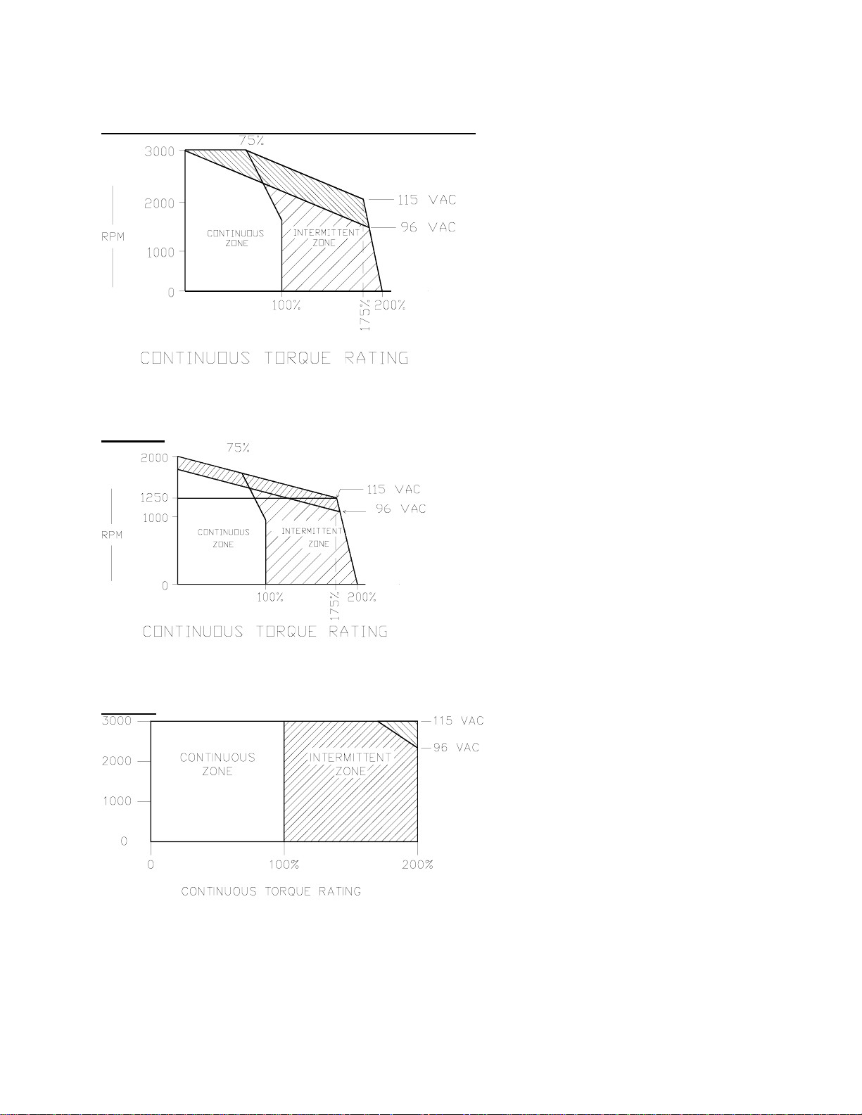
DX-SERIES MOTORS AND AMPLIFIERS TYPICAL SPEED
TORQUE CURVES
DX-202, DX-308, DX-318, DX-430, DX-480, DX-780
Figure 2 Typical Speed Torque Curve
DX-7120
Figure 3 Typical Speed Torque Curve
DX-205
Figure 4 Typical Speed Torque Curve
∗ Continuous torque rating of the motors is measured using a 10” X 10” X 0.25” mounting plate that
acts as a heatsink.
∗ All specifications are ± 10%.
- 15 -
Artisan Technology Group - Quality Instrumentation ... Guaranteed | (888) 88-SOURCE | www.artisantg.com
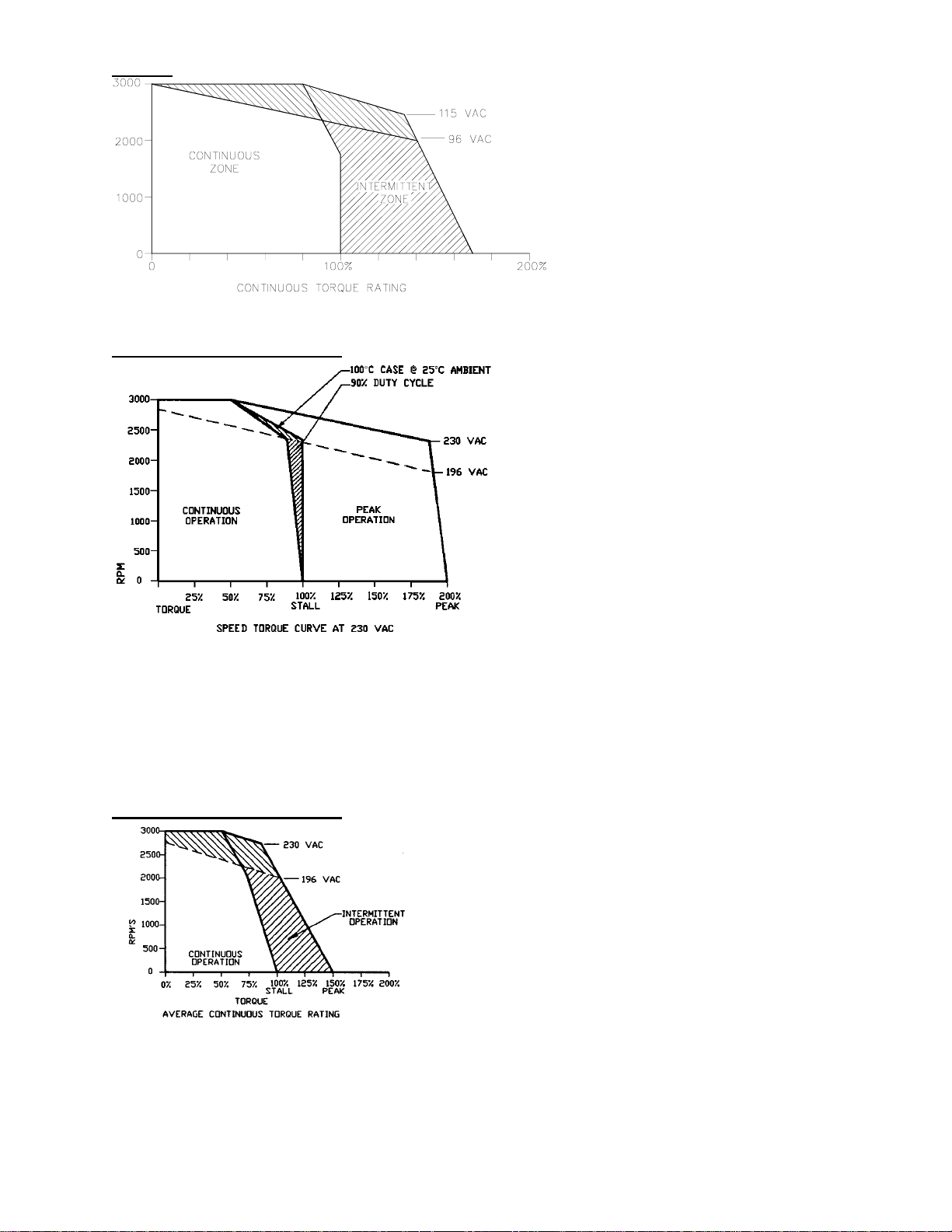
DX-450
Figure 5 Typical Speed Torque Curve
DX-6120, DX-6200, DX-6300
Figure 6 Typical Speed Torque Curve
1) Peak operation is available for ≥1.0 seconds from 0 torque.
2) Speed torque curves are based on 144” sq. by ½” thick aluminum face plate.
3) Derate available torque by 1% per °C for operation above 30°C, to an ambient temperature of
45°C, for motor and amplifier.
DX-8200, DX-8300, DX-8400
Figure 7 Typical Speed Torque Curve
∗ Continuous torque rating of the motors is measured using a 10” X 10” X 0.25” mounting plate that
acts as a heatsink.
∗ All specifications are ± 10%.
Artisan Technology Group - Quality Instrumentation ... Guaranteed | (888) 88-SOURCE | www.artisantg.com
- 16 -

INSTALLATION
OVERVIEW
The Positioning Drives were designed with simple installation in mind. The Drive normally
back-mounts into a standard NEMA enclosure. Because of its small footprint and no need for
external transformers, boards and power supplies, the Positioning Drive saves significant panel
space and cost over alternative servo positioning systems. Wiring and connecting the drive is
equally simple. AC line power is connected via provided screw terminals. All 120 VAC models
use single phase 50/60 Hz power. All 230 VAC models use 3 phase 50/60 Hz power.
Inputs and outputs for control and status are wired to a 12 position, detachable terminal strip (this
also makes servicing easy). The RS423 serial interface used for setup, status and control can be
connected with a 9 pin D-type connector. The motor connections for the 120 VAC single phase
models are accomplished with factory supplied cable and mating connectors. The higher power
230 VAC 3 phase models are connected via screw terminals at the amplifier and motor. This
allows the user to supply his own wire.
The larger drive motors also have NPT pipe thread holes for metallic raceways. It is a
requirement that the stator wiring R, S, T be run in metallic raceways and 1-1/4” pipe conduit
holes are provided. The feedback wiring must be done by using shielded cabling with 100%
shielding via a foil shield and a braided shield.
ASSEMBLY AND INSTALLATION CONSIDERATIONS
The following procedures outline the methods necessary to assure reliable and trouble free
installation of the EMERSON EMC Positioning Drive.
- 17 -
Artisan Technology Group - Quality Instrumentation ... Guaranteed | (888) 88-SOURCE | www.artisantg.com
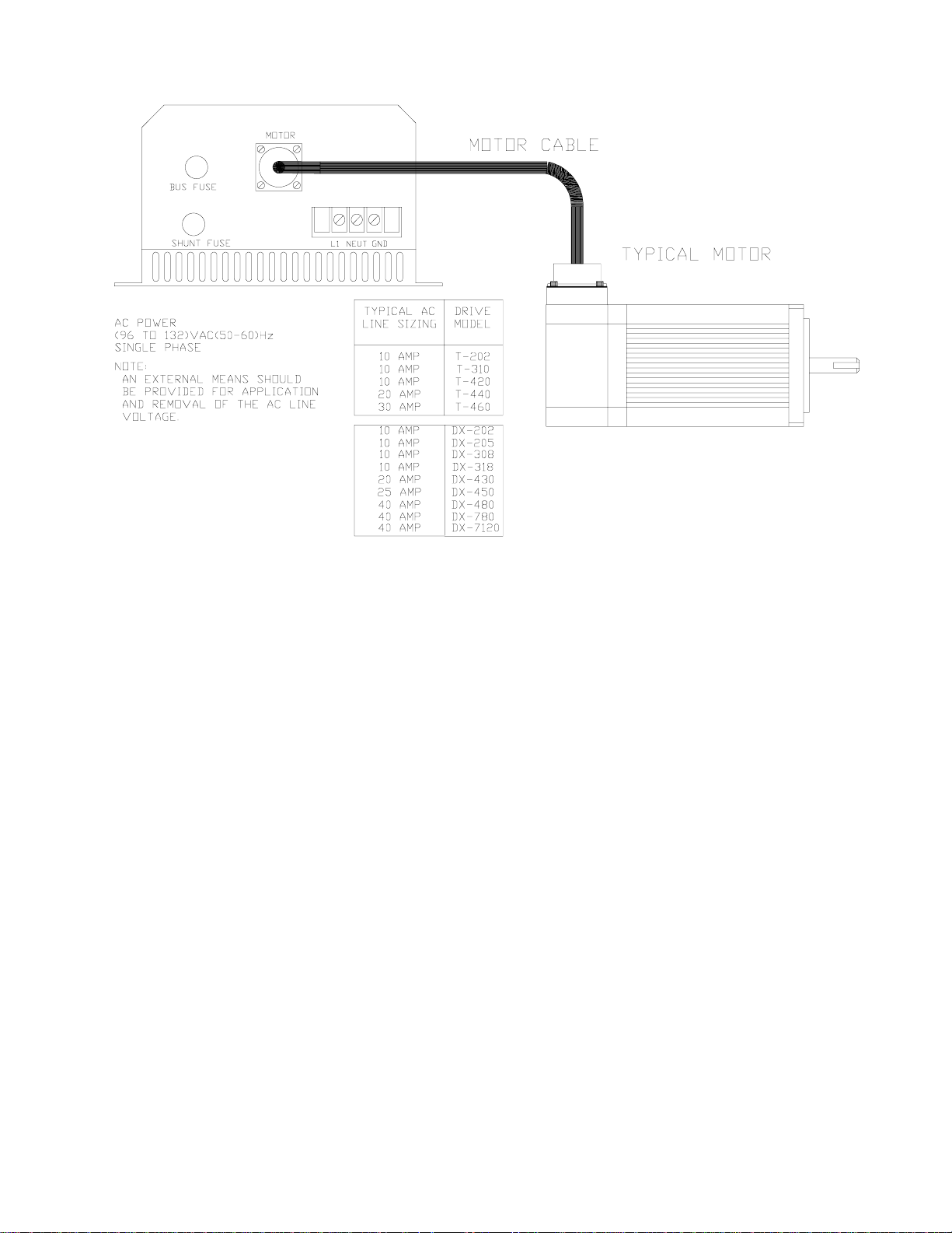
TYPICAL 120 VAC LINE SIZING (SINGLE PHASE MODELS)
Figure 8 Typical 120 VAC Line Sizing
The approximate AC line source VA rating can be determined by multiplying the AC line sizing
by 120 VAC.
Example: DX-780
Line sizing = 40 amp
(40 amps) ∗ (120 VAC) = 4800 VA
- 18 -
Artisan Technology Group - Quality Instrumentation ... Guaranteed | (888) 88-SOURCE | www.artisantg.com
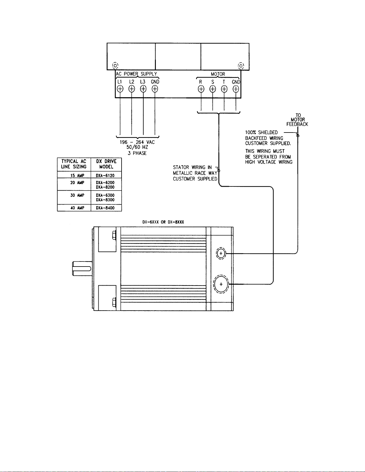
TYPICAL 230 VAC 3 PHASE MODELS
Figure 9 Typical 230 VAC 3 Phase Connections
The approximate AC line source VA rating can be determined by W = E•I 1.732
Example: DX-8200 = 20 Amps
Watts = 230 VAC • 20 Amps • 1.732 = 7,967
- 19 -
Artisan Technology Group - Quality Instrumentation ... Guaranteed | (888) 88-SOURCE | www.artisantg.com

The following table should be used as a guideline for minimum sizing the AC wiring.
Table VII Typical Line Ampacities & Wire Gauges
Drive Typical Line
Ampacities
DX-202 10 A 16 AWG
DX-205 10 A 16 AWG
DX-308 10 A 16 AWG
DX-318 10 A 16 AWG
DX-430 20 A 12 AWG
DX-450 25 A 12 AWG*
DX-480 40 A 10 AWG*
DX-780 40 A 10 AWG*
DX-7120 40 A 10 AWG*
DX-6120 15 A 12 AWG*
DX-6200 20 A 12 AWG*
DX-6300 30 A 10 AWG*
DX-8200 20 A 12 AWG*
DX-8300 30 A 10 AWG*
DX-8400 40 A 8 AWG*
Recommended
Minimum Wire Gauge
* AC power lines that are farther than 50 ft. from the power source, many require a larger gauge that
what is recommended above.
Wiring Considerations
If you are not sure of your grounding or signal wiring techniques, you should observe the
recommended practices according to the IEEE Ground Book, ANSI Standard C1141 and the
National Electric Code.
Wiring of any industrial equipment should be done with some consideration for future
troubleshooting and repair. All wiring should be either color coded or tagged with industrial
wire tabs.
All I/O wiring must be done with industrial grade insulated wire to withstand the environment of
the application. 18 to 24 gauge wire must be used for I/O wiring. The use of larger gauge wire
will cause the I/O terminals to prematurely fatigue. Each input and output to the control unit is
designed to have high noise immunity. This does not mean that high voltage, noise emitting
wiring on the rest of the application can be run adjacent to the control inputs. Precautions should
be taken to eliminate any possible noise from reaching the drive.
- 20 -
Artisan Technology Group - Quality Instrumentation ... Guaranteed | (888) 88-SOURCE | www.artisantg.com

Safety Considerations
The user is responsible for emergency interlock switches. Any master interlock should be wired
to shut down AC power to all parts of the system. Your system should be designed such that
power is disconnected from the output loads any time the equipment is not running, or when the
emergency stop is activated.
Brake Option
An additional safety and operational feature can be added by ordering the optional fail-safe
brake. The brake allows the motor shaft to be held whenever power is removed from the brake
coil (such as in a power failure). The user can control the on/off operation of the brake through
either serial commands or an assigned input line. The power supply needed to operate the brake
is provided internally in the drive.
Power Line
The lower power 120 VAC (DX-202 thru DX-7120) drives are designed to operate on a 50/60
Hz, single phase AC power line. The AC voltage of this power line must be within the specified
range of 96-132 VAC and be free of voltage transients which exceed this range. If it is found
that the AC power does not meet these specifications, further AC line conditioning may be
required. Also, if there is sensitive electronic equipment (digital computer, test equipment, etc.)
operating on the same AC power line as the Drive, additional EMI/RFI filtering may be required
to reduce the effects of conducted AC line noise. Operation at 96 VAC will reduce the drive’s
performance at high (max) speed.
The AC input lines are connected to the drive by means of the 3-position terminal strip located
on the bottom plate of the drive. The AC line wires should be connected as shown below.
Insufficient or incorrectly applied AC line power is a major cause of drive problems. Wiring
sizing and transformer selection (if necessary) should be done carefully.
CAUTION: To insure proper operation after a power down the user should wait a minimum of
10 seconds before reapplication of power.
Figure 10 Typical 120 VAC Drives
• L2 is the AC neutral wire and must be grounded (see “Grounding Considerations”.)
- 21 -
Artisan Technology Group - Quality Instrumentation ... Guaranteed | (888) 88-SOURCE | www.artisantg.com
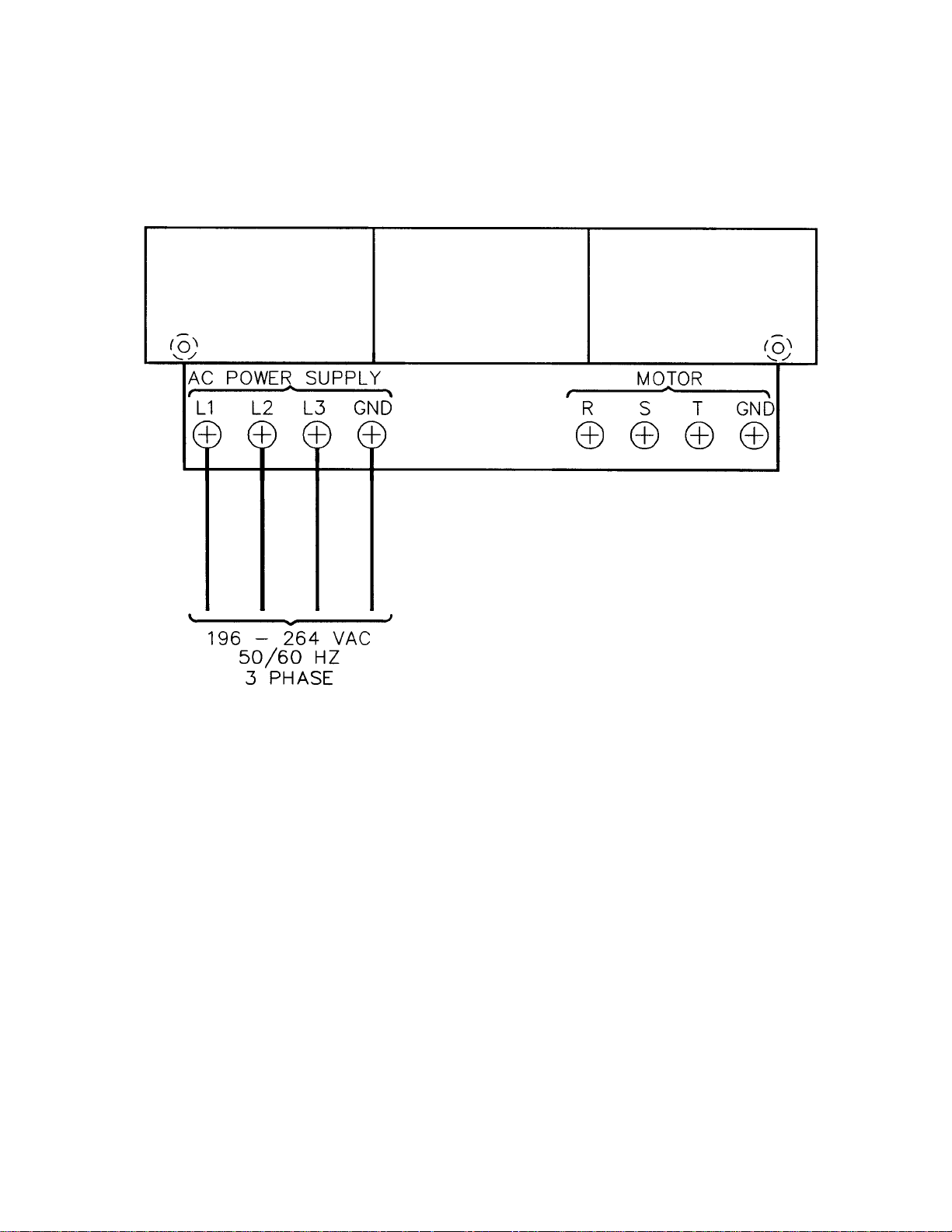
The high power 230 VAC (DX-6120, DX-6200, DX-6300, DX-8200, DX-8300, DX-8400) are
designed to operate on 3 phase AC power. The AC voltage for these drives must be between 196
to 264 VAC.
The AC input lines are connected to the drive by means of the 4 terminals located on the bottom
plate of the drive. The AC line wires should be connected as shown below. Insufficient AC line
power from wire size and control transformers is a major cause of drive problems.
Figure 11 Typical 230 VAC Drives
The GND terminal is bonded to the chassis and must be connected to earth ground.
- 22 -
Artisan Technology Group - Quality Instrumentation ... Guaranteed | (888) 88-SOURCE | www.artisantg.com
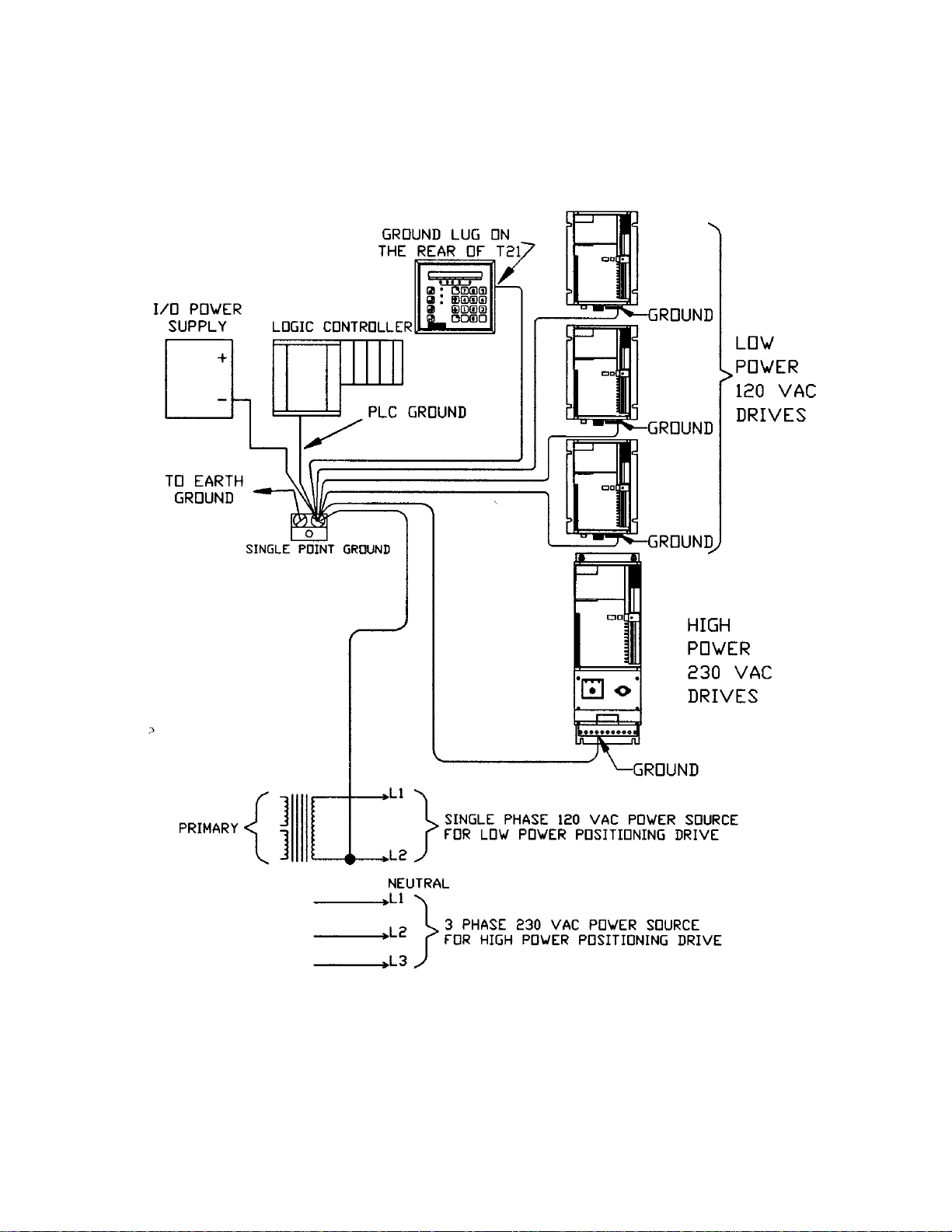
Grounding Considerations
The GND terminal of the drive is internally bonded to the frame. The enclosure ground and the
drive ground should be a common single point that ultimately is a continuous electrical path to
earth ground. The following example illustrates the ideal grounding arrangement of the AC
power.
Figure 12 Grounding Illustration
NOTE: These ground wires should not be shared with other equipment. Also note that the
neutral (L2) for the 120 VAC source for the low power positioning drive is grounded.
- 23 -
Artisan Technology Group - Quality Instrumentation ... Guaranteed | (888) 88-SOURCE | www.artisantg.com
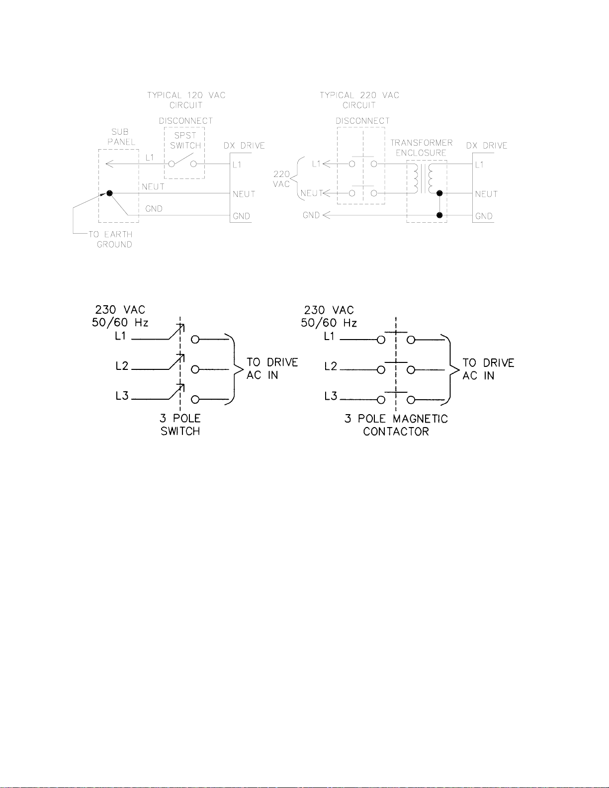
The following two circuits are given as EMC recommended external disconnecting examples for
the 120 VAC low power drives.
Figure 13 External Disconnect Examples (120 VAC Low Power)
The following examples are for the 230 VAC models. (DX-6XXX’s & DX-8XXX’s)
Figure 14 External Disconnect Examples (230 VAC High Power)
- 24 -
Artisan Technology Group - Quality Instrumentation ... Guaranteed | (888) 88-SOURCE | www.artisantg.com
Electrical Noise
Effects of electrical noise on the electronic equipment are greatly reduce when the techniques
outlined below are closely followed.
1. Do not run low power control signals and high power wiring in the same raceway.
NOTE: If mixing wire cannot be avoided, then the low voltage control input and output
wiring must be shielded. The shield for these wires should only be connected to ground only
at the source end of the signals.
2. Never connect both ends of a shielded cable to ground. This may cause a ground loop
condition which could be very difficult to locate.
3. It is suggested that all the wires in the system be kept as short as possible.
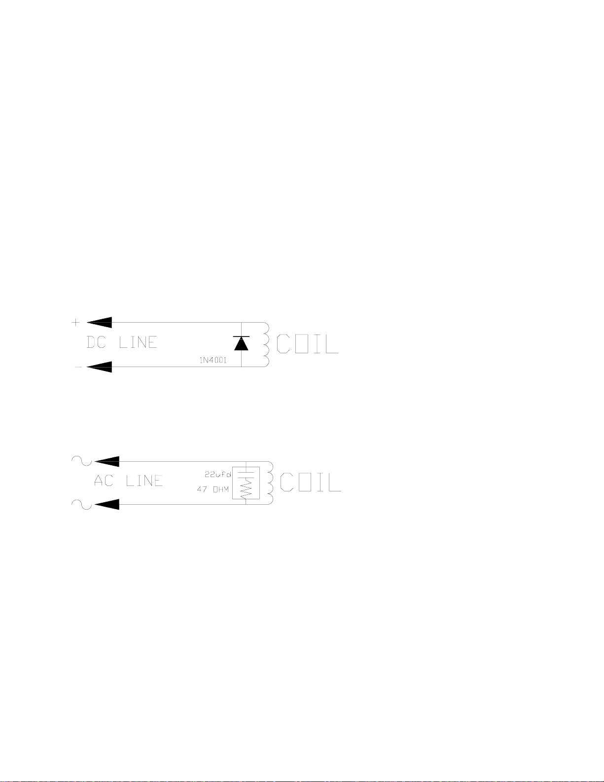
Magnetic Coil Noise
In the case of DC relays, a diode is installed across the coil in a direction that will cause the
voltage transient to be dissipated through the diode.
Figure 15 Magnetic Coil Noise (DC Line)
In the case of AC coils a capacitor and resistor are installed across the coil to supress the
unwanted transient.
Figure 16 Magnetic Coil Noise (AC Line)
The specific values of resistance and capacitance may vary depending on the inductance of the
coil. Consult the relay manufacturer for the proper values to use. These suppressor networks
greatly extend the life of the contacts controlling the coil because the transient energy, which can
easily reach 1000 volts, shunts through the suppressor’s rather than arcing across the controlling
contacts as they open.
- 25 -
Artisan Technology Group - Quality Instrumentation ... Guaranteed | (888) 88-SOURCE | www.artisantg.com

Mechanical Consideration
To provide good mechanical alignment the mounting surface of the motor face plate is held
perpendicular to the motor shaft to within 0.005 inches of the motor shaft. Projecting above the
plane of the mounting surface is a close tolerance circular pilot boss, which, when matched with
a pilot hole in the mounting structure, facilitates interchanging the motor, and minimizes the
need for mechanical adjustments. The mounting surface is fitted with four holes, equally spaced
on a bolt circle pattern.
The mounting panel must be stiff enough so it does not deflect significantly when radial loads
are applied to the motor shaft. The mounting panel should also have good thermal conductivity,
especially if peak performance is demanded of the motor.
Mechanical shock to the motor case or shaft (e.g., from striking or dropping) must be avoided to
prevent damage to the motor. Possible results from striking or dropping include: Misalignment
of the resolver; damage to armature bearings; cracking of the motor case; unbonding or
demagnetization of the permanent magnets. Any of these would render the motor unserviceable.
Load Coupling
A flexible coupling must be used on the motor shaft to minimize mechanical stress due to radial
loads, axial loads and/or misalignment. Radial and axial loading cannot exceed specified values.
Table VIII Load Coupling
Motor Max Radial Load Max Axial Load
DXM-202 10 lbs** 8 lbs
DXM-205 10 lbs** 8 lbs
DXM-308 20 lbs** 15 lbs
DXM-318 20 lbs** 15 lbs
DX* -430 50 lbs** 20 lbs
DX* -450 50 lbs** 20 lbs
DX* -480 75 lbs** 40 lbs
DXM-780 150 lbs** 50 lbs
DXM-7120 150 lbs** 50 lbs
DXM-6120 150 lbs** 50 lbs
DXM-6200 150 lbs** 50 lbs
DXM-6300 150 lbs** 50 lbs
DXM-8200 150 lbs** 50 lbs
DXM-8300 150 lbs** 50 lbs
DXM-8400 150 lbs** 50 lbs
* M-(XXX) = Metric E –(XXX) = English
** Maximum radial load is rated at 1 inch from the motor face
Gear Reduce Oil
It is strongly suggested that a synthetic oil is used in the gear reducer or rotary tables. This will
reduce the amount of current it takes to drive the motor.
- 26 -
Artisan Technology Group - Quality Instrumentation ... Guaranteed | (888) 88-SOURCE | www.artisantg.com

Selecting An Enclosure
The EMERSON EMC Positioning Drive is designed for the industrial environment. However,
no sophisticated electronic system can tolerate certain atmospheric contaminants such as
moisture, oils, conductive dust and metallic particles. Therefore, if the drive is going to be
subjected to this type of environment, we strongly urge you to mount your drive in a NEMA type
12 enclosure. Proper ventilation and filtering should also be provided. Amplifier losses should
be considered for enclosure sizing and ventilation.
Amplifier Losses
The exact power losses in any application depend on the application. The following table losses
would represent typical examples. The bridge power losses and shunt power losses can be
derated based on any duty cycle for power demand.
The logic supply power consumption varies based on PCM modules. For all 120 VAC models,
the logic power consumption is about 60 watts for the 230 VAC models. The consumption is
about 100 watts.
The next consideration would be bridge power losses which vary by amplifier size. The table
represents losses based on maximum continuous output current to the motor.
In applications where constant acceleration and deceleration occur, additional losses occur in the
shunt regulator where energy stored in the rotating inertia is commutated to the drives BUS
capacitors. This energy causes the BUS voltage to increase and once sensed, the excess voltage
is shorted through a load resistor. These losses could easily equal the bridge power losses.
Table IX Amplifier Losses (By Model)
Model Logic Supply Bridge Losses Shunt Losses Total
DXA-202 60W 10W 10W 80W
DXA-206 60W 25W 25W 110W
DXA-308 60W 45W 45W 150W
DXA-318 60W 100W 100W 260W
DXA-430 60W 130W 130W 320W
DXA-450 60W 200W 200W 460W
DXA-480 60W 340W 340W 740W
DXA-780 60W 340W 340W 740W
DXA-7120 60W 340W 340W 740W
DXA-6120 100W 400W 400W 900W
DXA-6200 100W 700W 700W 1500W
DXA-6300 100W 1000W 1000W 2100W
DXA-8200 100W 700W 700W 1500W
DXA-8300 100W 1000W 1000W 2100W
DXA-8400 100W 1500W 1500W 3100W
System Troubleshooting
If you encounter a system problem, double check the installation instructions. These instructions
eliminate most of the problems encountered. If you have a problem, call EMERSON EMC at
(612) 474-8833 and ask for Customer Service Department.
AMPLIFIER MOUNTING INFORMATION
- 27 -
Artisan Technology Group - Quality Instrumentation ... Guaranteed | (888) 88-SOURCE | www.artisantg.com
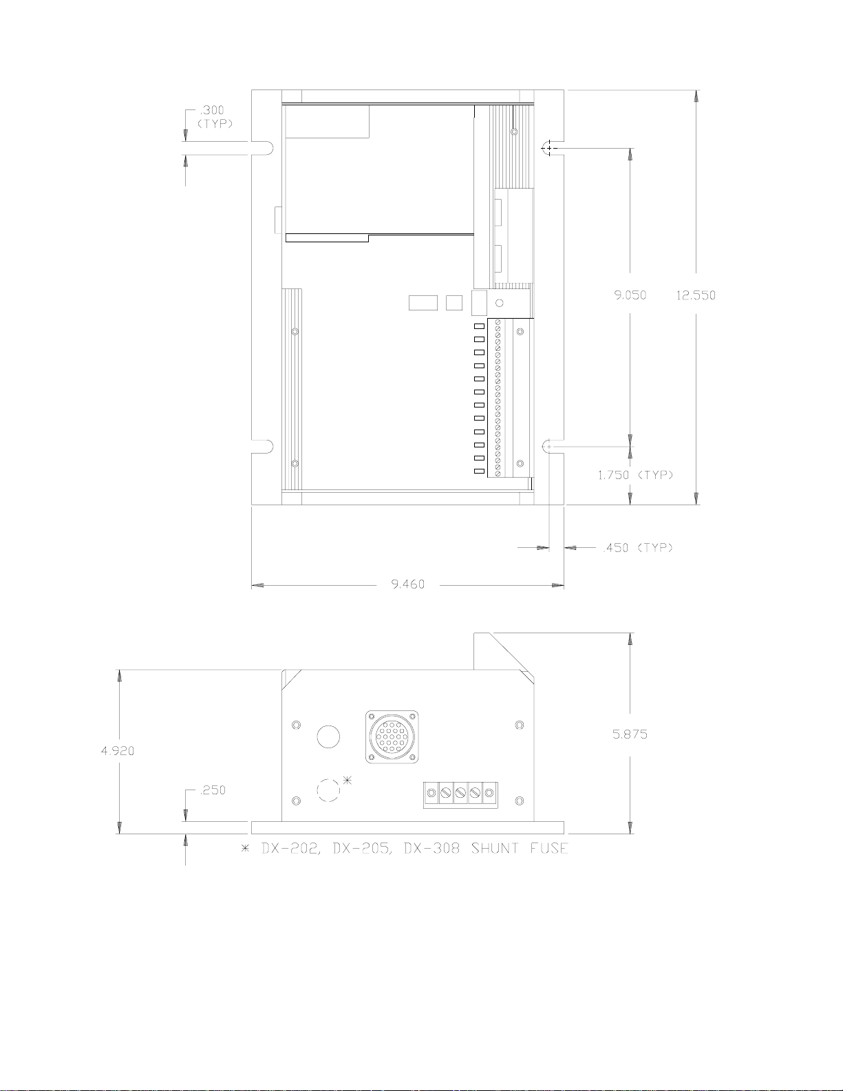
DX-202, DX-205, DX-308
Figure 17 Amplifier Mounting Information (DX-202, DX-205, DX-308)
- 28 -
Artisan Technology Group - Quality Instrumentation ... Guaranteed | (888) 88-SOURCE | www.artisantg.com
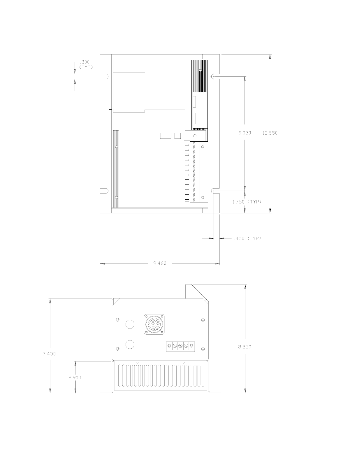
DX-318, DX-430, DX-450
Figure 18 Amplifier Mounting Information (DX-318, DX-430, DX-450)
- 29 -
Artisan Technology Group - Quality Instrumentation ... Guaranteed | (888) 88-SOURCE | www.artisantg.com

DX-480, DX-780, DX-7120
Figure 19 Amplifier Mounting Information (DX-480, DX-780, DX-7120)
- 30 -
Artisan Technology Group - Quality Instrumentation ... Guaranteed | (888) 88-SOURCE | www.artisantg.com

DX-6120, DX-6200, DX-6300, DX-8200, DX-8300, DX-8400
Figure 20 Amplifier Mounting Information (DX-8XXX, DX-6XXX)
CAUTION: These amplifiers cannot be mounted on a combustible surface, as a 1000 watt
shunt resistor is located in the base of the chassis. A metal back panel or no back
panel is preferred.
- 31 -
Artisan Technology Group - Quality Instrumentation ... Guaranteed | (888) 88-SOURCE | www.artisantg.com

AMPLIFER I/O LOCATIONS
DX-202, DX-205, DX-308
Figure 21 Amplifier I/O Locations (DX-202, DX-205, DX-308)
- 32 -
Artisan Technology Group - Quality Instrumentation ... Guaranteed | (888) 88-SOURCE | www.artisantg.com

DX-318, DX-430, DX-450
Figure 22 Amplifier I/O Locations (DX-318, DX-430, DX-450)
- 33 -
Artisan Technology Group - Quality Instrumentation ... Guaranteed | (888) 88-SOURCE | www.artisantg.com

DX-480, DX-780, DX-7120
Figure 23 Amplifier I/O Locations (DX-480, DX-780, DX-7120)
- 34 -
Artisan Technology Group - Quality Instrumentation ... Guaranteed | (888) 88-SOURCE | www.artisantg.com

DX-6120, DX-6200, DX-6300, DX-8200, DX-8300, DX-8400
Figure 24 Amplifier I/O Locations (DX-8XXX & DX-6XXX)
- 35 -
Artisan Technology Group - Quality Instrumentation ... Guaranteed | (888) 88-SOURCE | www.artisantg.com

MOTOR MECHANICAL INFORMATION
DXM-202, DXM-205
Figure 25 Motor Mechanical Information (DXM-202, DXM-205)
- 36 -
Artisan Technology Group - Quality Instrumentation ... Guaranteed | (888) 88-SOURCE | www.artisantg.com

DXM-308, DXM-318
Figure 26 Motor Mechanical Information (DXM-308, DXM-318)
- 37 -
Artisan Technology Group - Quality Instrumentation ... Guaranteed | (888) 88-SOURCE | www.artisantg.com

DXM-430, DXM-450, DXM-480
Figure 27 Motor Mechanical Information (DXM-430, DXM-450, DXM-480)
- 38 -
Artisan Technology Group - Quality Instrumentation ... Guaranteed | (888) 88-SOURCE | www.artisantg.com

DXE-430, DXE-450, DXE-480
Figure 28 Motor Mechanical Information (DXE-430, DXE-450)
- 39 -
Artisan Technology Group - Quality Instrumentation ... Guaranteed | (888) 88-SOURCE | www.artisantg.com

DXM-780, DXM-7120
Figure 29 Motor Mechanical Information (DXM-780, DXM-7120)
- 40 -
Artisan Technology Group - Quality Instrumentation ... Guaranteed | (888) 88-SOURCE | www.artisantg.com

DXM-6120, DXM-6200, DXM-6300
Figure 30 Motor Mechanical Information (DXM-6120, DXM-6200, DXM-6300)
- 41 -
Artisan Technology Group - Quality Instrumentation ... Guaranteed | (888) 88-SOURCE | www.artisantg.com

DXM-8200, DXM-8300, DXM-8400
Figure 31 Motor Mechanical Information (DXM-8200, DXM-8300, DXM-8400)
- 42 -
Artisan Technology Group - Quality Instrumentation ... Guaranteed | (888) 88-SOURCE | www.artisantg.com

MOTOR WIRING
DX* 308,318,430,450,480,780,7120
*English or metric motors.
The diagram below indicates how the motor, resolver, thermostat and optional brake are wired.
Figure 32 Motor Wiring (DX-308, DX-318, DX-430, DX-450, DX-480, DX-780, DX-7120)
- 43 -
Artisan Technology Group - Quality Instrumentation ... Guaranteed | (888) 88-SOURCE | www.artisantg.com

MOTOR WIRING – DXM 202, DXM-205
Figure 33 Motor Wiring (DXM-202, DXM-205)
- 44 -
Artisan Technology Group - Quality Instrumentation ... Guaranteed | (888) 88-SOURCE | www.artisantg.com

MOTOR WIRING – DXM 6120, DXM-6200, DXM-6300
Figure 34 Motor Wiring (DXM-6120, DXM-6200, DXM-6300)
- 45 -
Artisan Technology Group - Quality Instrumentation ... Guaranteed | (888) 88-SOURCE | www.artisantg.com

MAIN/AUXILIARY AC POWER
Figure 35 Motor/Amplifier Auxiliary Wiring
An external AC voltage of 220 VAC single phase can be connected to the AUX AX power input
to the appropriate terminals (L1, L2 and GND). The main/auxiliary switch can be switched to
the AUX position. Power for the logic supplies that power the computer is now separated from
the high power circuits that create the motor +BUS voltage. The high current and voltage can
now be removed from the three phase L1/L2/L3 and GND terminals, thus eliminating the DC
BUS supply voltage source for the motor. Under these conditions, the position feedback from
the resolver is in tact, yet high power voltage and current sources for R, S & T are removed.
Motor power reduces to nothing as the BUS capacitors discharge after AC power is removed
from the “MAIN AC POWER” input. An un-interruptible power supply of 220 VAC at 1 amp is
adequate for power to the auxiliary input.
- 46 -
Artisan Technology Group - Quality Instrumentation ... Guaranteed | (888) 88-SOURCE | www.artisantg.com

FEEDBACK WIRING – DXM-8200, DXM-8300, DXM-8400
Figure 36 Feedback Wiring (DX-8XXX’s)
- 47 -
Artisan Technology Group - Quality Instrumentation ... Guaranteed | (888) 88-SOURCE | www.artisantg.com

CABLE WIRING DIAGRAMS
TDS/TDL CABLE
Shown below is a diagram on how the interconnect cable from the Drive to motor is assembled.
Figure 37 Cable Wiring Diagram (TDS/TDL)
The DX-308 and DX-318 use cable model TDS-XX. The DX-430, DX-450, DX780, and DX7120 use model TDL-XX.
WHERE XX DESIGNATES LENGTH
XX = LENGTH (FT)
15 15
25 25
50 50
TDT Cable
Figure 38 Cable Wiring Diagram (TDT)
The DX-202, and DX-205 use cable model number TDT-XX
WHERE XX DESIGNATES LENGTH
XX = LENGTH (FT)
15 15
25 25
51 50
- 48 -
Artisan Technology Group - Quality Instrumentation ... Guaranteed | (888) 88-SOURCE | www.artisantg.com

Optional Bulkhead Connectors
Figure 39 Mounting Information, Bulkhead Connector, TDLB Cable
Figure 40 Mounting Information, Bulkhead Connector, TDTB Cable
- 49 -
Artisan Technology Group - Quality Instrumentation ... Guaranteed | (888) 88-SOURCE | www.artisantg.com

OPERATING MODES
OVERVIEW
The Positioning Drive is differentiated from common analog servo drives in that the amplifier
includes a position feedback loop. As a result, the amplifier will provide both precise position
and velocity control of the motor. The drive utilizes resolver feedback for both velocity and
position feedback. Thus, a tachometer is no longer required.
The drives include three different control modes providing alternatives for implementing motion
control. The modes are listed below.
Table X Motion Control Modes
MODE CONTROL INTERFACE COMMAND DEVICE
Analog Velocity Zero to +/- 10vdc Velocity Controller
Torque Zero to +/- 10vdc Torque Controller
Pulse Position
Increments
Position Increments CW & CCW Pulses Motion Generator,
Indexing Index, Home, Jog Inputs & Outputs 10 to
Index, Home, Job
and Motion
Programming
Pulse & Direction
+5 to +15V Logic
+30vdc, Optically Isolated
(sink or source)
RS423/422/232C Serial
Interface XMIT/REC ASCII
Motion Generator,
Indexer, CNC
Indexer, CNC
Relay Logic, Operator
Control Panel or a
Programmable Logic
Controller
Personal Computer, ASCII
Unit on PLC, ASCII
Terminal
- 50 -
Artisan Technology Group - Quality Instrumentation ... Guaranteed | (888) 88-SOURCE | www.artisantg.com

MODE SELECTION
There are basically three separate operating modes: ANALOG, PULSE FOLLOWER, and
INDEXING. The DIP switches 3 and 4 are used to help configure the operating modes. Units
are shipped with DIP switches 3 and 4 OFF.
Figure 41 Dipswitches/Mode Selection
Artisan Technology Group - Quality Instrumentation ... Guaranteed | (888) 88-SOURCE | www.artisantg.com
- 51 -

Analog Mode
In the Analog Torque or Velocity mode, the servo amplifier responds to a conventional ±10 volt
DC signal. Most variable speed drives and servo amplifiers on the market today receive
commands via this type of signal. If the DIP switches are set to enable this mode, the display
character of the digital drive will be an (A). In this mode, a ±10 volt command signal is equated
to ± velocity or peak torque as determined by the drives preprogrammed velocity (3000 RPM
default) or peak torque based on drive size. ±10 = ± peak torque. The external and serial control
modes are not ignored if an (A) is on the display. Sending an SC=1 to the drive would disable
analog control and enable serial control with an (E) being on the display. If an (A) was on the
display and an initiate index home or job from the I/O occurs, then the (A) will be replaced with
an (E) and the requested motion occurs. At the end of motion, the display and mode revert to
(A).
In either of the two analog modes of operation a (+)/(-) 10 VDC signal is equated to either (CW)
or (CCW) maximum programmed velocity in the velocity mode or CW or CCW full peak rating
in the torque mode. The mode of operation can be selected via the mode select switches on the
front of the servo drive.
NOTE: CW rotation is defined while facing the shaft end of the motor.
Figure 42 Velocity/Torque Mode
- 52 -
Artisan Technology Group - Quality Instrumentation ... Guaranteed | (888) 88-SOURCE | www.artisantg.com

In either mode the ±10 VDC command signal is connected to the command input. The input
circuit of the drive is a differential input amplifier with the following characteristics.
Application of a + voltage to pin 7 with respect to pin 13 (GRD) will produce either a CW
motion or torque in the CW direction as viewed from the shaft end of the motor.
Figure 43 Command Input Circuit
IMPORTANT: Voltages on pins 6 or 7 must not exceed ±12 VDC with respect to analog
ground.
Figure 44 Command Connector
To execute the Analog Mode, the mode select switches must be set correctly for either Analog
Velocity or Analog Torque control and apply ±10 volts DC to the command connector on the
amplifier.
REMINDER: Both the hardware and software position travel limits are active if they are set
up.
- 53 -
Artisan Technology Group - Quality Instrumentation ... Guaranteed | (888) 88-SOURCE | www.artisantg.com

Pulse Mode
In the Pulse mode, the Positioning Drive responds to a serial pulse train representing externally
generated incremental position change commands. This mode is commonly used to control DC
stepper motors or numeric controlled (CNC) machinery. The PULSE/PULSE or
PULSE/DIRECTION operation are provided so that pulse inputs are converted to velocity and
distance. The drive can be programmed to allow for pulses per revolution of 200 to 25,000.
Once programmed, the total pulses received is converted to the equivalent distance in steps or
pulses per revolution and the rate that pulses are received determines velocity. The base number
system that the drive uses is binary with a resolution of 4096 per revolution. When using the
pulse modes, there is no accumulative error. However, the positional accuracy is based on the
lower of ±1 part in 4096 or ±1 of the programming resolution. At very low programming
resolution such as 200 pulses per revolution, a dither of 360°/200 or 1.8° is typical. The
maximum pulse rate input cannot exceed 204,800 Hz.
Figure 45 Pulse Mode
Artisan Technology Group - Quality Instrumentation ... Guaranteed | (888) 88-SOURCE | www.artisantg.com
- 54 -

Pulse/Pulse and Pulse/Direction Modes
Pulses on the CW pulse line make the motor rotate CW and pulses on the CCW pulse input line
make the motor rotate CCW as viewed from the shaft end of the motor.
To set up the pulses per revolution, select the drive parameters screen using PCX and change the
default setting of 4000 steps/revolution to your desired configuration. The mode select switches
can be set to operate the drive in the pulse/direction mode. In this mode, the CW pulse input line
becomes the pulse input and the CCW pulse line becomes the direction input. If there is no
current flowing in the direction input, the pulse input line is interpreted as CCW direction.
In either pulse mode, once motion is initiated with these inputs, motion in the opposite directions
can not be achieved until motion in the initiated direction has been stopped as a result of
stopping the pulses. Attempts to defeat this may cause erroneous and unpredictable operation.
In a pulse train application, the pulse trains are fed into the CW and CCW inputs on the
command connector. The inputs are optically isolated and can be used for sinking or sourcing
current; this requires two connections per input. In either case (sinking or sourcing), the noise
immunity is improved when the normal state of the input does not cause current to flow in the
optical coupler. Current should only flow when a motion pulse is applied by the external pulse
generator, and each pulse must be at least between 0.5 to 1.5 micro seconds and between +5 and
+15 VDC to be accepted as a valid pulse.
Figure 46 Command Connector Circuit
NOTE: CW rotation of the motor is established with the operator facing the shaft end of the
motor.
- 55 -
Artisan Technology Group - Quality Instrumentation ... Guaranteed | (888) 88-SOURCE | www.artisantg.com

Figure 47 Example of Sinking/Sourcing Connections
NOTE: Any connections between the customer supplied interface (stepper controller, etc.)
and the command connector should be made through a shielded cable. The shield of
this cable should be connected to the customer interface ground (source end). If no
shield connection is available at the source end, then the shield connection on the
command connector may be used. Keep in mind that this shield connection is
connected internally to chassis ground of the drive.
To execute one of the two Pulse Modes, simply select the desired mode of operation on the mode
select dip switches and put pulses into the command connector on the amplifier.
Even though the Pulse Mode of operation is being used, the Indexing Operation Mode functions
are active. This means the user could feed pulses into the amplifier and then initiate the Indexing
Mode functions from the input terminals. The serial control mode also override the Pulse Mode
in this same manner.
- 56 -
Artisan Technology Group - Quality Instrumentation ... Guaranteed | (888) 88-SOURCE | www.artisantg.com

POSITIONING DRIVE CONFIGURATION AND
PROGRAMMING
INTRODUCTION
NOTE: SEE MANUAL SUPPLEMENT P/N 400221-01 (PCX PROGRAMMING) FOR
PROGRAMMING INFORMATION.
EMERSON EMC’s PCX programming software provides a simple, menu-driven format for
question/answer set up and programming of EMERSON EMC Positioning Drives. The
minimum requirements to successfully run the PCX software are any IBM PC or compatible PC
with 512K bytes of RAM, one floppy disk drive and an RS232 serial interface port. The DOS
version required by PCX is 3.0 or greater. PCX allows the user to look at set up data found in
the Positioning Drive and make changes if desired. Programming data can be uploaded (from
the Positioning Drive to the PC) or downloaded (from the PC to the Positioning Drive).
In addition, PCX allows the user to control or monitor motion functions in the Positioning Drive.
All commands sent from the PC by PCX are simple two or three character ASCII letters
preceded by a single character axis identifier and followed by data if required. In most cases,
PCX is used to set up and program a Positioning Drive or PCM controller from a personal
computer. After programming, the PC is disconnected and the user program remains in the
Positioning Drive’s non-volatile memory.
PCX provides descriptive question and answer formatting to assist the user. This allows
minimum keystrokes to set up, program, monitor, or control, any Positioning Drive function
without requiring an extensive user manual or knowledge of programming.
The PCX program also allows the user to edit files previously uploaded for multiple axes
Positioning Drive systems at his desk and save them on a disk, without being connected to the
Drive. These parameters can be saved under a file name (user’s choice) for later downloading
and non-volatile storage into the Positioning Drive.
The PCX software referred to in the manual is 4.5 or greater. Versions with less than 4.5 may
not allow for full operation. Contact the factory to obtain the most recent version.
- 57 -
Artisan Technology Group - Quality Instrumentation ... Guaranteed | (888) 88-SOURCE | www.artisantg.com

How To Start
The PCX software is supplied on a floppy diskette. The floppy diskette does not include the
Disk Operating System (DOS). A backup copy of PCX should be made before starting. To
initiate the PCX program, the user should type the letters “PCX” at the operating system prompt
in the directory where PCX.EXE is located. Once the program has been loaded, the PCX
diskette is no longer required to be in the disk drive. For certain file options, the user should
ensure that a path is available to the COMMAND.COM file. This is accomplished by setting the
DOS environment variable PATH or including the COMMAND.COM file in the current
directory.
PCX Program Revision
Once the PCX program has been loaded and is executing, the initial screen showing the program
revision is displayed.
Figure 48 PCX Version 4.10
The PCX program is subject to changes. To assure that files generated with earlier versions of
PCX are compatible with the least version, the following procedure should be followed.
1. Using the old PCX, download the file to the positioning drive.
2. Using the new PCX, upload a file from the positioning drive.
The PCX program referred to in this manual is revision 4.10. Revisions with less than 4.10 may
not allow for full operation. Contact the factory to obtain the most recent version.
Moving Through The Menus
PCX has a hierarchy system of menus. The top menu is the Main Menu. To proceed into more
specific levels, position the cursor on top of the desired option then press the “ENTER” key.
There are two methods available to position the cursor. Pressing the first letter of the desired
option will cause the cursor to move to that option. Pressing the “UP” and “DOWN” arrow keys
will cause the cursor to move accordingly. The user may always back out to the main menu by
pressing the “ESC” key. However, the “ESC” key will not cause program termination.
Changing Values In The Data Enter Screens
- 58 -
Artisan Technology Group - Quality Instrumentation ... Guaranteed | (888) 88-SOURCE | www.artisantg.com

At the last level of the menu hierarchy, data entry screens are often presented. All data are
validated and saved when the “ENTER” key is pressed. If they are out of range, the minimum or
maximum acceptable value will be entered where applicable. Other data fields may require the
use of the “LEFT” of “RIGHT” arrow keys to scroll through possible options. If data is not
“ENTERED”, the previous data will remain unchanged. The “ESC” key will return the user to
the previous menu.
USING PCX DISK FILES
PCX provides two types of disk files,
1. Data File
A data file contains all the data in the positioning drive’s memory in a transportable disk file.
The upload, edit, create, and make options, all work with data files. Data files are always saved
with the file extension of “.PCX” so it is not necessary for the user to specify one. Data files are
stored in binary files and should only be edited by PCX.
2. List File
A list file contains the values found in the PCX setup screens in an ASCII character text file. It
is created from a data file with Make, in the disk file operations. A list file can be used for
printing, word processing, troubleshooting, or as documentation. List files are always saved with
the file extension of “.LST” so it is not necessary for the user to specify one.
Files that are created require a user file name to save the data. If possible, it is recommended
that files be saved in the current directory. When files need to be recalled, PCX displays a list of
files that are found in the current directory. To save to the current directory, simply type in a file
name of eight characters or less. The correct file extension will automatically be appended.
Files can be saved to any directory of any disk drive by specifying a complete file path.
- 59 -
Artisan Technology Group - Quality Instrumentation ... Guaranteed | (888) 88-SOURCE | www.artisantg.com

Main Menu
When a key is pressed while viewing the introductory revision screen, the main menu will appear
on the terminal screen.
Figure 49 Main Menu
From the main menu, the user may work directly with a drive or with a disk file. By selecting
On-line Operations COM1 or COM2, PCX will automatically attempt serial communications
with the drive. By selecting Disk File Operations, the user may setup a data file for a single axis
without being hooked to the unit. Necessary values can be saved to a floppy disk for download
at a latter time. The serial communications option may be used to manually establish
communications with the drive. This option may be helpful at start-up time if communications
are not established with the On-line Operations.
On-line Operations
When serial communications have been established with the drive, the On-line Operations menu
will be presented on the screen.
Figure 50 On-line Operations
- 60 -
Artisan Technology Group - Quality Instrumentation ... Guaranteed | (888) 88-SOURCE | www.artisantg.com

Drive Setup
The setup options logically group together the necessary positioning drive values into data entry
screens for editing. Everything necessary to prepare a drive for use can be accomplished in this
option.
Upload Data From Drive
When this option is selected, PCX will PCead the values that are stored in the drives memory.
Next, PCX will attempt to save the data to a user specified disk file name. When completed, the
newly created file may be used for downloading to another drive or in the off line options,
editing and printing. Uploading may take a few minutes to complete depending on the system
being read from.
Download Data From Drive
When this option is selected, PCX will attempt to list all files that have the extension of “.PCX”
from the current directory. The user may select, from the list, a file to write to the drive. When
selected, all values in the drive will be replaced by those from the file specified. If no files are
found in the current directory, no downloading may take place. Downloading may take a few
minutes to complete, depending on the system being written to.
Diagnostics
When this option is selected, PCX will monitor and display the status of the drive. This mode is
useful when troubleshooting a system.
Shell
A DOS shell provides the user with a way to enter DOS commands without exiting PCX. In
order for shell to work properly, the COMMAND.COM file must be accessible by PCX; This
may be accomplished by using the DOS PATH or COPY command.
Terminal Mode
In this mode, the computer will operate as a dumb terminal. This means that the computer will
send and receive ASCII serial commands. These commands can be used in place of the menus
described in ON LINE SELECTION. However, this mode does not contain any help screens or
instructions on how to program. The user must be cautious in this mode because whatever is
typed is sent to the drive. Incorrect entries could be motion commands and if so, the drive would
execute them.
NOTE: Programming should be done entirely with the PCX software or through the dumb
terminal ASCII serial commands – BUT NOT BOTH. If both programming methods
are used, there is a chance that not all the parameters entered through the dumb terminal
will be transferred to the PCX software. This may lead to unpredictable behavior of the
drive.
- 61 -
Artisan Technology Group - Quality Instrumentation ... Guaranteed | (888) 88-SOURCE | www.artisantg.com

ESTABLISHING COMMUNICATIONS
The On-line Options in PCX require serial communications between the personal computer and
the positioning drive. When selecting On-line Options the first time, PCX will attempt to
communicate by transmitting a character and then receiving the echo. When the echo is the
same as the character transmitted then communications have been established. PCX tries this
procedure with all the possible baud rates. Once PCX has established communications, the
program will continue by displaying the On-line Options. This procedure will not be called
again unless communications are disrupted at a later time.
The following checklist should be addressed before attempting serial communications.
1. The serial cable must be connected to the personal computer serial port and the drive
serial A port.
2. On a multi-axis system, the serial cables must be connected as shown below.
Figure 51 Serial Cable Setup
3. On a multi-axis system, make sure that the baud rate setting on each drive is the same.
4. On a multi-axis system, make sure that each positioning drive has a unique axis identifier.
5. Power to all positioning drives must be on.
- 62 -
Artisan Technology Group - Quality Instrumentation ... Guaranteed | (888) 88-SOURCE | www.artisantg.com

DISK FILE OPERATIONS
When this operation is selected from the Main Menu, the Disk File Operations Menu will be
presented on the screen.
Figure 52 Disk File Operation
Edit Existing Data File
PCX will attempt to list all files that have the extension of “.PCX” from the current directory.
The user may select, from the list, a previously saved data file to be recalled. Editing a file is
very similar to the On-line Setup options except it allows the user to change any drive values
without being connected to the drive. After editing, the file may be saved, renamed, or left
unchanged. Editing may only be done on data files that have previously been uploaded or
created.
Create New Data File
PCX will allow the user to create a data file. The user must select the controller model and any
optional PCM module for the file that is to be created. Once this has been done, the file may be
edited and saved under a user file name for later use.
Make A List From A Data File
PCX will attempt to list all files that have the extension of “.PCX” from the current directory.
The user may select a data file necessary to produce a list file. PCX will use the same file name
but will append the extension “.LST” to the newly created list file. List files are ASCII character
text files created from data files (see Using PCX Files).
Print List File
PCX will attempt to list all files that have the extension of “.LST” from the current directory.
The user may select a list file to be printed. In order for printing to work properly, the
PRINT.COM file must be accessible by PCX; This may be accomplished by using the DOS
PATH or COPY command. The printer must also be available and on-line.
- 63 -
Artisan Technology Group - Quality Instrumentation ... Guaranteed | (888) 88-SOURCE | www.artisantg.com

Shell
A DOS shell provides the user with a way to enter DOS commands without exiting PCX. In
order for shell to work properly, the COMMAND.COM file must be accessible by PCX; This
may be accomplished by using the DOS PATH or COPY command.
DRIVE SETUP
When the Setup, Edit, or Create option is selection, the Drive Setup menu will be displayed on
the screen.
Figure 53 Drive Setup
From the Drive Setup Menu, there are two areas that need to be setup. The Define Motion menu
item is where motion related items are setup. Data entry screens for Jog, Home, Index and
programs are programmed here. The second option, Drive Configuration, is where all other
drive items are located. The drive setup, Input and Output Functions, Parameters, and Limits,
are all programmed from this option.
Figure 54 Define Motion
Artisan Technology Group - Quality Instrumentation ... Guaranteed | (888) 88-SOURCE | www.artisantg.com
- 64 -

Figure 55 Drive Configuration
Jog, Index and Home
A drives basic motion functions are programmable by using these data entry screens. When on
line with a drive, these options allow motion to be initiated and stopped by pressing the “SPACE
BAR”. The bottom section provides helpful information such as the range of possible values,
available types, valid units, and any other special instructions. These screens are explained in
greater detail in the external operating modes. Additional capabilities are described in the IOM
and PCM sections of the manual.
Inputs and Outputs
These two screens are used for assigning the input and output lines to a function. Line numbers
correspond to those on the top of the drive and PCM modules. A function with a line number of
zero designates that it is unused. Multiple functions can be assigned to a single line; it is
common to assign all output faults to one output line. The left window allows the user to quickly
determine what functions are assigned. The right window may be scrolled up and down to
assign additional functions that are physically unable to fit on a screen. Refer to the input and
output interface section for physical location and descriptions. Additional I/O capabilities for the
IOM and PCM’s are in those sections.
- 65 -
Artisan Technology Group - Quality Instrumentation ... Guaranteed | (888) 88-SOURCE | www.artisantg.com

Input Polarity
Input functions that do not affect motion may be assigned as normally off (-, default) or normally
on (+). When an input is assigned with “+” polarity, it is active while the input is not on. Input
polarity is assigned by pressing the “+” or “-“ key on the input function indicated by the cursor.
Input Filtering
By pressing “ALT-F” on the input screen, PCX will pop-up the filtering data entry screen. Input
filtering is a form of digital integration. It is not intended to reduce electrical noise or the effects
of electrical noise in industrial environments. It is provided to digitally qualify that an input is
on for a pre-determined time. The drive services inputs at a minimum rate of .002 seconds.
Therefore, the input or input filtering is always subject to a delay of (.0005 to .0025) seconds.
The .0005 delay caused by propagation delay of the hardware and .0025 is the sum of the
propagation delay plus the service time. The PCX program will only allow for this time to be
entered in increments of .002 as this is the minimum service rate. When “ESC” is pressed, PCX
will return to the input setup screen.
Parameters
The Parameters screen allows the user to set up parameters for display purposes. These
parameters include position units, distance decimal point, location, velocity units, velocity scale
and velocity decimal point location. PCX and displays, such as EMERSON EMC’s T-21 Data
Entry Terminal, use these parameters to display familiar user units. Some examples would be:
IN/SEC; RPM; STEPS/REV; FT/MIN, etc.
Figure 56 Parameters
Artisan Technology Group - Quality Instrumentation ... Guaranteed | (888) 88-SOURCE | www.artisantg.com
- 66 -

Actuator Polarity
The default (+) of this feature provides for CW rotation of the actuator for positive (+) motion
initiation. For example, a CW JOG input will cause CW rotation of the actuator as viewed from
the shaft end of the actuator. To change this relationship, a (-) can be programmed. During the
time this change occurs using PCX, the bridge is turned OFF and ON to accomplish a smooth
transition.
Velocity Units, Velocity Scale Factor, Velocity Decimal Point Location
To make the display data meaningful, the user must set up a conversion between his units and the
units that are used by the drive.
Example: The user has a system that direct couples to a lead screw and would like to program
velocity in IN/MIN and position inches. He has a pitch (5 REV/IN) LEAD
SCREW. To determine the VELOCITY SCALE FACTOR he would have to
calculate the following:
3000 (MAX MOTOR RPM) = 600 INCHES PER MINUTE
6 (PITCH)
Since in his system 600 IN/MIN = 3000 RPM, the VELOCITY SCALE FACTOR
would be set = 600 or 600.0. If inches per second were desired then division by 60
would yield either 10.000 or 10.00. Once these decisions are made, the numeric
value, decimal point and velocity units can be programmed. Velocity units would
be either IPM (INCHES PER MINUTE) or IPS (INCHES PER SECOND). Any 3
ASCII characters are accepted.
Distance Decimal Point Location, User Steps Per Revolution
The user may also set up a distance conversion because he is working in inches and the drive
works in steps. He can use the USER STEPS PER REV to create this conversion.
We have: 1 IN = 5 LEAD SCREW REVS
Therefore: 1 IN = 5 MOTOR REVS
Now the user must decide how many steps per user rev. The drive will accept any number in a
range of (200 to 25,000). The easiest way to do this is to divide the one inch by the 5 turns to
find the number 0.2. This example yields three possible conversions; either 200, 2000 or 20,000.
The number must be between 200 and 25,000.
If 2,000 is chosen, then 2,000 X 5 turns = 10,000 counts per inch. This would provide for a
program resolution of .0001 inches. If 20,000 is chosen, then 20,000 X 5 turns = 100,000 counts
per inch. This would provide for a program resolution of .00001 inches.
- 67 -
Artisan Technology Group - Quality Instrumentation ... Guaranteed | (888) 88-SOURCE | www.artisantg.com

Once a decision is reached, the value for steps for revolution, decimal point and units can be
entered. Low resolutions, less than 1,000, are discouraged as dither is increased. For example, if
200 was selected, 360°/200 = 1.8° of dither. This could be objectionable.
Acell/Decell Shape
This option also allows the user to choose either linear ramps or mod-sine ramps for acceleration
or deceleration. The difference is shown below.
Figure 57 Mod-Sine Ramps/Linear Ramps
Torque Output
The torque output controls the amount of available torque. 200% is the drives peak rating.
100% would be the amplifiers continuous rating. Peak torque is only available for short periods.
Consult the MFR. Specs for the amplifier in use.
LIMITS
The Limits screen allows the user to set the maximum and minimum operating parameters.
Figure 58 Limits
- 68 -
Artisan Technology Group - Quality Instrumentation ... Guaranteed | (888) 88-SOURCE | www.artisantg.com

Maximum Velocity
MAXIMUM VELOCITY limits velocity entries to the value entered here.
Minimum Acceleration Rate and Minimum Deceleration Rate
Used to limit the minimum time it takes to accelerate and decelerate the motor and load
from zero to 3,000 RPM or vice-versa. This time is greatly affected by load inertia and
friction. Those factors should be considered when the time limits are set.
Distance Limit CW and Distance Limit CCW
Used to set the maximum distance that can be programmed in an index.
Position (Travel) Limit CW and Distance Limit CW
Used during absolute positioning applications. The limit positions are given with
reference to the home position. Because of this, a home cycle must be executed before
these travel limits are enabled.
Travel Limits/Fault Deceleration Rate
Used to set the deceleration rate after any fault occurs, or a travel limit (hardware or
software) is tripped.
Stop Deceleration Rate
Used as the deceleration rate for a stop command (Serial or I/O).
Feed Limit Distance
Used for feed sensor index applications. The user can limit the distance that the motor
will travel after it has been commanded to look for sensor input. This entry prevents
excessive travel if a feed sensor or switch fails.
- 69 -
Artisan Technology Group - Quality Instrumentation ... Guaranteed | (888) 88-SOURCE | www.artisantg.com

INDEXING OPERATION MODE
In most applications the user will use the drive in this mode. The INDEXING mode of operation
allows the user to execute up to 32 different indexes (distance or position moves) that can be
stored in non-volatile memory. These 32 indexes, plus other motion functions such as Stop, Jog
and Home, are easily programmed either by entering the proper ASCII commands or by using
the PCX programming software supplied with the drive. The PCX software provides descriptive
‘prompts’ and ‘help’ menus to make programming easy. Programming through ASCII serial
commands tends to be more difficult, but is available for the user who wishes to program without
the help of the PCX software.
The INDEXING OPERATION MODE is the most commonly used mode and is accessible by
having the mode select DIP switches set for either the PULSE/PULSE or PULSE/DIRECTION
settings. Both the PULSE FOLLOWER, and INDEXING OPERATION MODES are
operational.
The numeric display on the Positioning Drive will indicate an (E) if the external mode is
selected. This is also the default mode of operation.
In the INDEXING OPERATION MODE the optically isolated inputs and outputs are the
primary source of data to execute motion such as INDEX, JOG, and HOME. With a PCM-1,
additional capability in the form of programs is available.
- 70 -
Artisan Technology Group - Quality Instrumentation ... Guaranteed | (888) 88-SOURCE | www.artisantg.com

Four types of indexes can be programmed into the drive as shown below.
INDEX TYPES
Incremental Index: Relative distance and direction from start.
Figure 59 Velocity Vs Time Profiles for 520
Figure 60 Screen Menu – Index/Incremental
- 71 -
Artisan Technology Group - Quality Instrumentation ... Guaranteed | (888) 88-SOURCE | www.artisantg.com

Absolute Index: End position is absolute coordinate regardless of start.
Figure 61 Velocity Vs Time Profiles (Absolute Index)
Figure 62 Screen Menu – Index/Absolute
- 72 -
Artisan Technology Group - Quality Instrumentation ... Guaranteed | (888) 88-SOURCE | www.artisantg.com

Registration Index
Run at the sensor velocity until the sensor or limit distance is achieved. Once either of these
occurs, the parameters of the index are run. If the limit distance assignable output is
programmed, it will com ON when the limit occurs.
Figure 63 Index/Registration
Figure 64 Registration Index Graph
- 73 -
Artisan Technology Group - Quality Instrumentation ... Guaranteed | (888) 88-SOURCE | www.artisantg.com

Feed-To-Sensor Index
Move an amount determined by the index parameters. Once achieved, move at a rate determined
by the sensor velocity until either the sensor input or limit distance is achieved. If the limit
distance assignable output is programmed, it will also com ON.
Figure 65 Index/Feed Sensor
Figure 66 Velocity Vs Time Profiles (Index Feed Sensor)
- 74 -
Artisan Technology Group - Quality Instrumentation ... Guaranteed | (888) 88-SOURCE | www.artisantg.com

JOG
The JOG function is provided to cause CW or CCW motion of the motor at controlled velocities.
Initiation of JOG is usually accomplished by inputs connected to the optically isolated inputs
although it can also be initiated through serial control and PCX. A FAST/SLOW input function
can be programmed. Inputs can be programmed to have either a CW and CCW control or a JOG
and a direction select. The default inputs provide for the CW and CCW inputs and JOG is
assumed since the FAST/SLOW input isn’t assigned. In programming JOG, three velocities can
be programmed; SERIAL VELOCITY, JOG FAST, and JOG SLOW. The acceleration time and
deceleration times are also programmable, but are used for all velocities programmed.
Figure 67 Jog Function
- 75 -
Artisan Technology Group - Quality Instrumentation ... Guaranteed | (888) 88-SOURCE | www.artisantg.com

HOME
The drive is equipped with a capability for six different HOME types:
TYPE
0 OFFSET (HOME TO MARK+ OFFSET)
1 FEED ON (HOME TO SENSOR)
2 FEED ON/OFFSET (HOME TO SENSOR THEN MARK+ OFFSET)
3 FEED ON/OFF (HOME TO SENSOR THEN OFF SENSOR)
4 FEED ON/OFF/OFFSET (HOME TO SENSOR THEN OFF SENSOR
THENMARK+ OFFSET)
5 FEED ON/OFF/ON (HOME TO SENSOR THEN OFF SENSOR THEN ON
SENSOR)
Home cycles are used in applications that require a starting (HOME) position to locate tooling,
fixtures, carriages, etc. that are required as a prerequisite to initiation of other cycles. Two
separate inputs can be programmed to accomplish HOME cycles, HOME SENSOR and HOME
INITIATE. The integration of motion relative to these inputs is what determines any specific
HOME cycle. Any of the HOME cycles may be set up as you program the HOME function with
PCX.
An example of a HOME cycle could be demonstrated with a ball screw or rack and pinion drive
that converts rotary motion output into linear motion.
Figure 68 Example of Home Cycle
This particular application would utilize most of the programming features in the HOME setup.
In this application, we want to position the carriage to the physical location of the external
HOME sensor and then to an offset.
This is a type 4 HOME, FEED ON/OFF/OFFSET (HOME TO SENSOR THEN OFF SENSOR
THEN OFFSET).
Notice that an additional feature in programming is the HOME lock ON/OFF. If the HOME
lock is ON, then upon powering up, the only request for motion that will be accepted is one for a
HOME cycle.
- 76 -
Artisan Technology Group - Quality Instrumentation ... Guaranteed | (888) 88-SOURCE | www.artisantg.com

Assuming the carriage is shown off the HOME sensor and that CCW (-) rotation of the motor
causes motion toward the sensor, the following cycle would occur.
Figure 69 Home Sensor Graph
Figure 70 Screen Menu-Home Feed On/Off/Offset
The (A) motion is the -1500 RPM to find the sensor.
The (B) motion is the +120 RPM to find the sensor “OFF”.
The (C) motion is the -30 RPM to move to the once per revolution offset.
Note that the last two questions in programming are:
1) MARK+ OFFSET--------------------
2) HOME POSITION-------------------
The offset is the amount of user steps within one revolution. The HOME position is the position
for reference in programming that you want to assign to HOME. These two values are
frequently zero. The 6 home types are explained as follows:
- 77 -
Artisan Technology Group - Quality Instrumentation ... Guaranteed | (888) 88-SOURCE | www.artisantg.com

HOME TYPE 0. OFFSET (HOME TO MARK+ OFFSET)
Figure 71 Home To Mark
Figure 72 HOME/OFFSET
(A) is the -30 RPM velocity to find the offset.
- 78 -
Artisan Technology Group - Quality Instrumentation ... Guaranteed | (888) 88-SOURCE | www.artisantg.com

HOME TYPE 1. FEED ON (HOME TO SENSOR)
Figure 73 Home To Sensor Graph
Figure 74 Home to Sensor (Feed On)
(A) is the -50 RPM velocity to find the sensor.
NOTE: THERE IS NO DECEL TIME ONCE THE SENSOR IS REACHED.
- 79 -
Artisan Technology Group - Quality Instrumentation ... Guaranteed | (888) 88-SOURCE | www.artisantg.com

HOME TYPE 2. FEED ON/OFFSET (HOME TO SENSOR THEN OFFSET)
Figure 75 Feed On/Offset Graph
Figure 76 Home Feed On/Offset
(A) is the -1500 RPM velocity to find the sensor.
(B) is the -30 RPM to find the offset.
- 80 -
Artisan Technology Group - Quality Instrumentation ... Guaranteed | (888) 88-SOURCE | www.artisantg.com

HOME TYPE 3. FEED ON/OFF (HOME TO SENSOR THEN OFF SENSOR)
Figure 77 Home Feed On/Off
Figure 78 Home Feed On/Off
(A) is the -1500 RPM velocity to find the sensor.
(B) is the +120 RPM velocity to move off the sensor.
NOTE: THERE IS NO DECEL AT THE FINAL OFF POSITION.
- 81 -
Artisan Technology Group - Quality Instrumentation ... Guaranteed | (888) 88-SOURCE | www.artisantg.com

HOME TYPE 4. FEED ON/OFF/OFFSET (HOME TO SENSOR THEN OFF SENSOR
THEN MARK+ OFFSET)
Figure 79 Feed On/Off/Offset
Figure 80 Home Feed On/Off/Offset
(A) is the -1500 RPM velocity to find the sensor.
(B) is the +120 RPM velocity to turn the sensor “OFF”.
(C) is the -30 RPM velocity to find the offset.
NOTE: THERE IS NO DECEL AT THE FINAL POSITION.
- 82 -
Artisan Technology Group - Quality Instrumentation ... Guaranteed | (888) 88-SOURCE | www.artisantg.com

HOME TYPE 5. FEED ON/OFF/ON (HOME TO SENSOR THEN OFF SENSOR ON
SENSOR)
Figure 81 Home To Sensor Graph
Figure 82 Home Feed On/Off/On
(A) is the -1500 RPM velocity to find the sensor.
(C) is the +120 RPM velocity to turn the sensor “OFF”.
(C) is the -30 RPM velocity to turn the sensor on again.
NOTE: THERE IS NO DECEL AT THE FINAL POSITION.
- 83 -
Artisan Technology Group - Quality Instrumentation ... Guaranteed | (888) 88-SOURCE | www.artisantg.com

OVERVIEW OF BASIC OPERATION MODES
The Indexing Operation Mode allows for different methods for executing the stored functions:
ASCII Serial Mode
PCX Programming Mode
Input/Output Mode
Serial Mode
The serial interface provides a capability that basically is an additional control mode beyond the
three basic control modes (ANALOG, PULSE and INDEXING).
The Serial Control Mode can also be used to execute or program motion functions. The user can
send the execution serial commands from his programming device through the serial interface to
the drive. Common types of programming devices are programmable logic controllers (PLCs)
equipped with BASIC or ASCII communication modules.
In Serial Control Mode, the numeric display indicates an (E.). This control mode is accessible
via the serial connector “A” on the drive and the protocol is based on ASCII characters. To enter
the Serial Control Mode, the digital drive must receive an SC=1 string preceded by an axis I.D.
character if the appropriate DIP switches are set.
The serial interface is always accessible via serial ASCII commands. The difference, as far as
the display is concerned, is that serial commands to initiate motion will be ignored unless the
decimal point after the E is on (E.). If the decimal is on, meaning you are under Serial Control
Mode, then motion initiation from the I/O is ignored. Stop commands from either serial or I/O
are always accepted and additionally, both hardware or software travel limits are going to work if
programmed in the (E) or (E.) modes.
Figure 83 Serial Control Mode
Artisan Technology Group - Quality Instrumentation ... Guaranteed | (888) 88-SOURCE | www.artisantg.com
- 84 -

Input/Output Interface
OVERVIEW
The Drive is equipped with 8 inputs and 4 outputs which are optically isolated for +10 to +30
vdc operation. Each input and output has 2 screw terminals associated with it to provide for
either sinking or sourcing operation. The first 8 pairs of designated terminals are inputs and the
last 4 pairs of terminals are outputs. The outputs are capable of sinking or sourcing 200 mA. It
is the users responsibility to limit the output current to less than or equal to 200 mA.
These inputs and outputs allow for proper timing and coordination between the drive’s motion
and other machine control functions. The inputs and outputs typically are connected to the
machine’s programmable logic controller (PLC) or relay logic system. These inputs and outputs
are also connected to limit switches, and/or switches and indicators on an operator’s control
panel.
A large number of input/output control functions are provided. The functions used are assigned
to any of the input/output lines. This is accomplished through either serial interface commands
or by using the PCX software provided with the drive. Inputs may be programmed as normally
off or normally on. In addition, more than one function may be assigned to the same input line.
Each Drive comes from the factory with the inputs and outputs predefined for frequently used
I/O configurations.
Using the I/O inputs, specific pre-programmed index functions are addressed by coding the 0-31
index number in binary. Receiving the proper binary code prior to an Index Initiate determines
the required index. An output function can be programmed on one of the output lines to indicate
when the move is completed. Other functions such as Jog and Home have discrete inputs
assigned which, when activated, cause that function to execute. The input lines can be used to
execute functions which can be activated by the user through switches, sensors, or possibly, a
PLC’s output. This provides an interface between the drive and other parts of a machine or
system.
Figure 84 I/O Mode
Artisan Technology Group - Quality Instrumentation ... Guaranteed | (888) 88-SOURCE | www.artisantg.com
- 85 -

An LED indicator is associated with each input and output. The input and output indicators are
on if current is flowing in the associated line.
Figure 85 I/O Nomenclature
Artisan Technology Group - Quality Instrumentation ... Guaranteed | (888) 88-SOURCE | www.artisantg.com
- 86 -

Output Functions
Following is the list of output functions provided with the drive.
OUTPUT FUNCTION # BASIC
DRIVE ONLY
DRIVE WITH
IOM-1
DRIVE WITH
PCM-1
0 – READY X X X
1 – EXTERNAL MODE X X X
2 – IN MOTION X X X
3 – END OF INDEX X X X
4 – END OF HOME X X X
5 – END OF INDEX COUNT X X X
6 – HARDWARE FAULT X X X
7 – TRAVEL LIMIT FAULT X X X
8 – FOLLOWING ERROR FAULT X X X
9 – HOME COMPLETED X X X
10 – SENSOR LIMIT HIT X X X
11 – END OF SEQUENCE X
12 – PROGRAMMABLE OUTPUTS X
13 – END OF PROGRAM X
14 – END OR PROGRAM COUNT X
15 – IN SUSPEND X
- 87 -
Artisan Technology Group - Quality Instrumentation ... Guaranteed | (888) 88-SOURCE | www.artisantg.com

Input Functions
Following is the list of input functions are available for use in providing control through the
standard I/O interface.
OUTPUT FUNCTION # BASIC
DRIVE ONLY
DRIVE WITH
IOM-1
DRIVE WITH
PCM-1
0 – INDEX INITIATE X X X
1 – HOME INITIATE X X X
2 – CLEAR TO INITIATE X X X
3 – HOLD INDEX/HOME MOTION X X X
4 – JOG X X X
5 – JOG CW X X X
6 – JOG CCW X X X
7 – JOG DIRECTION X X X
8 – SLOW JOG X X X
9 – CW TRAVEL LIMIT X X X
10 – CCW TRAVEL LIMIT X X X
11 – STOP MOTION X X X
12 – INHIBIT (DRIVE) X X X
13 – BRAKE OVERRIDE X X X
14 – INDEX SELECT X X X
15 – HOME SENSOR X X X
16 – FEED SENSOR X X X
17 – CLEAR END OF INDEX X X X
18 – CLEAR END OF HOME X X X
19 – CLEAR END OF INDEX COUNT X X X
20 – CLEAR SENSOR LIMIT X X X
21 – CLEAR FAULT X X X
22 – ZERO POSITION X X
23 – ZERO DISPLAY X X
24 – REMEMBER POSITION X
25 – RETURN TO POSITION X
26 – CLEAR END OF SEQUENCE X
27 – CLEAR PROGRAM OUTPUTS X
28 – EXTERNAL INPUT X
29 – PROGRAM INITIATE X
30 – PROGRAM SELECT X
31 – SUSPEND PROGRAM X
32 – RESUME PROGRAM X
33 – CLEAR SUSPEND X
34 – CLEAR END OF PROGRAM X
35 – CLEAR END PROGRAM COUNT X
- 88 -
Artisan Technology Group - Quality Instrumentation ... Guaranteed | (888) 88-SOURCE | www.artisantg.com

Input/Output Connections
Figure 86 I/O Connections
NOTE: 18 to 24 gauge wire must be used for I/O wiring. The use of larger gauge wire will
cause the I/O terminals to prematurely fatigue.
- 89 -
Artisan Technology Group - Quality Instrumentation ... Guaranteed | (888) 88-SOURCE | www.artisantg.com

Detailed Descriptions of I/O Functions
Input Functions
FUNCTION # DESCRIPTION
0 INDEX INITIATE
Executes the selected index. If function #14 is not set up or there are no
active I/O lines, INDEX 00 will initiate.
1 HOME INITIATE
Execute the home cycle.
2 CLEAR TO INITIATE
Informs the drive when it is OK to initiate another home, index or program.
Program is for PCM only.
3 HOLD INDEX/HOME MOTION
Stops index or home motion when the switch is pressed and resumes index
or home motion when the switch is released.
4JOG
Starts and stops a jog in the direction specified by the JOG DIRECTION
input functions. Defaults to the programmed jog fast velocity.
5 JOG CW
Starts and stops a clockwise jog; motor rotation is defined while facing the
shaft end of the motor. Defaults to the programmed jog fast velocity.
6 JOG CCW
Starts and stops a counterclockwise jog; motor rotation is defined while
facing the shaft end of the motor. Defaults to the programmed jog fast
velocity.
- 90 -
Artisan Technology Group - Quality Instrumentation ... Guaranteed | (888) 88-SOURCE | www.artisantg.com

FUNCTION # DESCRIPTION
7 JOG DIRECTION
Sets the direction for the JOG input function (active = CCW).
8SLOW JOB
Causes the jog slow velocity to be used when JOG, JOG CW, or JOG
CCW are executed.
9 CW TRAVEL LIMIT
Forces clockwise velocity to zero and inhibits any further clockwise
motion.
10 CCW TRAVEL LIMIT
Forces counterclockwise velocity to zero and inhibits any further
counterclockwise motion.
11 STOP MOTION
Stops motion according to the programmed deceleration rate.
12 INHIBIT (DRIVE)
Prevents all motion by disabling the drive’s bridge transistors and engaging
the fail-safe brake.
13 BRAKE OVERRIDE
Releases the fail-safe brake when INHIBIT is active. This allows the
motor to be rotated by hand.
14 INDEX SELECT
Sets the starting input line number for a given number of index select lines.
If, for example, you require 4 index select lines and want them assigned to
input lines 5, 6, 7, and 8. You would assign INDEX SELECT to input line
5 and program (through PCX or serial commands) the total number of
index select lines to be 4.
15 HOME SENSOR
Provides a sensor input for home types which require it.
- 91 -
Artisan Technology Group - Quality Instrumentation ... Guaranteed | (888) 88-SOURCE | www.artisantg.com

FUNCTION # DESCRIPTION
16 FEED SENSOR
Provides a sensor input for feed sensor type indexes.
17 CLEAR END OF INDEX OUTPUT
Clears the END OF HOME output. If not assigned, the END OF INDEX
will automatically clear when the next motion occurs.
18 CLEAR END OF HOME
Clears the END OF HOME output. If not assigned, the END OF HOME
will automatically clear when the next motion occurs.
19 CLEAR END OF INDEX COUNT OUTPUT
Clears the END OF INDEX output. If not assigned, the END OF INDEX
COUNT will clear when the next motion occurs.
20 CLEAR SENSOR LIMIT DISTANCE HIT
Clears the SENSOR LIMIT HIT output. The sensor limit distance is
programmed by PCX or serial commands.
21 CLEAR FAULT
Duplicates the function of the reset switch on the front of the digital drive.
It will clear non-fatal drive faults.
22 ZERO POSITION
Sets the current position of the motor to zero. All absolute positions will
be referenced to this set zero position.
23 ZERO DISPLAY
This zeroes all position query commands (FP and CP), they become zero
and are referenced to this point. Absolute position is unaffected.
24 REMEMBER POSITION
Stores the current position of an absolute index.
25 RETURN TO POSITION
Returns to the position defined by REMEMBER POSITION.
- 92 -
Artisan Technology Group - Quality Instrumentation ... Guaranteed | (888) 88-SOURCE | www.artisantg.com

FUNCTION # DESCRIPTION
26 CLEAR END OF SEQUENCE OUTPUT
Clears the END OF SEQUENCE output. If not assigned, the END OF
SEQUENCE output will automatically clear when the next motion occurs.
27 CLEAR PROGRAMMABLE OUTPUT
Clears a (PROGRAMMABLE OUTPUT). Each assigned
PROGRAMMABLE OUTPUT will require a separate CLEAR
PROGRAMMABLE OUTPUT.
28 EXTERNAL INPUT
Used with the WAIT FOR INPUT program function to stop program
execution until the input line assigned with EXTERNAL INPUT is
activated.
29 PROGRAM INITIATE
Executes the selected program.
30 PROGRAM SELECT LINES
Sets the starting input line number for a given number of program select
lines. Then the number of program select lines is programmed through
PCX or serial commands.
31 SUSPEND PROGRAM
Stops the execution of a program until the input line assigned with
RESUME is activated.
Also see I/O Suspend Resume Feature Section in the PCM-1 Section.
32 RESUME PROGRAM
Resumes the execution of a suspended program.
Also see I/O Suspend Resume Feature Section in the PCM-1 Section.
33 CLEAR SUSPEND
Clears the IN SUSPEND output and returns the drive from a suspend cycle
to normal operation without the need to “RESUME” and completion of the
suspended program.
Also see I/O Suspend Resume Feature Section in the PCM-1 Section.
- 93 -
Artisan Technology Group - Quality Instrumentation ... Guaranteed | (888) 88-SOURCE | www.artisantg.com

FUNCTION # DESCRIPTION
34 CLEAR END OF PROGRAM OUTPUT
Clears the END OR PROGRAM output. If not assigned, the END OF
PROGRAM output will automatically clear when further motion is
initiated.
35 CLEAR END OF PROGRAM COUNT
Clears the END OF PROGRAM output. If not assigned, the END OF
PROGRAM output will automatically clear when the next motion occurs.
- 94 -
Artisan Technology Group - Quality Instrumentation ... Guaranteed | (888) 88-SOURCE | www.artisantg.com

Output Functions
FUNCTION # DESCRIPTION
0 READY
This output is ON continuously after power up if the microprocessor and
its memory are operating correctly. It turns OFF when either A
WATCHDOG TIMER FAULT or USER MEMORY FAULT occurs.
1 EXTERNAL MODE
This output is ON when the digital drive is operated from an external
source. This output is OFF when the drive is in serial control such as when
the drive is executing a HOME, INDEX, JOG or PROGRAM (PROGRAM
is for PCM only).
2 IN MOTION
This output is ON whenever the commanded velocity is not zero.
3 END OF INDEX
This output comes ON after the completion of executed index. If this
INDEX COUNT is greater than 1, this output will come ON after each
index execution. It is turned OFF automatically with the next motion or
when the CLEAR END OF INDEX is used.
4 END OF HOME
This output comes ON after the completion of a HOME cycle. It is turned
OFF automatically with the next motion or when the CLEAR END OF
HOME is used.
5 END OF INDEX COUNT
This output comes ON only after an index is executed the number of times
specified by the INDEX COUNT. It is turned OFF automatically with the
next motion or when the CLEAR END OF INDEX COUNT is used.
- 95 -
Artisan Technology Group - Quality Instrumentation ... Guaranteed | (888) 88-SOURCE | www.artisantg.com

FUNCTION # DESCRIPTION
6 HARDWARE FAULT
This output comes ON after the occurrence of a hardware drive fault. The
hardware fault is indicated by a number between 0-7 on the diagnostics
display. It is turned OFF when all hardware faults are cleared.
7 TRAVEL LIMIT FAULT
This output comes ON when either a hardware or software travel limit is
hit and turned OFF when the fault is cleared.
8 FOLLOWING FAULT
This output comes ON when the maximum allowable following error is
exceeded and turned OFF when the fault is cleared.
9 HOME COMPLETED
This output comes ON after the completion of a HOME cycle and stays
ON continuously unless absolute position is lost.
10 SENSOR LIMIT DISTANCE HIT
This output comes ON during a feed sensor index if the SENSOR LIMIT
DISTANCE is exceeded before a sensor signal is received. The only way
to turn this output OFF is with the CLEAR SENSOR LIMIT input
function.
11 END OF SEQUENCE
This output comes ON after the completion of a motion sequence. A
motion sequence is completed when a HOME, INDEX, and/or PROGRAM
or a combination thereof, is executed and no further motion commands are
given. This output turns OFF automatically with the next motion or when
the CLEAR END OF SEQUENCE is used.
12 PROGRAMMABLE OUTPUTS
The output lines assigned this function can be turned ON or OFF with the
UPDATE OUTPUTS programming function.
- 96 -
Artisan Technology Group - Quality Instrumentation ... Guaranteed | (888) 88-SOURCE | www.artisantg.com

FUNCTION # DESCRIPTION
13 END OF PROGRAM
This output comes ON after each completion of a PROGRAM. It turns
OFF automatically with the next motion or when the CLEAR END OF
PROGRAM is used.
14 END OF PROGRAM COUNT
This output comes ON only after a program is executed the number of
times specified by the PROGRAM COUNT. It is turned OFF
automatically with the next motion or when the CLEAR END OF
PROGRAM COUNT is used.
15 IN SUSPEND
This output is ON when the SUSPEND PROGRAM input function is
active.
Also see I/O Suspend Resume Feature Selection.
- 97 -
Artisan Technology Group - Quality Instrumentation ... Guaranteed | (888) 88-SOURCE | www.artisantg.com

DIAGNOSTICS
A single alphanumeric LED display on the front of the Positioning Drive provides status and
fault information immediately available to the user. The display aids in quickly identifying
problems so that corrective action can be taken and machine downtime can be minimized. In
addition, the standard serial interface includes diagnostic status and fault reporting by simple
ASCII serial commands. See the Serial Interface Section under Run Time Command section.
Figure 87 Diagnostic Display
Status Indicator Codes
Following is a list of different status diagnostic indicators.
(.) (Decimal point)
When the decimal point LED is on, this indicates the drive is in Serial Mode. In
the Serial Mode, the parallel I/O lines that can initiate motion will not function.
All other I/O lines will function.
(Ρ)INDEXING
When the Drive is executing an Index or Dwell after the programmed index, the
“P” will be displayed on the status indicator.
- 98 -
Artisan Technology Group - Quality Instrumentation ... Guaranteed | (888) 88-SOURCE | www.artisantg.com

(H) HOMING
An “H” will appear on the status indicator when the drive is executing the Home
function or dwelling in the Home function.
(J) JOGGING
When the Drive is executing the Jog function a “J” will be displayed on the status
indicator.
(E) EXTERNAL MODE
The Drive is ready to accept pulses, initiate one of the I/O functions (only if
decimal point is OFF) or initiate motion from the Serial Interface (only if decimal
point is ON). The “E” will be displayed if you are putting pulses into the unit and
the motor is rotating.
(A) ANALOG MODE
When the mode select switches are set to either the Analog, Torque or
Velocity Modes, an “A” will appear.
(C) CALIBRATE MODE
When the Drive is in a simulated Calibrate Mode, the “C” will appear on the
display.
(U) UNINITILIAZED MEMORY FAULT
This occurs when the non-volatile memory of the Drive changes and no longer
matches the stored checksum of the non-volatile memory. The major reason for
this “U” fault occurring is due to the fluctuating line voltage out of the range of
96-132 VAC. To clear this fault, reset the Drive and download the saved data on
your PCX disk into the Drive.
(L) TRAVEL LIMIT
The “L” fault occurs when you hit either a hardware fault travel limit or a
software fault travel limit. You must clear the fault before you can initiate motion
by a serial, I/O or reset push button.
- 99 -
Artisan Technology Group - Quality Instrumentation ... Guaranteed | (888) 88-SOURCE | www.artisantg.com
 Loading...