

Page 1

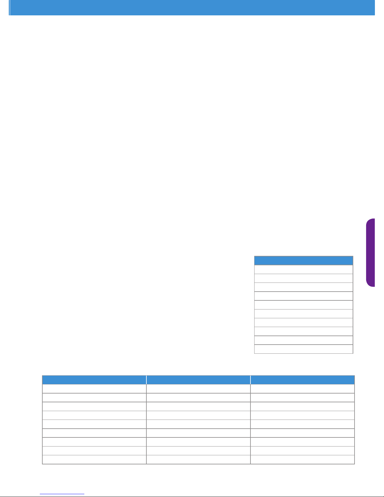
ZX Platform Condensing Unit
Product Manual
Page 2
About Emerson Climate Technologies
Emerson Climate Technologies, a business segment of Emerson, is the world’s leading provider of heating, air
conditioning and refrigeration solutions for residential, industrial and commercial applications. The group combines
best-in-class technology with proven engineering, design, distribution, educational and monitoring services to provide
customized, integrated climate-control solutions for customers worldwide. Emerson Climate Technologies’ innovative
solutions, which include industry-leading brands such as Copeland Scroll and White-Rodgers, improve human comfort,
safeguard food and protect the environment. For more information, visit EmersonClimate.com.
Emerson’s nancial performance is embellished with a record of unmissed annual dividend for 55 consecutive years.
For FY11, Emerson was ranked No. 120 on Fortune 500, a list of America’s largest companies, and placed No. 1 in the
same list’s Electronics and Equipment category.
The company invested approximately $696 million in engineering, development and customer solutions development
producing 773 patents worlwide from FY04 to FY10.
In 2010, 37% of the company’s global sales from new products are due to the application of innovative technologies.
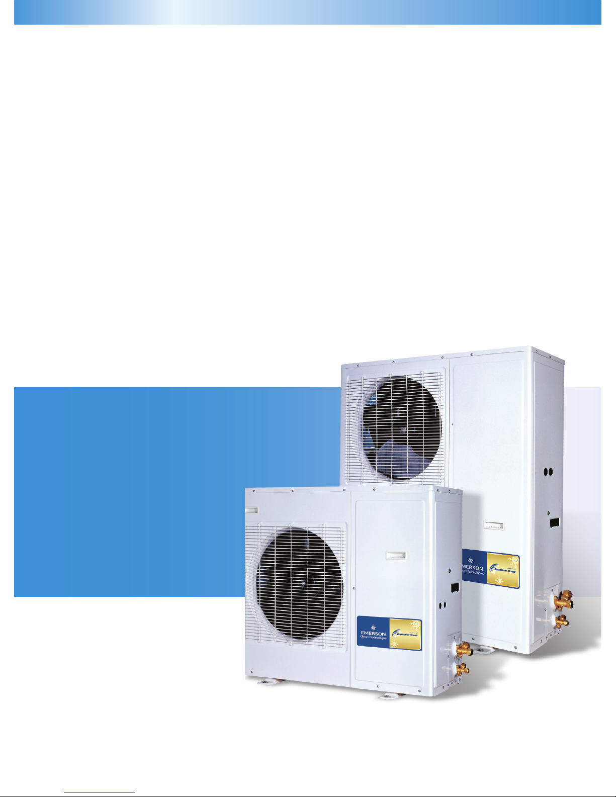
Emerson Climate Technologies is pleased
to offer the ZX platform refrigeration
condensing units (CDU) specically
designed for medium temperature (ZX-
MT), digital modulated variable capacity
medium temperature (ZXD) and low
temperature (ZXL-LT) refrigeration.
ZX series CDU has been highly successful
in the Asian market and enjoys proven
success with its energy savings and
customer-friendly electronic features.
Page 3

Index
Features and Value
ZX Design Platform .......................................................................................................................................................................................... 1
ZX Reliability Platform ...................................................................................................................................................................................... 1
ZX Performance Platform ................................................................................................................................................................................ 1
Standard Unit Features ..................................................................................................................................................................................... 2
ZX Platform Scroll Superiority .......................................................................................................................................................................... 3
Nomenclature .............................................................................................................................................................................................................. 4
Bill of Material (BOM) ................................................................................................................................................................................................... 4
Envelope
ZX Family: Medium Temperature ..................................................................................................................................................................... 5
ZXD Family: Digital Medium Temperature ...................................................................................................................................................... 5
ZXL Family: Low Temperature .......................................................................................................................................................................... 5
Physical Layout ............................................................................................................................................................................................................... 6
Application Guideline
Condensing Unit Handling............................................................................................................................................................................. 7
Installation .......................................................................................................................................................................................................... 8
Electrical Connection ....................................................................................................................................................................................... 9
Refrigeration Connections ............................................................................................................................................................................... 9
Vapor Injection Application Tip......................................................................................................................................................................... 9
Start Up And Operation .................................................................................................................................................................................... 10
Electronic Controller Assembly on a ZX Platform CDU
ZX/ZXL Controller Assembly …………………………………………………………………………………………………………………................................ 12
E2 Control Board ………………….………………………………………………………………………………........................................................ 14
E2 Control Board Dip Switch Setting ………………….……………………………………………………………………………............................ 15
Defrost Module Function Set .............................................................................................................................................................. 15
Diagnostic Initialization Message (ZX-MT and ZXL-LT ) ...................................................................................................................... 16
Diagnostic Messaging - LED Denition (ZX-MT and ZXL-LT ) .............................................................................................................. 16
E2 Controller Trip Set Points and Actions (ZX-MT and ZXL-LT Units) ………………………………………………….................................... 16
ZXD Controller Assembly ………………………..……………………………………………………………………………………………................................ 18
ZXD Electronic Controller ………………….………………………………………………………………………………………………………………… 19
Alarm Messaging - Digital Scroll Controller (ZXD) ........................................................................................……………………………. 23
Capacity and Power (kW)
ZX Family: Medium Temperature - R22
50 Hz ...........................................................................................................................................................……………………………...... 24
60 Hz ...............................................................................................................................................................…………………………….. 25
ZX Family: Medium Temperature - R404A/R507
50 Hz ...........................................................................................................................................................……………………………...... 26
60 Hz ...............................................................................................................................................................…………………………….. 27
ZXD Family: Digital Medium Temperature - R22
50 Hz ...................................................................................................................................................……………………………............. 28
ZXD Family: Digital Medium Temperature - R404A/R507
50 Hz ....................................................................................................................................................……………………………............ 29
60 Hz ...........................................................................................................................................................…………………………….... 29
ZXL Family: Low Temperature - R22
50 Hz ...........................................................................................................................................................…………………………….... 30
60 Hz .....................................................................................................................................................................……………………… 31
ZXL Family: Low Temperature - R404A/R507
50 Hz ...........................................................................................................................................................…………………………….... 32
60 Hz .................................................................................................................................................................………………………… 33
Technical Data
ZX Family: Medium Temperature at 50 Hz - PFJ ...............................................................................................…………………………………...... 34
ZX Family: Medium Temperature at 50 Hz - TFD ...................................................................……………………………....................................... 35
ZX Family: Medium Temperature at 60 Hz - TF5/TF7 ..................................................................……………………………………………………… 36
ZXD Family: Digital Medium Temperature at 50 Hz - TFD .............................................................................................................................. 37
ZXD Family: Digital Medium Temperature at 60 Hz - TF7 ............................................................................................................................... 38
ZXL Family: Low Temperature at 50Hz - TFD ................................................................................................................................................... 39
ZXL Family: Low Temperature at 60Hz - TF5/TF7 ............................................................................................................................................. 40
Wiring Diagram ........................................................................................................................................................................................................... 41
Packing Information .................................................................................................................................................................................................... 46
Conversion Chart ............................................................................................................................................................................................................ 46
Pressure Temperature Chart at Sea Level ......................................................................................................................................................................... 47
Contact Lists .................................................................................................................................................................................................................... 49
Page 4
1
ZX – Reliability Platform
Emerson Climate Technologies has designed the ZX platform
CDUs with extended operational capability in tough climatic
conditions. With our vast experience in the refrigeration industry,
ZX platform CDU is designed with a good protection scheme. ZX
protection scheme detect conditions that could cause damage
to the compressor, initiates a warning, temporary shutdown and
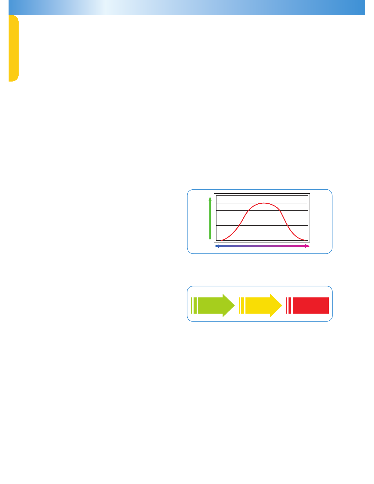
auto restarts. The control system will allow a complete shutdown
requiring manual restart only after several iterations of repeated warnings and temporary shutdowns are carried out. The control system
is driven by the built-in “E2 Controller”. Figure 02 shows the control strategy of the E2 Controller in a schematic form.
ZX – Performance Platform
Emerson Climate technologies with its leadership in scroll compression technology, apply the most advanced techniques to maximize
the possible operational efciency at specic application envelopes. ZX MT CDU applies a patented suction-line injection technology.
Scroll compressor inherently operates at higher efciency at MT application conditions. The suction-line injection provides a more
reliable MT operating envelope.
ZX MT CDU applies ZX series scroll compressor with liquid injection into the suction-line using an electronic expansion valve (EXV).
The EXV maintains an optimum feed of partially vaporized liquid refrigerant in the compressor suction to maintain a safe discharge gas
temperature. The controlled discharge gas temperature provides a more reliable solution for the MT envelope.
ZXL LT CDU applies vapor injection technology to achieve higher efciency in LT refrigeration. Vapor injection allows an economizer
cycle to be applied on a scroll compressor thereby greatly enhancing compressor efciency. This technology can be likened to 2- stage
compression with economizer cycle. Vapor injection improves efciency by as much as 12% over a liquid injection system of the same
type. ZXL LT CDU applies ZXI series vapor injected compressor with vapor injection plate heat exchanger (PHE) to implement the vapor
injection technology.
ZX – Design Platform
The ZX platform CDUs are designed to provide the best operational
cost savings on a year around basis. Refrigeration equipment
operate continuously for7 days, 24 hours and 365 days. The ZX and
ZXI compressors, injection scheme and heat exchanger designs
are optimized to provide best efciencies at annual averaged
temperature rather than at typical rating conditions. The typical
ambient on an annual basis follows a normal distribution pattern.
The highest and lowest ambient happens only for few hours as
shown in gure 01.
Hours
Low Ambient High Ambient
Figure 01. Shows Annual Typical Ambient Pattern
Real Time Monitoring
Of CDU Conditions
Warning Mode
Temporary Shutdown,
Signal, Auto Restart
Lock Out Mode
Alarm, Dialer Relay
Activation, Manual Restart
Figure 02. Control Strategy of the E2 Controller
ZX Platform Condensing Unit was designed based on three factors
demanded by industry users:
Energy Efficiency - Utilizing Copeland Scroll
®
compressor technology, variable speed fan motor, large capacity condenser coil
and advanced control algorithms, energy consumption is signicantly reduced. End-users can save more than 20% on annual energy
costs rather than using hermetic reciprocating units.
Reliability - Combining the proven reliability of Copeland Scroll
®
compressors with advanced electronics controller and
diagnostics, equipment reliability is greatly enhanced. Fault code alerts and fault code retrieval capabilities provide information to
help improve speed and accuracy of system diagnostics. Integrated electronics provide protection against over-current, over-heating,
incorrect phase rotation, compressor cycling, high pressure resets, low pressure cut-outs. It can also send out a warning message to
an operator when there is a liquid oodback, which can prevent critical damage on the unit.
Flexibility - The slim shape and light weight make the ZX Condensing Unit aesthetically appealing and easy to install. The ultra
quiet variable-speed fan motor signicantly reduces exterior sound levels, allowing additional location exibility. Combined with wall
mounting capability, the ZX Condensing Unit delivers unmatched exibility.
ZX Condensing Units are greatly suitable for walk-in cooler and freezer applications.
The advance scroll compressor technology, fan speed control and electronic controller are precisely collaborated in all units.
It also introduces variable-speed fan motors that go beyond national standards. Guaranteed dependable performance and
operation in food service applications while conveying higher energy efciency and lower sound levels are the main objectives.
Page 5
ZX Platform Condensing Unit
2
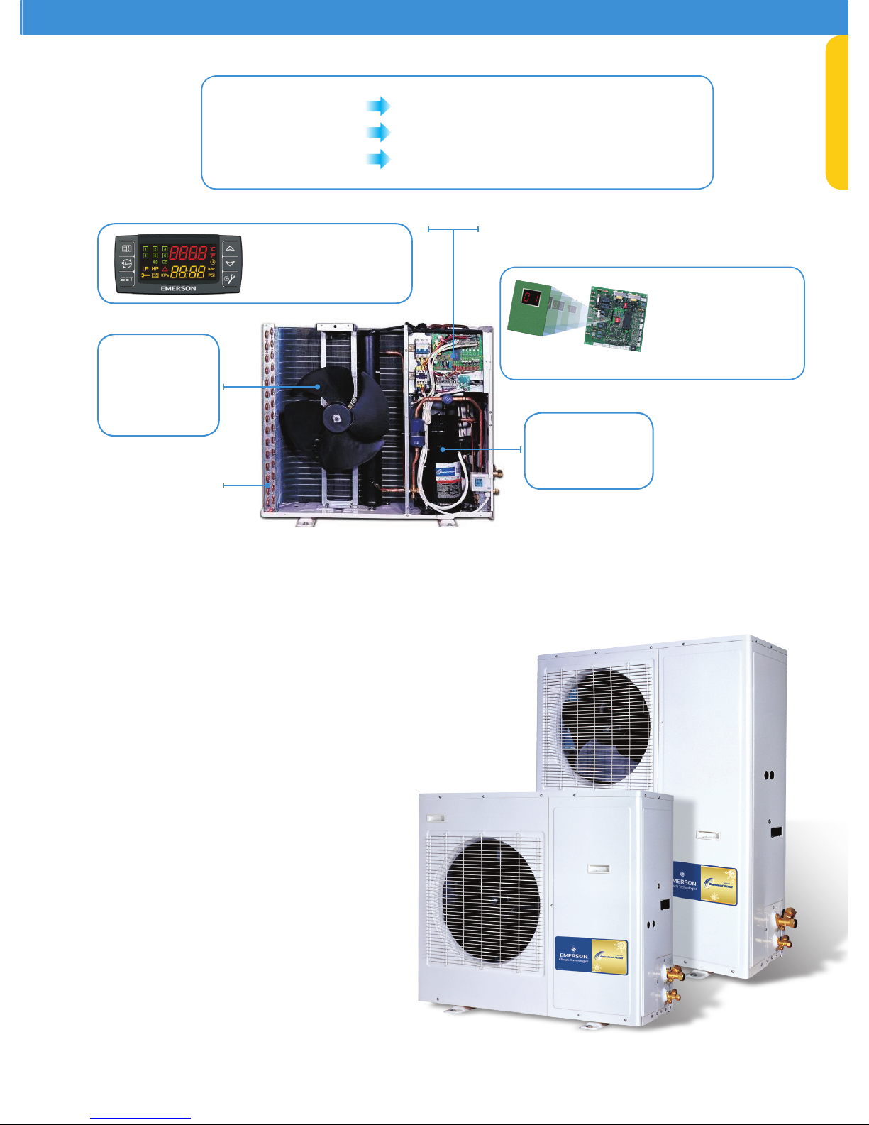
Figure 03. ZX Platform CDU Features
Standard Unit Features
• Pre-painted enclosures for corrosion protection.
• Heavy duty steel base with 23 mm raised legs.
• Brass service valves located externally for
easy access.
• Raised electrical access panel for easier
serviceability.
• Receivers with fusible plug, liquid shut-off valve
and charging port.
• Easy to read moisture indicator.
• Variable-speed PSC fan motors.
• Advanced performance alert diagnostics.
• Over-sized condenser coils with additional n
corrosion protection for coastal zones.
• Light weight, slim-line prole for maneuverability
and ease of installation.
• All units are factory tested for braze joint leaks,
wiring connections, electrical continuity and startup performance.
• Oil separator and accumulator standard on low
temperature models.
• Operating ambient is 48°C to -23°C*.
Proprietary Electronic Algorithms to Control Fan
Speed, Optimizing Energy Performance for Local
Seasonal Ambient Temperatures
Copeland Scroll
Compressor Technology
• High Efciency
• Ultra Quiet
• High Reliability
Variable Speed PSC
Fan Motors
• High Efciency
• Ultra Quiet
• Optimizes Air-
Flow
for Maximum
Heat Transfer
Oversized Condenser Coil
for Maximum Heat
Transfer
• Compressor Reverse Rotation
• Compressor Over Current
• Compressor Internal Motor Protector Trip
• Discharge Gas Over Heat
• High Pressure Cut Out
• Low Pressure Cut Out (only on MT series)
• Refrigerant Flood Back
• Compressor Minimum Off Time
• Internal Thermal Sensor Failure
Diagnostic
Digital
Messaging
Built-in ZX Platform
Controller
- Shuts down unit during failure
- With real time monitoring of
compressor operating conditions
ZXD Series
ZX and ZXL Series
Diagnostic Protection Increased Reliability and Lower Maintenance Costs
Flexibility More Installation Options
Highest Efciency
Lower Energy Bills
Page 6
3
ZX Platform – Scroll Superiority
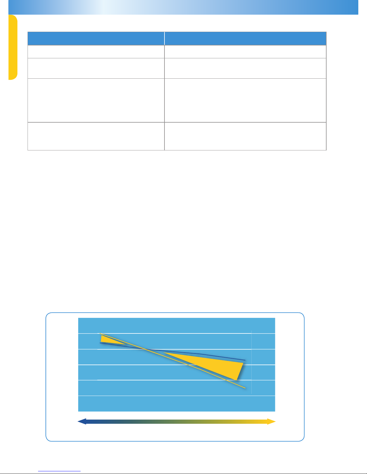
Scroll compressors deliver atter capacity compared to reciprocating compressor condensing units due to the high volumetric efciency
of scroll compressors. Flatter capacity can otherwise be described as lower change in capacity with change in outdoor ambient. This is
schematically shown in Figure 03. Flatter capacity brings certain inherent advantages, which highly benet users and stored products.
Some of the benets of atter capacity on ZX platform CDUs are described below.
1. Smaller unit selection: Condensing units are selected to match the required refrigeration capacity at the highest required
ambient. Flatter capacity allows a smaller unit selection compared to reciprocating compressor CDU.
2.
Lower operating cost: At lower ambient conditions, ZX platform CDU delivers capacity closer to the cooling load. In
contrast, reciprocating compressor CDU delivers capacity in far excess of what is required. This helps the ZX platform CDU to
operate at relatively higher evaporating temperature. Higher evaporating temperatures improve compressor efciency. In
addition, higher evaporating temperature reduces the rate of ice formation on the evaporator coils/frost build-up. Lower frost
build-up improves the evaporator heat exchange efciency. It also reduces the defrost heat demand, thereby resulting in lower energy
needed for defrost.
3.
Freshness of food: Another benet of higher evaporating temperature is reduced dehumidication by the evaporator coil.
This allows higher relative humidity in cold room or cold cases. Higher relative humidity reduces weight shrinkage and improves
freshness of stored product.
Low Ambient High Ambient
Higher
Evaporating Temp
ZX Capacity
Reciprocating Capacity
Allows
Smaller Unit
Figure 04
Features Owner/Enterprise Benefit
Energy improvement (More than $350 per year) •Lower operating costs
Sound improvement
• Creating a more comfortable environment for guests
• Beneficial for regions with noise ordinances
Diagnostic protection capabilities
• Reduces cost of nuisance calls
• Extends life of your equipment
• Reduces potential service costs
• Maintains your equipment to original standards, maintaining
energy efficiency and temperature control
• Have confidence in what your contractor is fixing
Slim profile, lighter weight, and optional wall mount capability
• Lower installation costs
• Improved appearance of your enterprise site
• Avoids more costly solutions for potential location issues
*For applications outside these guidelines, please contact Application Engineering.
Page 7
ZX Platform Condensing Unit
4
Nomenclature
Z X L 0 2 0 E - T F D - 4 5 1
Unit Family
= Medium Temp
L = Low Temp
D = Digital Medium Temp
2.0 to 7.6 HP
E = Ester oil
O = Mineral Oil
PFJ = 220V/240V- 1ph- 50 Hz
TFD = 380V/420V- 3ph- 50 Hz
TF5 = 200V/230V- 3ph- 60 Hz
TF7=380 - 3ph - 60 Hz
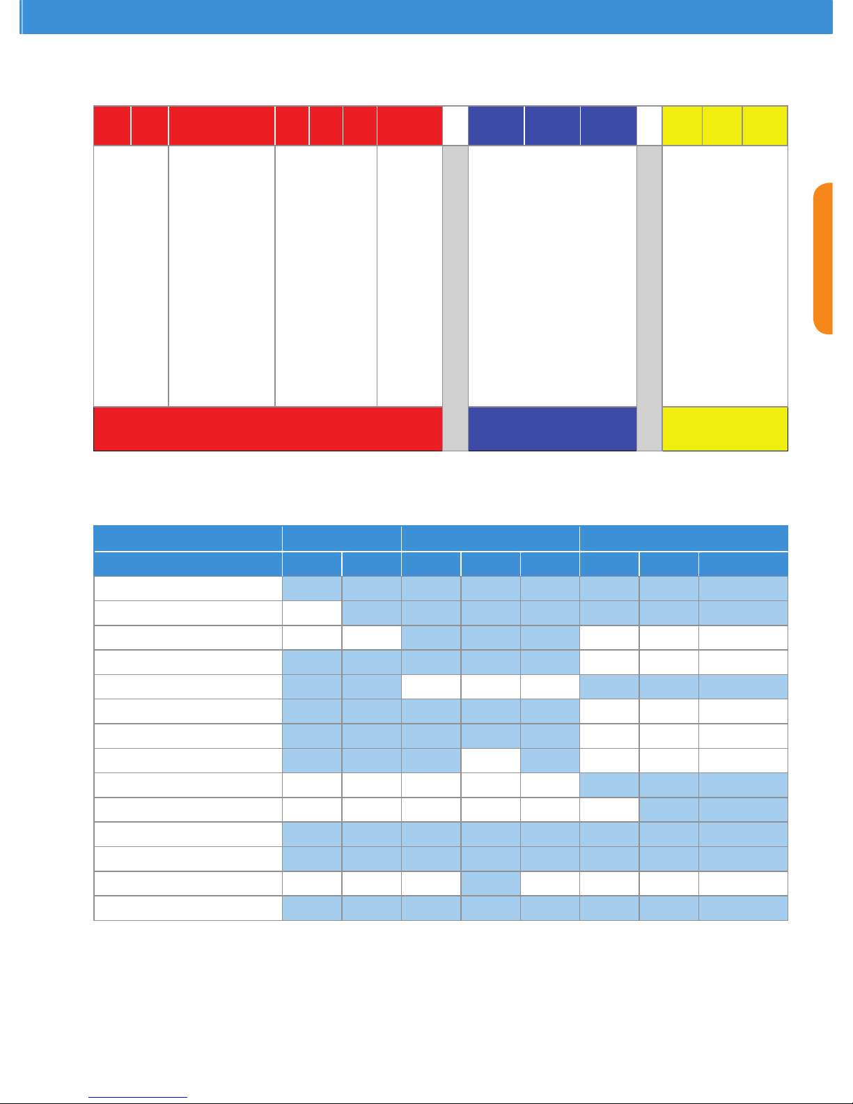
Bill of Material
Base Model Electrical Code Bill of Material
BOM
CDU Family ZX ZXL ZXD
BOM 401 451 451 461 471 450 451 461
Liquid Line Filter Dryer/Sight Glass
Oil Separator
Accumulator
Adjustable LP Switch
Fixed LP Switch
E2 Controller
Diagnostic Module
Buzzer
Digital Scroll Controller
Fan Speed Controller
Circuit Breaker
Sound Jacket
Defrost Module ACC ACC ACC ACC
Filter Drier V
Notes: E2 controller has fan speed control function
“V” indicates are type connection
“ACC” indicates accessory
Page 8
5
Envelope
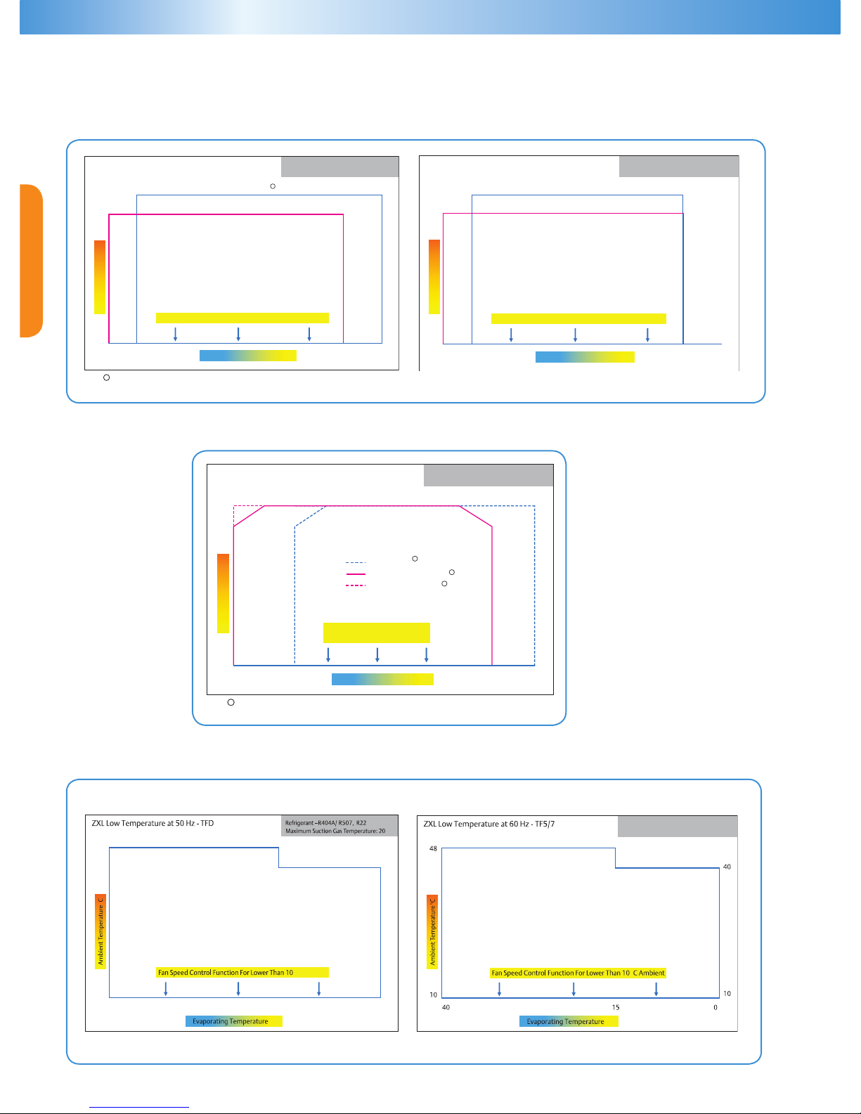
ZX Family : Medium Temperature
Refrigerant –R404A/ R507, R22
Maximum Suction Gas Temperature: 20
0
C
R404A/ R507
R22 Except ZX0750
Ambient Temperature
0
C
10
48
43
-20-15 125
10
Evaporating Temperature0C
Fan Speed Control Function For Ambient Lower Than 100C
ZX Medium Temperature at 50 Hz - PFJ / TFD
1
1
Note : For model ZX0750 Max Amb: 43°C , Max Evap: 5°C
Fan Speed Control Option
For Ambient Lower Than 10
0
C
Refrigerant –R404A/ R507, R22
Maximum Suction Gas Temperature: 20
0
C
Ambient Temperature
0
C
10
48
43
2101-51-02- 50
10
Evaporating Temperature0C
ZXD Digital Medium Temperature at 50 Hz - TFD
at 60 Hz - TF7
1
Note : For model ZXD075/E Max Amb: 43°C , Max Evap: 5°C
R404A/ R507 18°C RGT
R404A/ R507 10K SH
R22 10K SH
1
1
1
ZXD Family : Digital Medium Temperature
Refrigerant –R404A/ R507, R22
Maximum Suction Gas Temperature: 20
0
C
R404A/ R507
R22 Except ZX0750
Ambient Temperature
0
C
10
48
43
-20-15 125
10
Evaporating Temperature0C
Fan Speed Control Function For Ambient Lower Than 10
0
C
ZX Medium Temperature at 50 Hz - PFJ / TFD
1
1
Note : For model ZX0750 Max Amb: 43°C , Max Evap: 5°C
Refrigerant –R404A/ R507, R22
Maximum Suction Gas Temperature: 20
0
C
R404A/ R507
R22
Ambient Temperature
0
C
10
50
43
551-02-
Evaporating Temperature0C
Fan Speed Control Function For Ambient Lower Than 100C
ZX Medium Temperature at 60 Hz - TF5/7
ZXL Family : Low Temperature
0
C
0
10
48
051-04-
10
43
0
C
0
C Ambient
0
C
0
10
48
051-04-
10
43
0
C
0
C Ambient
Refrigerant –R404A/ R507, R22
Maximum Suction Gas Temperature: 20
0
C
--
0
C
0
Page 9
ZX Platform Condensing Unit
6
Physical Layout of the ZX Platform CDU
The unique features of ZX platform CDU as described above are quite different from the conventional CDUs available in the market.
Apart from this, ZX platform CDU also comes with a package of other conventional features which are part of a well designed
condensing unit.
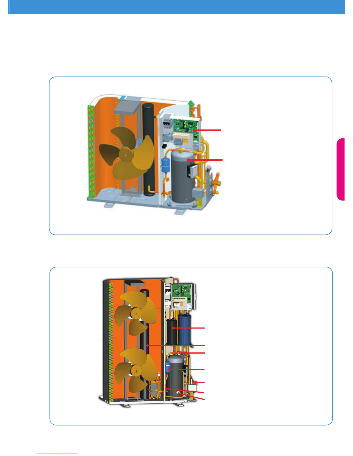
ZX- MT, ZXL-LT E2 Controller
ZXD Digital Scroll Controller
Scroll Compressor
Figure 05: Identies the electronic controller assembly on a ZX Platform CDU
Figure 06: Identies other major components layout on a ZX Platform CDU
Oil Separator
(Optional In MT CDU)
Liquid Receiver
Liquid Sight Glass/
Moisture Indicator
Liquid Filter Drier
Suction And Liquid
Service Valve
Receiver Out Service Valve
Compressor Oil Sight Glass
Page 10
7
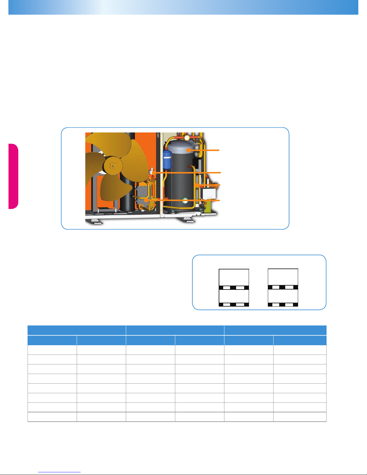
ZXI Vapor Injected
Scroll Compressor
Vapor Injection control EXV
Vapor Injection Tube
To Compressor
Vapor/ Liquid Sub Cooling PHE
Condensing Unit Handling
Transport and Storage
Move ZX/ZXD/ZXL unit only with appropriate mechanical or
handling equipment according to weight. Keep in the upright
position. Do not stack single boxes on top of each other without
pallet in any case.
Keep the packaging dry at all times.
Application Guideline
In ZX MT units, suction line injection is applied to the compressor suction. Suction line injection allows a reliable and efcient MT
envelope of up to -15°C (R22) and -20°C (R404A) evaporating temperature. In suction line injection, a part of liquid refrigerant is
added into the compressor suction gas. Suction injection de-superheats the suction gas and controls the compressor discharge
temperature. This is implemented through electronic control by the E2 controller and an electronic expansion valve (EXV). The E2
monitors the compressor discharge temperature and optimizes the opening of the EXV for optimal discharge gas control.
In ZXL LT units, vapor injection is applied to the compressor. Vapor injection enhances the compressor efciency by applying 2-stage
compression with an economizer refrigeration cycle. Vapor injection eliminates the need for liquid injection, which would otherwise
have been required to operate a reliable LT envelope down to -40°C evaporating temperature. In vapor injection, a part of liquid
refrigerant is expanded and passed through a heat exchanger. In the heat exchanger, this expanded refrigerant absorbs heat from the
main liquid line and sub-cool the main liquid. The expanded refrigerant vaporizes while passing through the heat exchanger and is
supplied back into the scroll intermediate pockets through the vapor-injection tube. The sub-cooling of the main liquid increases the
compressor capacity by as much as 30%. The gure 14 below identies the key components of the vapor injection assembly.
Figure 07: Key Components Of The Vapor Injection Assembly
22
11
max
300 Kg
Storage
Transport
max
300 Kg
max
300 Kg
Net Weight
ZX ZXD ZXL
Model Weight (kg) Model Weight (kg) Model Weight (kg)
ZX0200/E 76 ZXD0400/E
2
104 ZXL0200/E 79
ZX0250/E 79 ZXD0500/E
3
112 ZXL0250/E 81
ZX0300/E 79 ZXD0600/E
4
114 ZXL0300/E 81
ZX0400/E
1
91 ZXD0750/E
5
122 ZXL0350/E 93
ZX0500/E 108 ZXL0400/E 93
ZX0600/E 112 ZXL0500/E 106
ZX0750/E 118 ZXL0600/E 116
ZX0760/E 121 ZXL0750/E 121
Notes: 1 100 kg for models under 60 Hz TF5/7 and 50 Hz PFJ
2
109 kg for models under 60 Hz TF7
3
117 kg for models under 60 Hz TF7
4
121 kg for models under 60 Hz TF7
5
127 kg for models under 60 Hz TF7
Page 11
ZX Platform Condensing Unit
8
Installation
Copeland ZX condensing units are delivered with a holding charge of neutral gas. The condensing unit should be located in such a place
to prevent any dirt, plastic bag, leaves or papers from covering the condenser and its ns. The unit must be installed without restricting
the airow. A clogged condenser will increase the condensing temperature, thus reduce the cooling capacity, and lead to a high-
pressure switch tripping. Clean the condenser ns on a regular basis.
Installation / Piping Instructions
It is recommended that a clearance of 8 inches from the wall (or the next unit) be maintained from the unit’s left and rear panel whereas
a clearance of 20 inches is to be maintained from the unit’s right, top and front panels. Both service access and air ow have been
considered in making these recommendations. Where multiple units are to be installed in the same location, careful consideration for
proper clearance needs to be given to each individual unit.
Ideally, the unit should be mounted level on a solid concrete slab with rubber strips between unit feet and concrete. However, these units
have been designed for mounting on suitable brackets for wall mounting. In this case it is equally important that the spatial guidelines
given above are followed, and additional consideration needs to be given for possible air recycling if units are stacked above and below
each other. In general terms, air by-pass around each condenser and between each unit should be avoided at all times.
Pipe sizing should not only be of sufcient size to ensure optimum performance and good oil return, but it also needs to take into
account the full capacity range through which this particular unit will need to operate. Follow the ASHRAE guidelines for proper
piping practices.
Location and Fixing
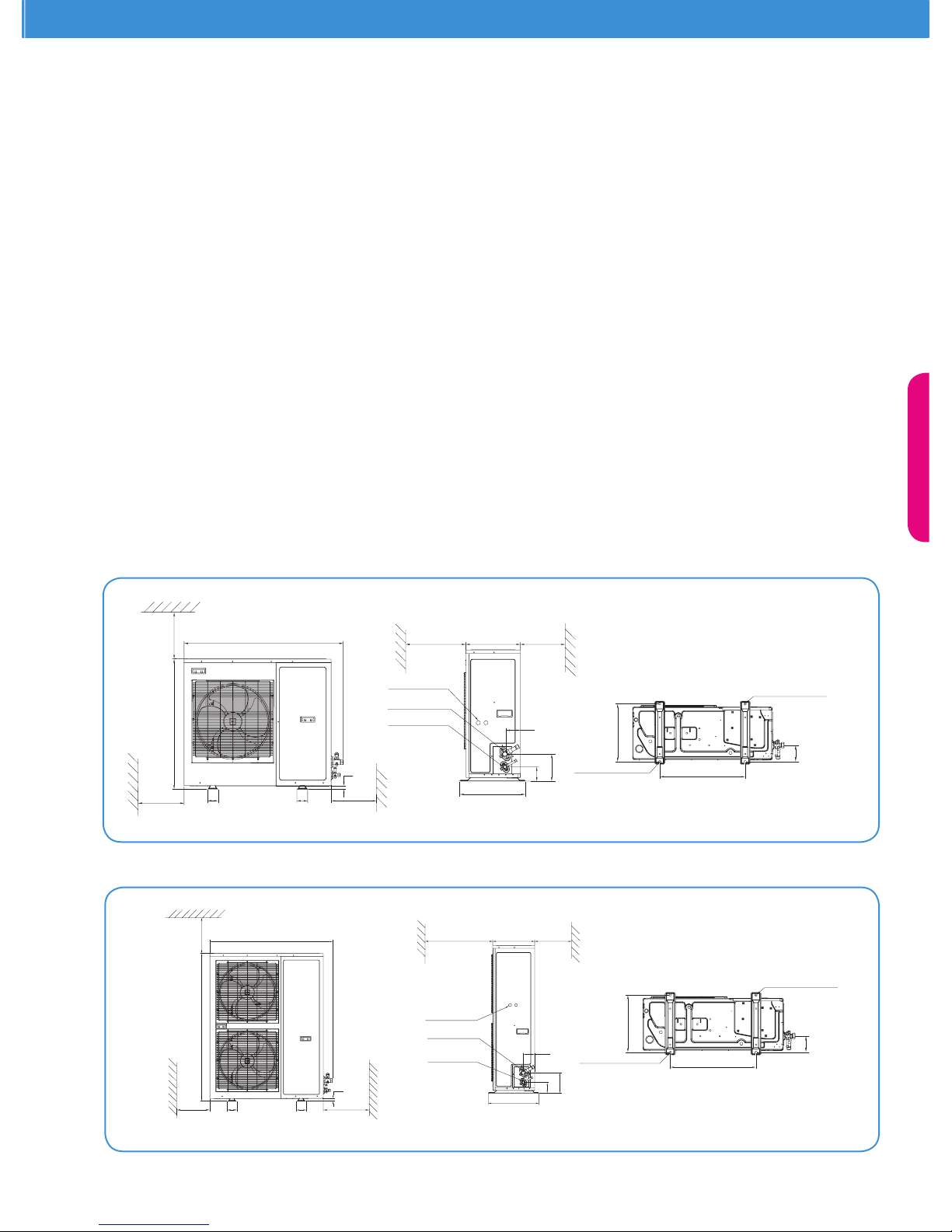
The unit should always be installed in a location that ensures clean air ow. It is recommended that a clearance of 300 mm from the wall
(or the next unit) be maintained from the unit’s left and rear panels whereas a clearance of 500 mm must be maintained from the unit’s
right, top and front panels (seen facing the front of the unit). Both service access and airow have been considered in making these
recommendations. Where multiple units are to be installed in the same location, the contractor needs to consider each individual case
carefully. There can be many variations of unit quantities and available space and it is not the intention of this manual to go over these.
Ideally, the unit should be mounted on a solid concrete slab with anti-vibration pads between unit feet and concrete. However the ZX
condensing unit has also been designed for wall mounting on suitable brackets. Wall mounting brackets are not included. Another factor
to consider in nding a good installation site is the direction of the prevailing wind. For example, if the air leaving the condenser faces
the prevailing wind, the air ow through the condenser can be impeded, causing high condensing temperatures ultimately resulting in
reducing unit life. A bafe is a remedy for this situation.
Dual Fan Unit
4 to 7.6 HP
388
110
580
2-R7.5MM GROOVE
70
70
1242
500300
500
1029
23
172
90
300500
Liquid
Service Valve
Suction
Service Valve
Power
Supply Hole
424
94
352
2 Holes 15mm DIA
Single Fan Unit
2 to 4 HP
840
500
500
300
7070
23
1029
300500
Power
Supply Hole
Suction
Service Valve
Liquid
Service Valve
90
172
424
352
94
388
110
580
2-R7.5MM GROOVE
2 Holes 15mm DIA
Fixing dimensions and distances - Single fan unit
Fixing dimensions and distances - Dual fan unit
Page 12
9
Electrical Connection
Power Supply
The ZX condensing unit electrical connection to the power
supply must be made by qualied technicians, who should
refer to the electrical diagrams located inside the electric
connection panel. The units are designed for below power
supply at ± 10% voltage tolerance. The circuit breaker must
be switched off before opening the front panel.
Electrical Wiring
Before commissioning, ensure that the neutral “N” wire is
connected to the terminal block (“N” furthest to the right). After proper connection of the ZX condensing unit, the control LED on
the power board and control board will light. For more details, see wiring diagram in Appendix.
Refrigeration Connections
Refrigeration Piping Installation
All interconnecting pipes should be of refrigeration grade, clean, dehydrated and must remain capped at both ends until installation.
Even during installation, if the system is left for any reasonable period of time (say two hours), pipes should be re-capped to prevent
moisture and contaminants from entering the system.
Do not assume that the service connection sizes on the unit (at the service valves) are the correct size to run your interconnecting
refrigeration pipes. The service valve sizes have been selected for convenience of installation and in some cases (larger units) these
may be considered too small. However for the very short pipe run within our units, these service connection sizes are adequate. All
interconnecting pipes should be sized to satisfy the duty required.
Usually the suction line is insulated, but the liquid line is not. However the liquid line can pick up additional heat from the ambient
and adversely affect the sub-cooling desirable for the liquid refrigerant before it enters the expansion valve.
The pipe should be sized to ensure optimum performance and good oil return. The sizing must also take into account the full capacity
range through which this particular unit will need to operate.
Pipe runs should be kept as short as possible, using the minimum number
of directional changes. Use large radius bends and avoid trapping of oil and
refrigerant. This is particularly important for the suction line. The suction
line should ideally slope gently towards the unit. Recommendation slope is
1/200~1/250. P traps, double risers and reduced pipe diameters may be required
for suction lines where long vertical risers cannot be avoided. All pipes should
be adequately supported to prevent sagging which can create oil traps. The
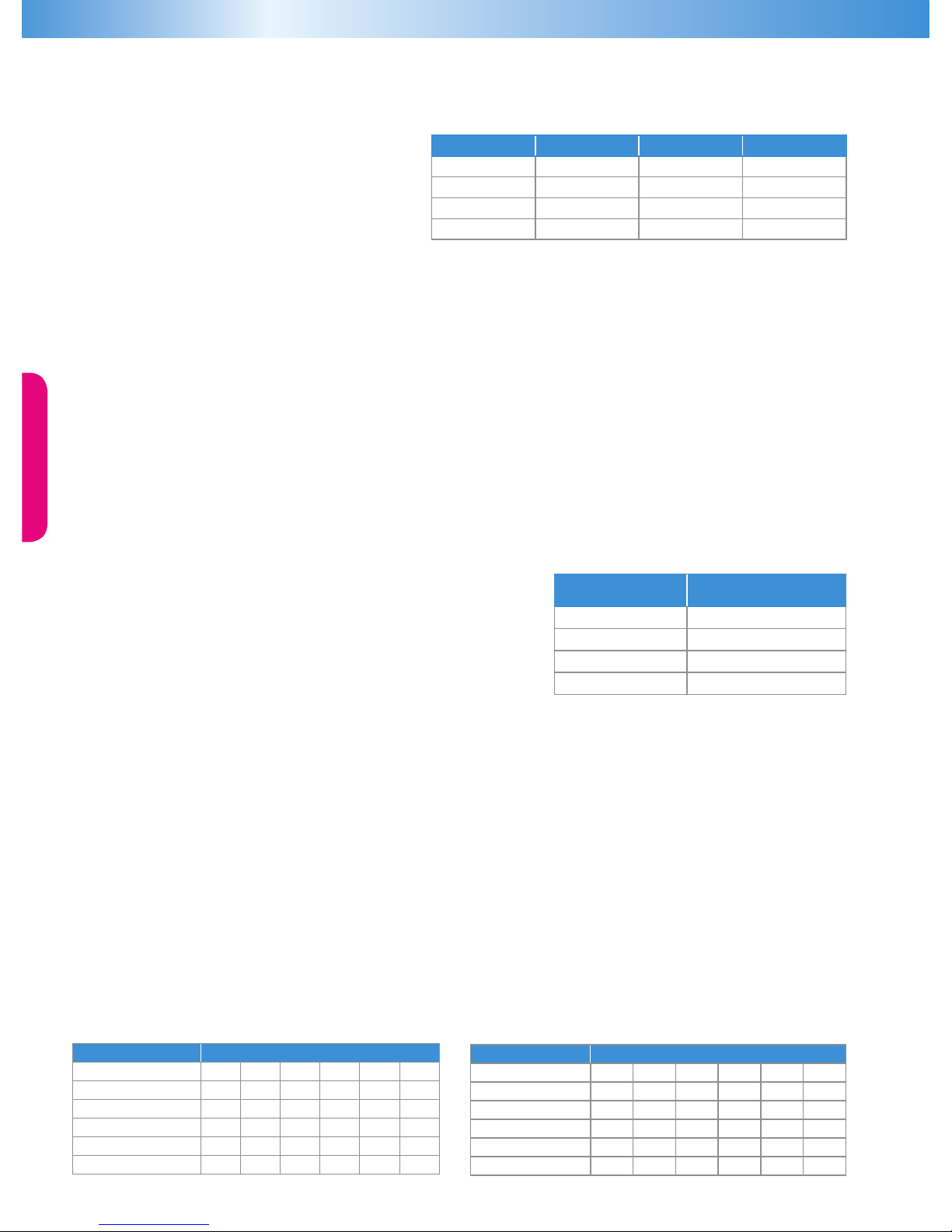
recommended pipe clamp support distance is shown in the table.
ZXL Liquid Line Insulation
ZXL liquid line should be insulated with a 19 mm insulation thickness. Temperature could be as low as –15°C.
Codes HZ
Phase
Voltages
PFJ 50
1
220/240
TFD 50
3
380/420
TF7 60
3
380
TF5 60
3
200/230
Tube Size
Max distance between
2 clamp support
12.7mm (1/2 inch) 1.20 m
16.0mm (5/8 inch) 1.50 m
22.0mm (7/8 inch) 1.85 m
28.5mm (1 1/8 inch) 2.20 m
Typical Liquid Line Temperature oC
R22 Ambient °C
Evap Temp oC 20 27 32 38 43 48
-40 -11 -3 7 7 11 14
-35 -8 -1 9 9 13 16
-30 -4 2 12 12 16 19
-25 0 5 14 14 19 23
-20 5 9 18 18 22 26
R404A Ambient°C
Evap Temp °C 20 27 32 38 43 48
-40 -8 -1 3 8 13 19
-35 -4 2 6 11 15 21
-30 0 6 9 13 18 23
-25 5 10 13 17 21 26
-20 9 14 17 20 24 30
ZXL-LT Unit (Liquid Line Temperature)
Vapor Injection: Specic Application Tips
ZXL-LT CDU
ZXL-LT CDU applies vapor injection technology. As explained in the previous section, vapor injection improves LT operational
efciency and provides a reliable LT envelope. Vapor injection sub cools the main liquid line using the economizer cycle. The sub
cooling of liquid line calls for some specic application tips which are applicable only for ZXL-LT CDU. They are;
1. Liquid line pipe connecting the CDU service valve to the evaporator expansion valve has to be well insulated separately. The
recommended insulation thickness is 12.5 mm (1/2 inches)
2. The lower liquid in temperature can increase the evaporator expansion valve capacities. Please follow valve manufactures
recommended liquid temperature correction factors for proper selection of evaporator expansion valve.
Page 13
ZX Platform Condensing Unit
10
OUTSIDEINSIDE UNIT
End of tube
During brazing
protect housing with
damp cloth
During brazing
pull back fire
insulation
Start Up and Operation
Before commissioning, ensure that all valves on the condensing unit are fully opened.
Evacuation
The evacuation procedure is based upon achieving an actual system vacuum standard and is not time dependent. Before the
installation is put into commission, it has to be evacuated with a vacuum pump. Proper evacuation reduces residual moisture to
50ppm. The installation of adequately sized access valves at the furthest point from the compressor in the suction and liquid lines
is advisable. To achieve undisturbed operation, the compressor valves are closed and the system is evacuated down to 0.3 mbar /
0.225 Torr. Pressure must be measured using a vacuum pressure (Torr) gauge on the access valves and not on the vacuum pump; this
serves to avoid incorrect measurements resulting from the pressure gradient along the connecting lines to the pump.
Charging Procedure
Refrigerant Charging Procedure
The scroll compressor design requires system charging as quickly as possible with liquid refrigerant into the liquid line. This will
avoid running the compressor under conditions where there is insufcient suction gas. Sufcient suction gas is available to cool not
only the motor but also the scrolls. Temperature builds up very quickly in the scrolls if this is not done. Do not charge vapor (gas)
refrigerant into the ZX Scroll unit. The suction service valve must not be fully closed at any time while the compressor is running. To
do so would cause damage to the compressor in the same manner as explained above. This valve is provided for ease of connection
and for the tting of service gauges without removing the unit panel. It is recommended to charge the ZX unit with refrigerant via
its service valves. It is recommended to break the vacuum in the system with a partial charge of the refrigerant, before starting the
system. For charge adjustment, it is recommended to check the liquid sight glass just before the expansion valve.
Oil Charging Procedure
ZX CDUs are delivered with a full oil charge in both the compressor and the oil separator. The oil level should be visible in the compressor
sight glass. All systems will trap some oil and in some cases it may be necessary to add oil if pipes are long, if the vertical rise is high
and if the piping is not well designed. The oil level should be monitored carefully during commissioning, checked after 4 – 8 hours and
checked again after 24 hours of normal operation. The ideal oil level is between ¼ and ¾ sight glass level but if any oil is visible in the
sight glass the compressor can operate safely. If oil is not visible in the sight glass proceed as follows:
1. Perform a manual defrost on all evaporators simultaneously.
2. Operate the compressor (at 100% load for ZXD) for 5 minutes after defrost is complete. The unit will automatically tend to
operate (at 100% load for ZXD) after defrost as the evaporators recover their set-point temperatures.
3. Check that the oil level is at ¼ sight glass or higher but not over the top of the sight glass.
4. If oil is not visible add oil until the level reaches the ¾ sight glass level.
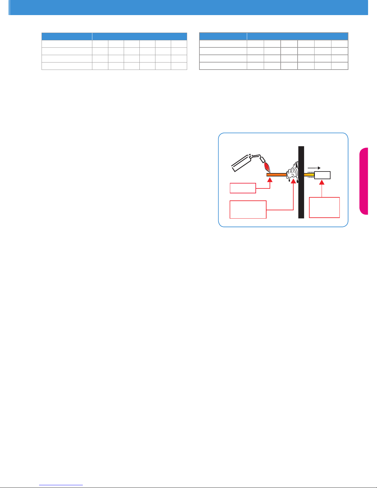
Brazing Recommendations
Maintain a ow of oxygen-free nitrogen through the system at a very low pressure during brazing. Nitrogen displaces the air and
prevents the formation of copper oxides in the system. If copper oxidization is allowed to form, the copper oxide material can later be
swept through the system and block screens such as those protecting capillary tubes, thermal expansion valves, and accumulator oil
return holes.
This minimizes any entry of contaminants and moisture.
• Remove the liquid line connection cap.
• Then remove the suction connection cap.
• Open both valves midway. Care should be taken to avoid the holding
charge from releasing too quickly.
• Be sure that tube tting inner diameter and tube outer diameter are
clean prior to assembly.
• Since both tubes are extended from the condensing unit housing,
we recommend insulating the housing by using a wet cloth on the
copper tubing.
• Recommended brazing materials: a copper / phosphorous or copper
/ phosphorous / silver alloy rod should be used for joining copper to
copper whereas to join dissimilar or ferric metals, use a silver alloy
rod, either ux coated or with a separate coating.
• Use a double tip torch.
Typical Values With Individual Values Within +/-5oC
Note: ZXL CDU is designed with vapor injection technology. The condenser liquid line temperature will be sub cooled by the vapor injection plate heat exchanger.
R22 Ambient °C
-15 10 13 21 21 25 30
-10 15 17 25 25 29
-5 20 22 29 29 33
0 26 26 33 33 37
R404A Ambient°C
-15 13 18 21 24 28 34
-10 16 22 25 29 33
-5 20 26 29 33 37
0 23 29 33 38 42
Page 14

11
Adding Oil
The simple and ideal way to add oil is to pump the oil into the suction side when the unit is running. Discharge pressure from the unit or
refrigerant pressure from a cylinder can be used to force oil into the suction side. The oil will go directly into the compressor and the level
increase will be immediate.
NEVER CLOSE THE UNIT SUCTION VALVE AND USE THE COMPRESSOR TO SUCK OIL FROM A CONTAINER THAT IS AT ATMOSPHERIC
PRESSURE. THIS COULD DESTROY THE SCROLL COMPRESSOR IN A MATTER OF SECONDS.
Tools required: Manifold gauge set and hoses, oil tank of ~ 1 litre volume with suitable connections, oil, refrigerant.
Qualified Refrigerants And Oil
REFRIGERANT OIL
R404A/507 Emkarate RL 32 3MAF Mobil EAL Artic 22 CC
R22 Suniso 3GS
Oils are pre-charged in both compressor and oil separator. Total oil volume (liter) for each unit is shown in the table below:
ZX ZXD ZXL
Model BOM Model BOM Model BOM
401 451 ALL ALL
ZX0200/E 1.18 1.68 ZXL0200/E 1.06
ZX0250/E 1.33 1.83 ZXL0250/E 1.06
ZX0300/E 1.33 1.83 ZXL0300/E 1.06
ZXL0350/E 1.74
ZX0400/E 1.83 2.33 ZXD0400/E 1.74 ZXL0400/E 1.74
ZX0500/E 1.83 2.33 ZXD0500/E 2.27 ZXL0500/E 1.74
ZX0600/E 1.66 2.16 ZXD0600/E 2.27 ZXL0600/E 2.27
ZX0750/E 1.66 2.16 ZXD0750/E 2.27 ZXL0750/E 2.27
ZX0760/E 1.66 2.16
Scroll Compressor Rotation Direction
Rotation Direction of Three Phase Scroll Compressors will only compress in one rotational direction. Direction
of rotation is not an issue with single phase compressors since they will always start and run in the proper direction. Three phase
compressors will rotate in either direction depending upon phasing of the power. Since there is a 50-50 chance of connecting power in
such a way as to cause rotation in the reverse direction, it is important to include notices and instructions in appropriate locations on
the equipment to ensure proper rotation direction when the system is installed and operated. Verication of proper rotation direction
is made by observing that suction pressure drops and discharge pressure rises when the compressor is energized. Reverse rotation of a
scroll compressor also results in substantially reduced current draw compared to specication sheet values. Suction temperature will be
high, discharge temperature will be low and the compressor may be abnormally noisy. There is no negative impact on durability caused
by operating three phase Copeland Scroll compressors in the reversed direction for a short period of time (under one hour). After several
minutes of operation in reverse, the compressor’s motor protection system will trip the compressor off. If allowed to repeatedly restart
and run in reverse without correcting the situation, the compressor will be permanently damaged. All three phase scroll compressors are
identically wired internally. As a result, once the correct phasing is determined for a specic system or installation, connecting properly
phased power leads to the same terminals will maintain proper rotation direction.
Brief Power Interruptions
Brief power interruptions (less than ½ second) may result in powered reverse rotation of single-phase refrigeration scroll compressors.
High-pressure discharge gas expands backward through the scrolls at power interruption causing the scroll to orbit in the reverse
direction. If power is reapplied while this reversal is occurring, the compressor may continue to run noisily in the reverse direction for
several minutes until the compressor internal protector trips. This has no negative effect on durability. When the protector resets, the
compressor will start and run normally.
Maximum Compressor Cycle
Maximum permitted starts per hour is 10.
Check Before Starting & During Operation
Both valves should be fully opened on the liquid line, in order to prevent trapping liquid.
• Check that all valves are fully opened.
• After starting and operation conditions are stabilized, it is recommended to check oil level in the compressor(s) and see if there
is a need to add oil to ensure a sufcient oil level (halfway up the sight glass).
Page 15
ZX Platform Condensing Unit
12
Fault Temporary Shutdown/Auto Restart Lock Out Errors/Manual Restarts
Phase Reversal/ Loss Of Phase Incorrect 3 Phase Sequence
High Pressure Trip < 5 Trips In 1 Hour 6th Trip Within 1 Hour
Low Pressure Trip (only on MT Units) At Every LP Trip No Lock Out
Discharge Gas Temperature Overheat < 5 Trips In 1 hour 6th Trip Within 1 Hour
Compressor Over Current < 5 Trips In 1 Hour 6th Trip Within 1 Hour
Compressor Short Cycling 3 Minutes Between Starts No Lock Out
Excessive Suction Flood Back ~ 20% Flood Back, Warning Only No Lock Out
Discharge Sensor Failure (only on LT Units) < 5 Trips In 1 Hour 6th Trip Within 1 Hour
Other Thermal Sensor Failures Warning Only No Lock Out
Table 02
E2 Fault Detection Items
* Compressor Phase Reversal
* Loss of Phase (In 3 Phase Models)
* Compressor Over Current
* Compressor Protector Trip Detection
* Discharge Gas Temperature Over Heat
* High Pressure Cut Out
* Low Pressure Cut Out (MT CDU Only)
* Excessive Refrigerant Flood Back
*Compressor Minimum Off Time
* E2 Sensor Failures
Table 01
Electronic Controller Assembly on a ZX Platform CDU
ZX/ZXL Controller Assembly
ZX platform E2 control offers multiple features which are unique to refrigeration condensing units. E2 real-time control monitors and
optimizes the suction or vapor injection performance to offer efcient performance in ZX MT and LT units. E2 also monitors compressor
operating parameters, so as to protect the system from unsafe operating parameters such as passing through a peak temperature hour
of a peak ambient day; or drop-out of a power-phase; or continued refrigerant loss in the system. E2 controller detects these situations
and, as a rst step, will initiate some corrective actions.
For example, when the LT unit experiences an extreme temperature day, E2 control decides to switch from vapor-injection-optimization
to discharge-gas temperature-control to allow the compressor to run safely and pass the extreme weather hours.
Another fault condition which is common in refrigeration systems is compressor overload. If the condenser coils are not cleaned
regularly, the compressor operating discharge pressures rises. This condition is gradual and in conventional CDUs, no advance warning is
provided to the user on this approaching undesirable situation. Ultimately, in such a situation, the internal protector in the compressor
trips. Two problems arise due to internal protector-trip. First: there is no alarm to detect the trip and second: a compressor internal
protector reset may take as long as an hour. This could be critical for the quality of frozen food in freezers or cases. On the other hand,
ZXL E2 controller detects the overload externally and actions a temporary shutdown. E2 Diagnostics will then start transmitting a fault
signal. After multiple attempts, and if the error repeats itself as high as six times within an hour, the E2 will nally shutdown the unit to
avoid expensive compressor failure.
The E2 will activate a buzzer to send an alarm signal at unit-lockout which then requires a manual restart. The buzzer is a standard part of
the ZX platform Gold version CDU . The buzzer can be remotely mounted and has volume and mute capability. The E2 is also designed
to activate an externally connected telephone dialer to send fault notice on a preset telephone number.
ZX platform units are designed to operate under extreme ambient temperatures of up to 48°C. This extremely high-ambient envelope,
combined with the intelligent E2 controller, provides unparalleled benets to customers.
The E2 control is also designed to apply a ZX defrost (DF) module. The ZX DF module is a basic time initiated DF module and is supplied as an optional accessory. The DF module has two rotary switches by which the user can set up the defrost duration and defrost
interval. The DF module also enables a manual defrost as an override to the rotary switch setting of defrost interval.
The E2 controller consists of two electronic board assemblies: E2 power board and
control board. The power board supplies constant DC power to the E2 control board.
The E2 control board carries the intelligent chip containing the canned programs. The
entire assembly is pre-installed and wired in the factory on a new unit. Both electronic
boards carry a LED light . If the LED lights are on after power-up of the unit, it indicates
normal and proper operation of the electronic boards. Once these lights are on, the
rest of the unit including the compressor is monitored and digital messages are shown
on the diagnostic panel.
Table 01 shows a list of fault detections enabled by E2 controller and diagnostics on ZX
platform CDU. The diagnostics are standard features on the Emerson ZX platform Gold
version.
Table 02 summarizes fault conditions under which the E2 controller initiates “temporaryshutdown—with-auto-restart” and “lock-out trip-condition with- manual-restart.”
Page 16
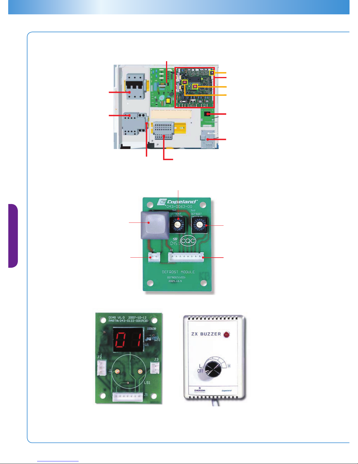
13
2-Bit Dip Switch
3-Bit Dip Switch
Rotary Switch
E2 Control Board
Power Isolation Switch
E2 Power Board
Compressor Contactor
Diagnostic Module
Fuse Holder Electrical Cable connectors
Defrost Module
(optional)
Defrost Duration (in Minutes)
Defrost Interval
(In Hours)
E2 Connector
Manual Defrost
Button
Remote Connector
For Manual Defrost
Remote Buzzer
With Volume
E2 Display Diagnostic
Remote Buzzer
With Volume
Page 17
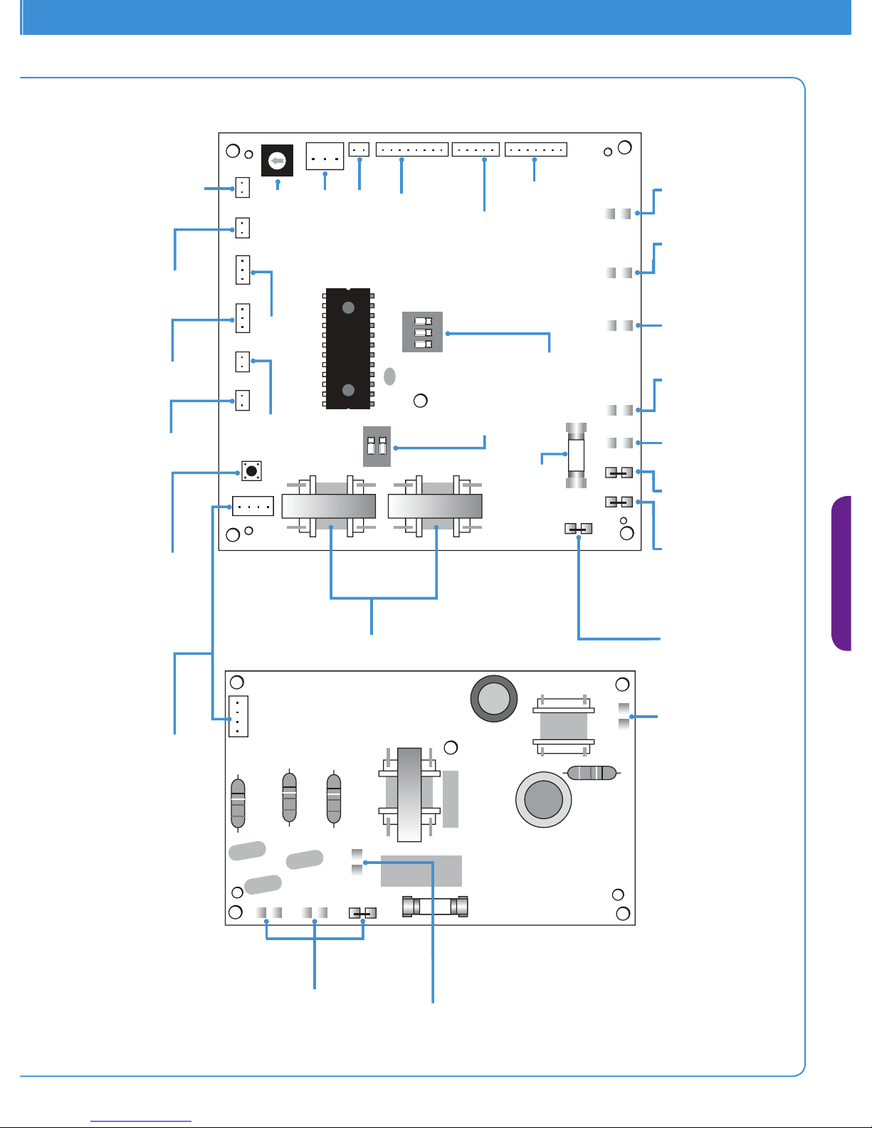
ZX Platform Condensing Unit
14
0
1
2
3
4
5
6
7
8
9
A
B
C
D
E
F
123
ON
12
ON
① ZXL Low Temperature Unit Only
② ZX Medium Tempeture Unit Only
③ Temperature Adjust Mode Only
J6:
Power Board-Main
Control Board
S1:
Main Control Board
Restart Button
Connector
RT1:
Condenser
Coil-In Temp.
Sensor
RT2:
Discharge
Temp. Sensor
RT3:
Ambient Temp.
SenSor
RT4:
Condensor
Mid-Coil Sensor
RT6:
PHE Vapor
Out Temp.
Sensor
RT6:
PHE Vapor Out
Temp.Sensor
S4:
Compressor Type
Setting Rotary-
Switch
J4:
High Pressure
Switch Connector
J3:
Low Pressure
Switch Connector
J5:
Defrost Module
Connector
Control Board
J1:
EXV Driver
Connector
J2:
Diagnosis Module
Connector
S2:
Evaporator Fan
Mode Setting
Dip-Switch
S3:
Compressor
Current Sensing
(Hi/Lo) Setting
Dip-Switch
JP13:
Compressor
Contactor Coil
JP12:
Liquid Line
Solenoid
Vlave Coil
JP11:
Condenser
Fan Motor
JP10:
Defrost
Heater
Contactor
or Relay
JP9:
Evap. Fan
Contactor
Coil
JP8:
Live Line
Input
JP7:
Null Line
Input
JP6:
Low Pressure
Control Switch
JP5:
Ground Line
JP4:
Null Line Input
JP1-JP3:
Three Phase
Power Supply Input
w
e
r B
oa
r
d
T1/T2:
Compressor
Current
Transformers
Fuse
Power Board and E2 Control Board Diagram
Page 18
15
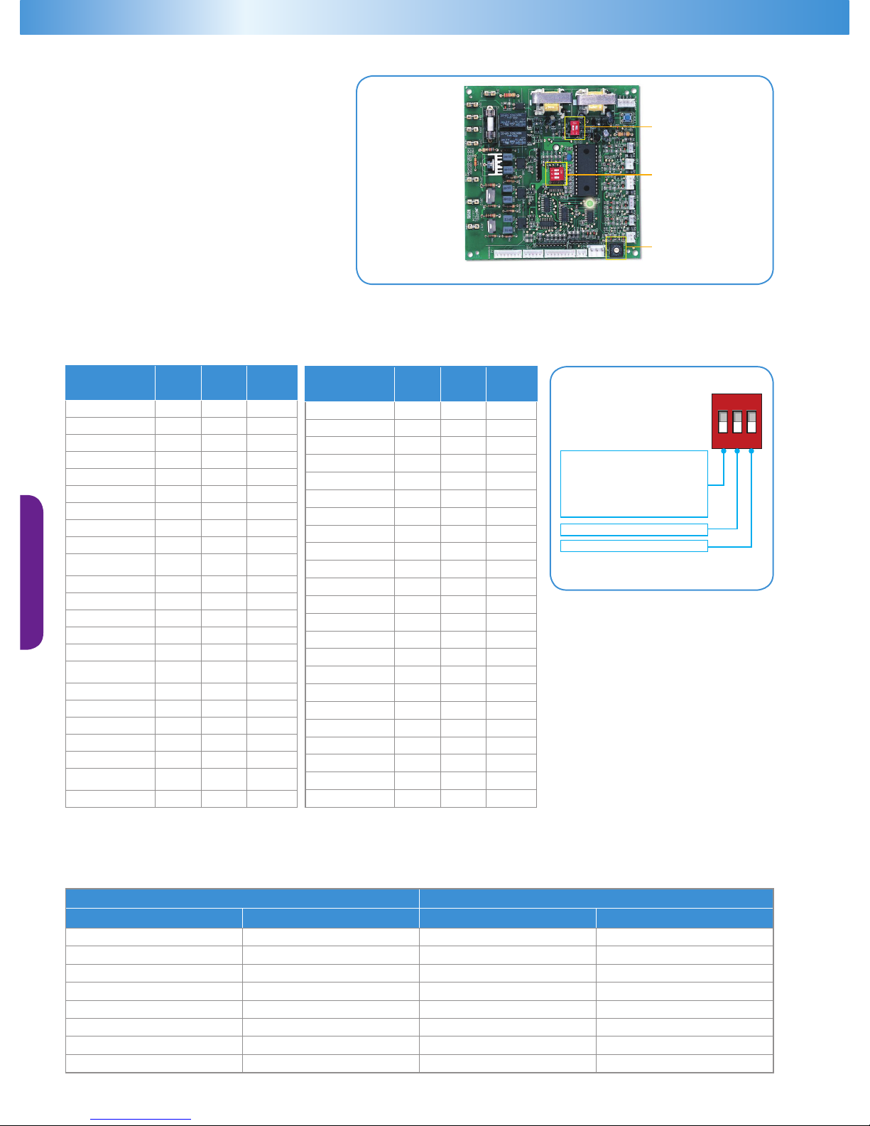
Defrost Module Function Set
Time of Defrost Time of Defrost Interval
Rotary Switch1 Time(min) Rotary Switch2 Time(hours)
0 0 0 0
1 5 1 1
2 10 2 2
3 15 3 3
4 20 4 4
5 25 5 5
6 30 6 6
7 35 7 7
E2 Control Board Dip
Switch Setting
The E2 control board has two dip switches (2-bit
and 3-bit) and one rotary switch. The rotary switch
and the 2-bit dip switch are used in combination
to select the compressor used on the unit. The
selected compressor relates to the over-current-
limit for the specied unit. The 3-bit dip switch is
used if the customer chooses to use the E2 control
for evaporator fan control. Fig 15 shows the dip
switches and rotary switch in the E2 control board.
2-Bit Dip Switch
3-Bit Dip Switch
Rotary Switch
E2 Control Board
Figure 15: E2 Controller
E2 Control Board - Rotary Switch And Dip Switch Setting (ZX-MT & ZXL-LT)
Model
Rotary
Switch
3-Bit
No. 3
2-Bit
1/2
ZX0200/E-PFJ 7 OFF ON/ON
ZX0250/E-PFJ 8 OFF ON/ON
ZX0300/E-PFJ 9 OFF ON/ON
ZX0400/E-PFJ A OFF OFF/OFF
ZX0200/E-TFD 1 OFF ON/ON
ZX0300/E-TFD 2 OFF ON/ON
ZX0400/E-TFD 3 OFF ON/ON
ZX0500/E-TFD 4 OFF ON/ON
ZX0600/E-TFD 5 OFF ON/ON
ZX0750/E -
760/E-TFD
6 OFF ON/ON
ZX0200/E-TF5 1 ON ON/ON
ZX0300/E-TF5 2 ON ON/ON
ZX0400/E-TF5 3 ON ON/ON
ZX0500/E-TF5 4 ON OFF/OFF
ZX0600/E-TF5 5 ON OFF/OFF
ZX0750/E -
760/E-TF5
6 ON OFF/OFF
ZX0200/E-TF7 7 ON ON/ON
ZX0300/E-TF7 8 ON ON/ON
ZX0400/E-TF7 9 ON ON/ON
ZX0500/E-TF7 A ON ON/ON
ZX0600/E-TF7 A ON ON/ON
ZX0750/E -
760/E-TF7
B ON ON/ON
ZXL0200/E-TFD 1 OFF ON/ON
Notes: The settings given in the table are pre-set at
the factory for new units.
ON
1 2 3
OFF: Evaporator fan ON/OFF logic is same
as compressor and this is the factory
default setting.
ON: Evaporator fan will be ON for all time
irrespective of whether the compressor is
turned ON or OFF
Not applicable
Use setting in the table
Model
Rotary
Switch
3-Bit
No. 3
2-Bit
1/2
ZXL0250/E-TFD 2 OFF ON/ON
ZXL0300/E-TFD 3 OFF ON/ON
ZXL0350/E-TFD 4 OFF ON/ON
ZXL0400/E-TFD 5 OFF ON/ON
ZXL0500/E-TFD 6 OFF ON/ON
ZXL0600/E-TFD 7 OFF ON/ON
ZXL0750/E-TFD 8 OFF ON/ON
ZXL0200/E-TF5 1 ON ON/ON
ZXL0250/E-TF5 1 ON ON/ON
ZXL0300/E-TF5 2 ON ON/ON
ZXL0350/E-TF5 3 ON OFF/OFF
ZXL0400/E-TF5 4 ON OFF/OFF
ZXL0500/E-TF5 5 ON OFF/OFF
ZXL0600/E-TF5 6 ON OFF/OFF
ZXL0750/E-TF5 7 ON OFF/OFF
ZXL0200/E-TF7 8 ON ON/ON
ZXL0250/E-TF7 8 ON ON/ON
ZXL0300/E-TF7 9 ON ON/ON
ZXL0350/E-TF7 A ON ON/ON
ZXL0400/E-TF7 B ON ON/ON
ZXL0500/E-TF7 C ON ON/ON
ZXL0600/E-TF7 D ON ON/ON
ZXL0750/E-TF7 D ON ON/ON
Page 19
ZX Platform Condensing Unit
16
Fault Type Trip Set Point E2 Control Actions Auto Resets Possible Error And Solution
Reverse Phase /
Loss Of Phase
(3 Phase Only)
Incorrect voltage
Sequence
- Lockout unit
- Display Incorrect Phase Sequence on
diagnostic
- Initiate Buzzer/ Dialer Relay
Unit will not
start unless it is
wired correctly
- Change voltage sequence at
circuit break.
- Check voltage sequence of the
compressor;
Fresh Start
If power is reset,
ambient < 35°C
or compressor off>
1 hour & signal for
compressor start
- Compressor runs 3 sec and stops 20 sec
- After 3 cycles, compressor runs
continuously.
- Display fresh start on diagnostic
Auto start
- Nothing is wrong, just wait till
compressor runs continuously.
High Pressure
Tri p
Contact Open At
3.0 ±0.15Mpa
Contact Close At
2.4±0.15Mpa
- Stop the unit
- Display HP trip on diagnostic
- Display waiting to restart on diagnostic
- Auto start the unit after 3 minutes
- Lockout unit if 6 trips in less than 1 hour
- Display HP lockout on diagnostic
-Initiate Buzzer/ Dialer Relay
5 Auto starts in
1 Hour
- Check whether HP cutout is
functioning or is connected to
control board;
-Check whether condenser fan can
run;
-Check if the liquid line solenoid
valve and liquid service valve are
open.
Low Pressure Trip
(Only in Med Temp
Unit)
Contact Open At
0.1±0.05Mpa
Contact Close At
0.2 ±0.05Mpa
-Stop the unit
- Display LP trip on diagnostic
- Display waiting to restart on diagnostic
- Auto start the unit after 3 minutes
Auto Start
- Check whether evaporator need
defrosting
- Check that return gas service valve
is open;
- Check that LP cutout is functioning
or is connected to control board
(1 second)-
>
- Power On
- Unit Identification Code
- Software Version No.
(3 seconds)-
>
(3 seconds)-
>
“F”-With OD Fan Speed Control; “-”- W/O OD Fan Speed Control
“-” - ZX; “L” - ZXL
LED 2
LED 1
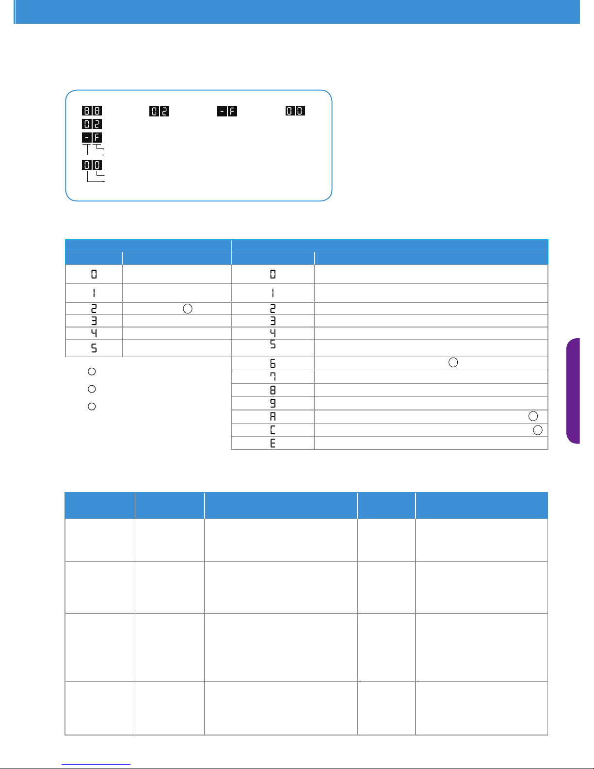
Diagnostic Initialization Message (ZX-MT and ZXL-LT)
When the unit is initially powered on, the diagnostic module will show the following signals.
E2 Controller Trip Set Points and Actions (ZX-MT and ZXL-LT Units)
LED1-Unit Status LED2-Error/Warning Code
Display Status Display Error/Warning
Idle (Stop When Reach To
Set-point)
No error/warning
Run
Compressor Phase Error (Wrong Phase Sequence/Loss of
Phase)
About To Start Compressor Inside Thermal Protector Trip
Defrost Compressor Over Current
Stop Due to Error Overheat
Lockout Compressor High Pressure Cut Out
Compressor Low Pressure Cut Out
DLT Thermistors Failure
Ambient Temperature Sensor Failure
Mid-coil Temperature Sensor Failure
PHE Vapor In Temperature Sensor Failure or Over Range
PHE Vapor Out Temperature Sensor Failure or Over Range
System Liquid Flood Back Warning
Notes: New start, normal start by program and any
start request delay
LP Cutout”signal is not applicable in ZXL
condensing unit.
PHE Vapor In/Out temperature sensor is
not applicable in ZX medium temperature
condensing unit.
1
2
3
1
Diagnostic messaging - LED denition (ZX-MT and ZXL-LT)
2
3
3
Page 20

17
E2 Controller Trip Set Points and Actions (ZX-MT and ZXL-LT Units) continuation
Fault Type Trip Set Point E2 Control Actions Auto Resets Possible Error And Solution
Discharge Gas
Overheat
Discharge
Temperature Over
132°C
- Stop the unit
- Display DLT trip on diagnostic
- Display waiting to restart on diagnostic
-Auto start the unit after 3 minutes
- Lockout unit if 6 trips in less than 1 hour
- Display DLT overheat lockout on
diagnostic
- Initiate Buzzer/ Dialer Relay
5 Auto starts in
1 Hour
- Check if liquid line sight glass is
full;
- Check whether EXV is functioning
and connected to control board
Over Current
Set Based On
Compressor
- Stop the unit
- Display over current trip on diagnostic
- Display waiting to restart on diagnostic
-Auto start the unit after 3 minutes
- Lockout unit if 6 trips in less than 1 hour
- Display over current lockout on
diagnostic
- Initiate Buzzer/ Dialer Relay
5 Auto starts in
1 Hour
- Check rotary switch, make sure it
is on the right position according
to unit model;
- Check oil level through
compressor sight glass (Low temp
unit only);
Electrical Failure
Compressor not
drawing current
after compressor
contactor
organized
- Display compressor protector trip on
diagnostic
- Initiate Buzzer/ Dialer Relay -Auto start
when protector reset, turn off buzzer/
Dialer
Auto start
-Check whether contactor is pulledin. If not, check wiring of contactor
coil;
-Check wiring, make sure
compressor is connected to
contactor, and is powered;
-Compressor motor thermal
protector trips, wait till it reset.
Compressor
Rapid Cycling
Minimum 3
minutes OFF time
between starts
-Delay comp start, if minimum off time is
less than 3 min
-Display about to turn on diagnostic
Auto start
-Compressor start signal is active
when unit just stops; the only thing
needed to do is to wait until unit
starts.
Discharge Line
And Coil In Tem-
perature Sensors
Failure
A) Actual
DLT>160°C
(B) DLT Sensor fails
and Actual DLT>
80°C
(C) Both coil-in
and DLT sensor fail
(short circuit)
(D) Coil in sensor
fails(short) and
actual DLT<73°C
(Only Low Temp Unit)
-Stop the unit
-Display DLT sensor failure on the
diagnostic
-Display waiting to restart on diagnostic
-Auto start the unit after 3 minutes
-Lockout unit if 6 trips in less than 1 hour
-Display DLT sensor failure lockout on
diagnostic
-Initiate Buzzer/ Dialer Relay
5 Auto start in
1 Hour
-Check if liquid sight glass is full. If
not, system must have leakage at
somewhere;
-Check whether DLT sensor is
connected to control board;
-Check whether DLT sensor is OK. If
not, replace it with a good one;
-Check whether Coil In sensor is OK.
If not, replace it with a good one
(Only Med Temp Unit)
-Display DLT sensor failure on diagnostic
-Continue to run the unit on default
mode
Run
(A) Coil in sensor
fails(open) and
actual DLT<73°C
(B) Both coil-in
and DLT sensor fail
(open circuit)
(Both Low and Med Temp Unit)
-Display DLT sensor failure on diagnostic
-Continue to run the unit on default
mode
Run
-Check whether the sensors are
connected to control board;
-Check whether Coil-in is OK. If not,
replace it with a new one;
-Check whether compressor is
having excessive ood back.
Ambient Tem-
perature Sensor
Failure
Ambient sensor
reads <-30°C or
>63°C
-Display ambient temp sensors failure on
diagnostic
-Continue to run the unit on default
mode
Run
-Check whether actual Ambient
temperature is out of range;
-Check whether Ambient sensor is
OK and connected to control board.
Condenser
Mid-Coil Sensor
Failure
Mid coil sensor
reads <-30°C or
>63°C
-Display mid coil temp sensors failure on
diagnostic
-Continue to run the unit on default
mode
Run
-Check whether actual mid-coil
temperature is out of range;
-Check whether mid-coil sensor is
OK and connected to control board.
PHE Vapor In
Sensor Failure
(Only Low Temp
Unit)
Vapor In sensor
reads <-16°C or
>73°C
-Display sensor error on diagnostics
-Continue to run the unit on default
mode
Run
-Check whether actual temperature
is out of range;
-Check whether the sensor is
connected to control board;
-Check whether the sensor is
mounted at the right position;
-Check whether the sensor is in heat
isolation material;
-Check whether the sensor has
failed.
PHE Vapor Out
Sensor Failure
(Only Low Temp
Unit)
Vapor out sensor
reads <-16°C or
>73°C
-Display sensor error on diagnostics
-Continue to run the unit on default
mode
Run
Page 21
ZX Platform Condensing Unit
18
12
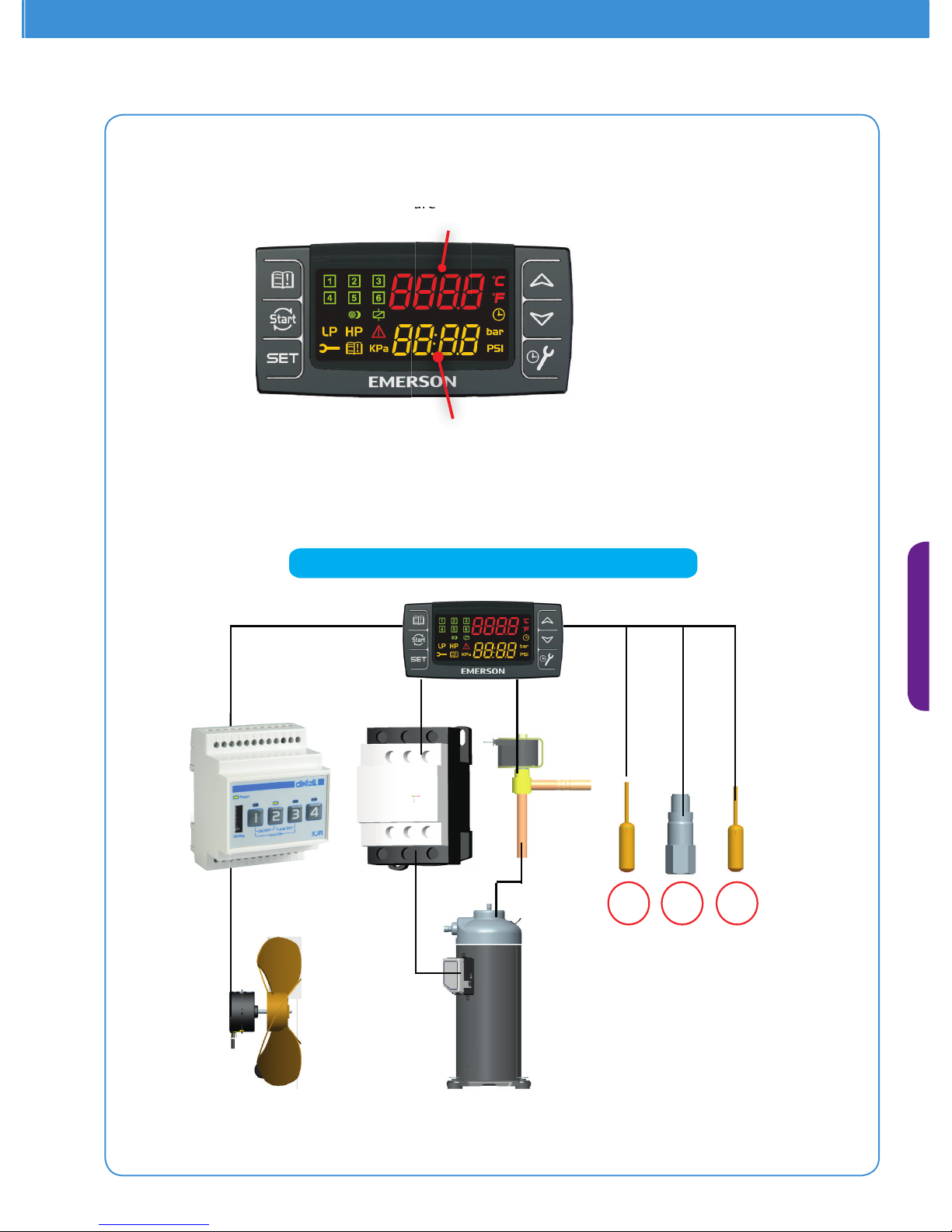
Modulated Fan
3
Emerson Controller On ZXD
ZXD Controller Assembly
Program Mode: browses parameter codes or
increase value
Hot Key Insert : Hot key programming
procedure
INFO Menu: Press and release it to access
INFO Menu
Program Mode: below parameter codes or
decrease value
Maintenance /Clock
Suction pressure
Suction temperature display
Condenser pressure
Condenser temperature display
Enter Alarm
Manual Restart
Setup Menu
rature
d
er press
u
1: Mid-Coil Temp Sensor
2: Suction Pressure Transducer
3: Discharge Temp Sensor
Page 22
19
ZXD Electronic Controller
ZXD Condensing Unit BOM
Electronic Controller Parts
ZXD BOM
450 451 461
Digital scroll compressor controller
Fan speed controller
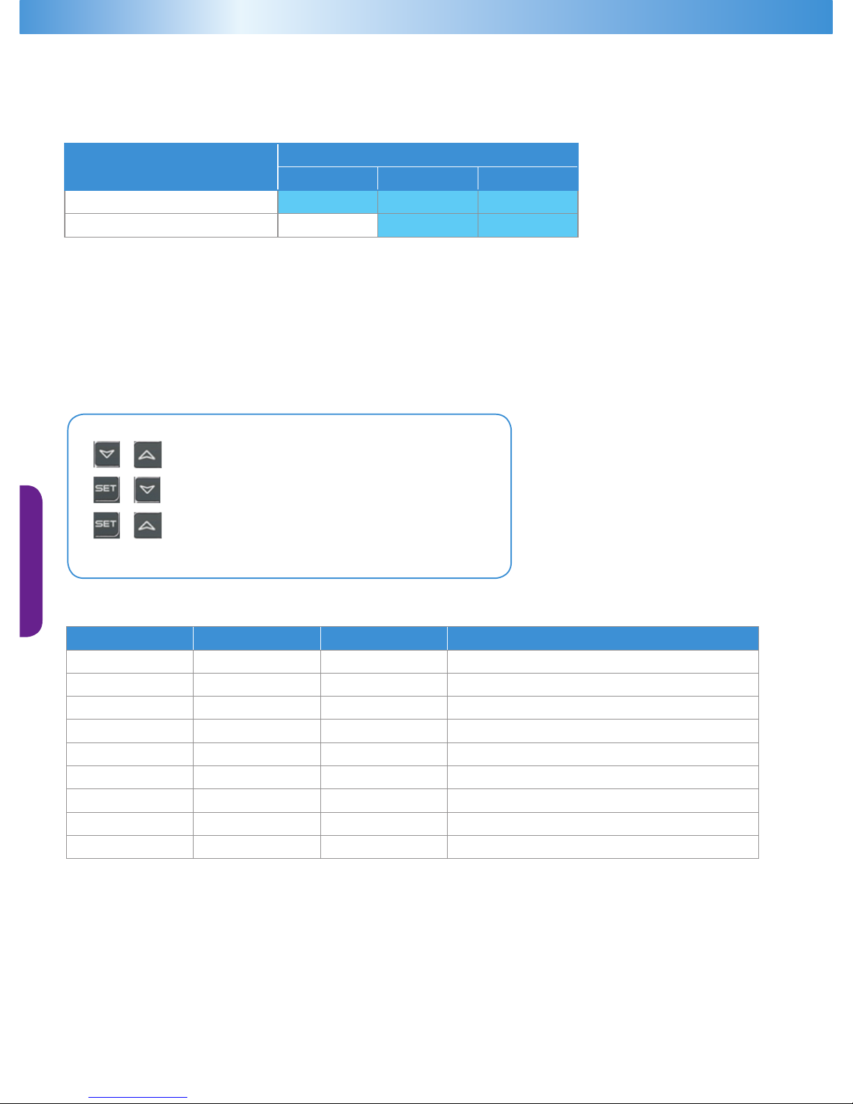
The controller has been pre-programmed with a number of parameter values that are most likely correct. Individual installation
requirements, however, may make it necessary to alter parameter settings.
The control target of the compressor controller is to maintain the suction pressure (or saturated suction temperature) at a dened
value by varying the available compressor capacity.
The control target of the fan speed controller is to maintain the average condenser mid coil temperature and hence the average
discharge pressure at a dened value. This is achieved by varying the fan speed. The setpoint can be altered using the SEtF parameter.
Keyboard
+ Press Together for 3 seconds to Lock and unlock keyboard
+ Press together for 3 seconds to enter programming mode
+ Exit programming mode or wait 30 seconds
Pre-Set Parameters
Parameter Value Unit Description
SEtC -6 °C Evaporation temperature set point
SEtF 25 °C Fan speed control condenser mid-point temperature
dEU tMp - Saturated Temperature measurement
CF °C - Temperature unit
PMU Bar - Pressure unit
dSP1 p2 - Upper LED display – condensing temp.
dEU1 tMp - Upper LED default - temperature
dSP2 p1 - Lower LED default display – Suction Pressure
dEU2 prs - Lower LED default - pressure
Warning: Before changing set points, installer must check refrigerant type, measured value units for compressors and fans.
Example: FtyP(Refrigerant type), dEU(Measured value units), LSE/HSE (limitation of set values)
Page 23
ZX Platform Condensing Unit
20
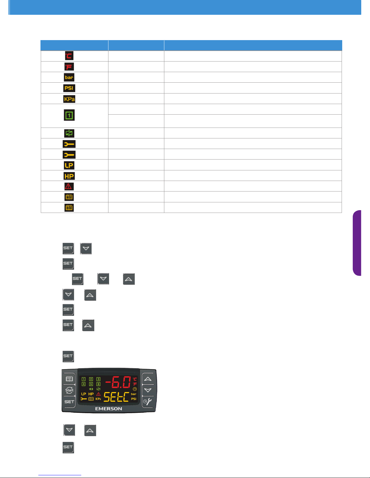
LED Function Description
ON
Temperature unit, Celsius degrees
ON Temperature unit, Fahrenheit degrees
ON Pressure unit for display
ON Pressure unit for display
ON Pressure unit for display
ON Digital scroll compressor power on
Flashing
1 Hz : Digital scroll compressor is waiting to start
2 Hz : Digital input alarm for digital scroll compressor or maintenance status
ON Solenoid valve of digital scroll compressor is energized
ON Maintenance menu has been entered
Flashing One or more compressor has been in maintenance status
ON Mechanical low pressure switch alarm
ON Mechanical high pressure switch alarm
ON Unit is in Alarm status
ON There is no new alarm
Flashing A new alarm has occurred
Icons on LED Display
To reset an alarm: Press the SET key until rSt is displayed in the lower display
To reset all alarms: Press and hold the SET key for 10s.
Refrigerant Setting
+ Press for 3 sec to enter programming mode
value will start blinking
Use
and and to enter password 3210
or to change refrigerant
store new value and move to following parameter
+ to Exit or wait 30 sec to Exit
Initial setting of setpoint for suction pressure or saturated suction temperature
press for more than 2 sec
or to change set value within 30 sec
press to memorize new set value, then SetF (fan speed control setpoint) will be displayed automatically
SEtC value
Flashing
Page 24
21
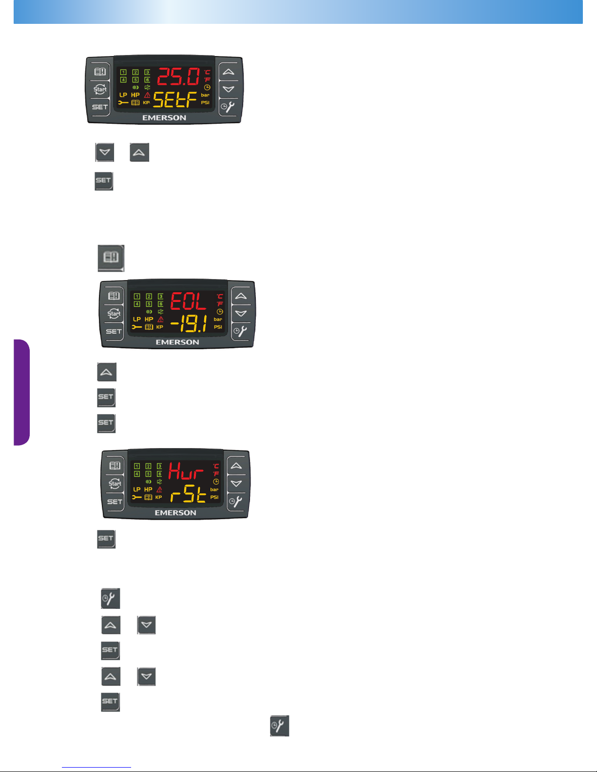
or to change set value within 30 sec
press to memorize new value and Exit, or wait for 30 sec without press any key to memorize value and Exit
Press or wait for 30 sec
SEtC value
Flashing
How to Check Alarm History
Press alarm key
SEtC value
Flashing
Press to nd other alarms from most recent records
Press to see that alarm’s activation hours
To delete alarm press and hold until ‘rSt’ is showing on lower LED display
SEtC value
Flashing
Press 10 sec to erase alarm. Running alarm cannot be erased
To Disable Controller During Service Work on ZXD
Press for 3 sec
or to select parameter
parameter value will start blinking
or to change set values from On to Off
press to memorize new set value, then automatically next parameter will be displayed
press it or wait for 30 sec
Page 25
ZX Platform Condensing Unit
22
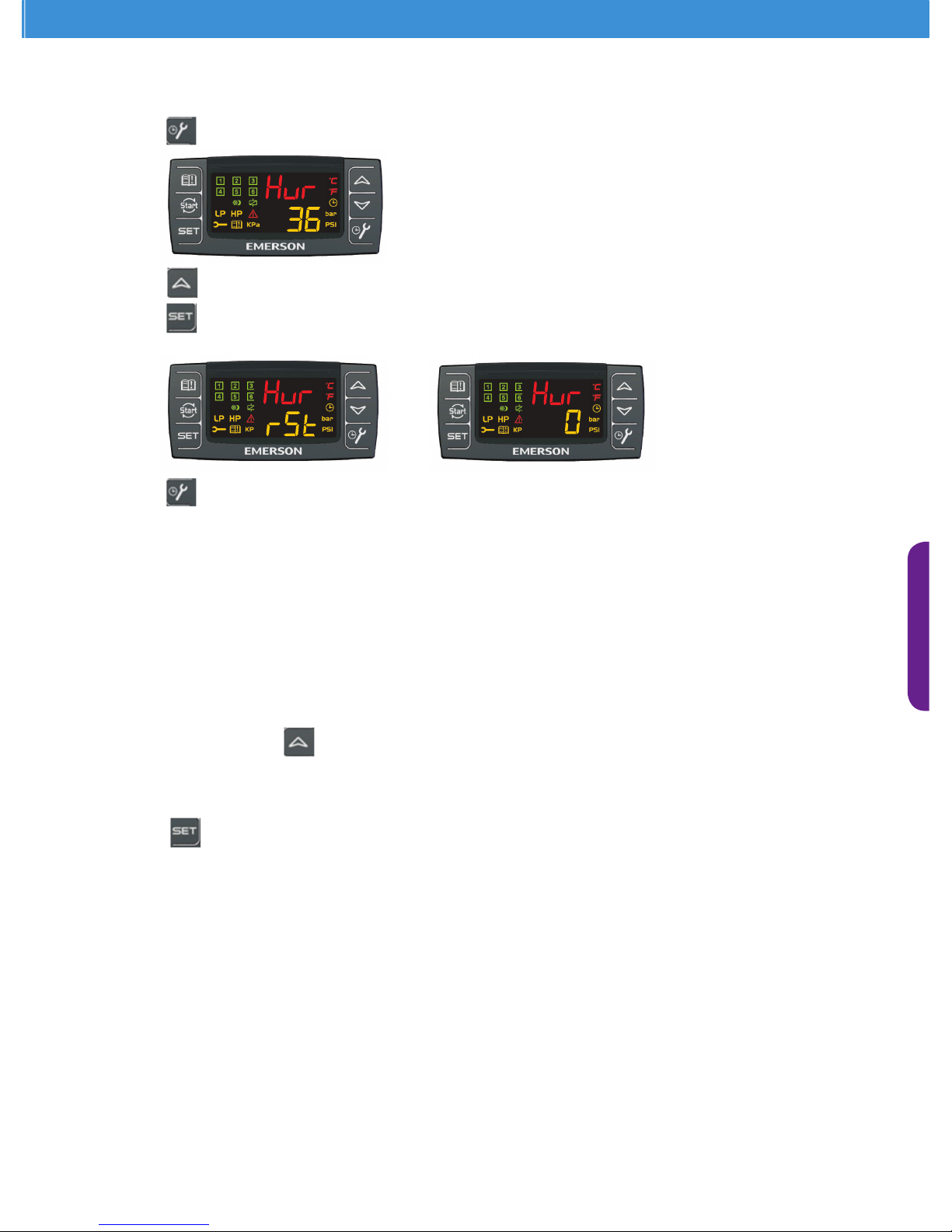
Check Running Hours of Each Compressor and Reset Operation Time After Compressor Replacement
Press and release
SEtC value
Flashing
Press to select compressor number
Press and hold SET key
SEtC value
Flashing
SEtC value
Flashing
Press or wait for 30 sec
Reset Parameters by Using ‘Hot Key’
• Power off the unit
• Insert the factory programmed ‘Hot Key’ into the 5pin connecter
• Power on the unit
• Factory programmed parameters will be copied from “Hot Key” to controller
• ‘doL’ message will blink and then ashing ‘End’ will be shown on the LED.
• After 10sec, unit will run with new parameters
• Remove ‘Hot Key’ from electronic controller
Save Parameters in ‘Hot Key’
• Power on the unit
• Insert ‘Hot key’ and press
key
• Factory programmed parameters will be copied to ‘Hot Key’
• ‘uPL’ message will blink and then ashing ‘End’ will be shown on the LED.
• Press
key and ‘End’ will stop ashing
• Power off unit and remove ‘Hot key’ from controller
• Power on unit
Digital scroll compressor controller has been specially developed for Emerson ZXD condensing unit. This controller is only intended
for use in Emerson ZXD condensing units, therefore Emerson has no responsibility of any use on other condensing unit.
Page 26
23
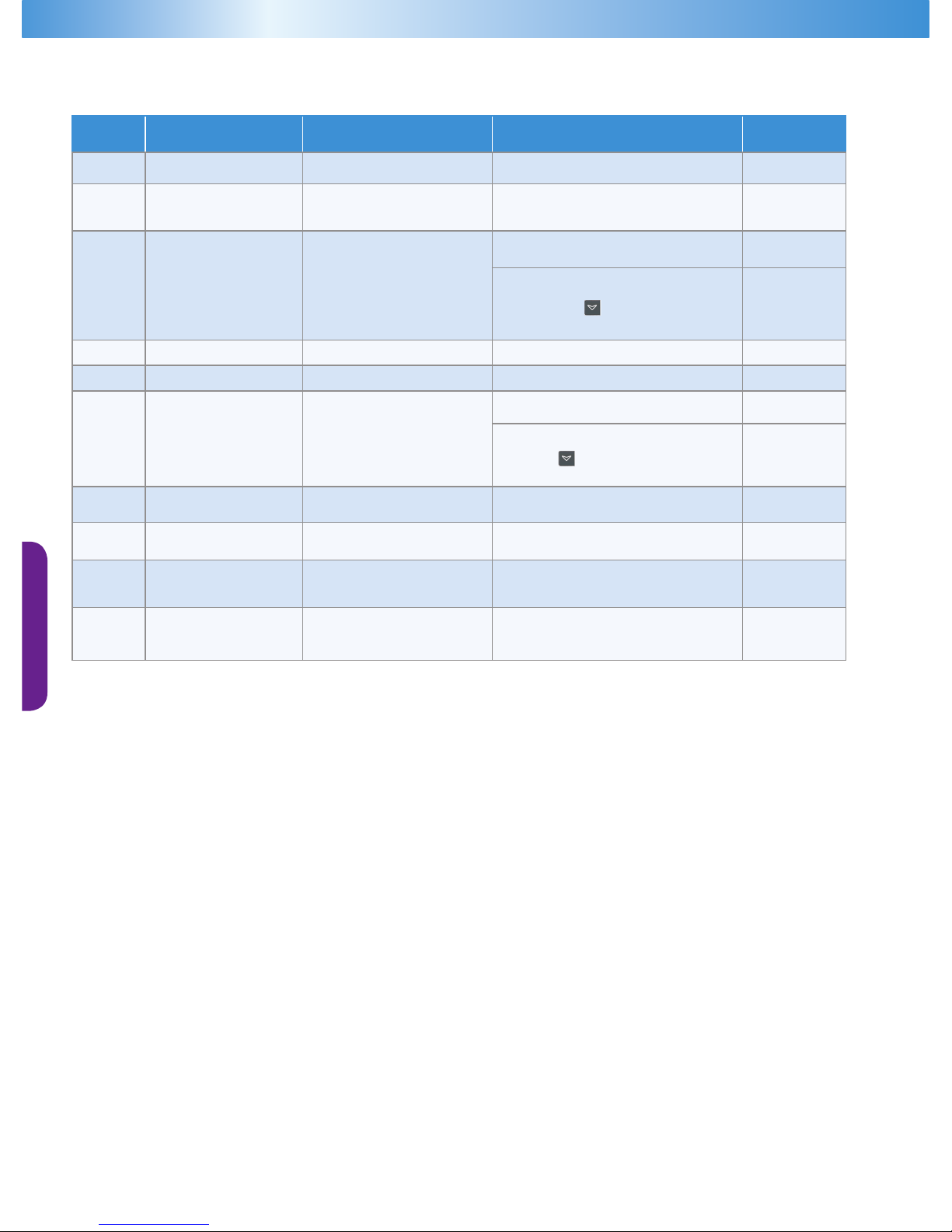
Alarm Messaging - Digital Scroll Controller (ZXD)
Alarm
Mode
Set Points Controller Actions Reset Remarks
dtL
DLT >= dtL after
dLd time delay
- Compressors are turned off Auto reset when DLT < dtL-dLH
DLT
E01L
Low pressure is lower
than ELP
(Level 3 Parameter)
- Compressors are turned off
- Fans are unchanged
Auto reset when LP >= ELP(Level 3)
LP
E0L
Mechanical LP
switch opens
- Compressors are turned off
- Fans are unchanged
Auto reset when Number of
activations < PEn in PEi time
LP
Manual reset when Number of
activations >= PEn in PEi time
- Press
key for 3 sec or
- Turn off and on the unit
LP
C-LA
LP < LAL
- Signaling only
Auto reset when LP = LAL + delta (0.3bar)
LP
C-HA
LP >= HAL
- Signaling only
Auto reset when LP = HAL -delta (0.3bar)
LP
E0H
Condensing Temperature
High
- Compressors are turned off Fans are turned on
Auto reset when Number of activations
< PEn in PEi time
Cond Mid Temp.
Manual reset when Number of activations
>= PEn in PEi time
- Press
key for 3 sec or - Turn off
and on the unit
Cond Mid
F-HA
HP >= HAF
- HFC = yes, compressor are
turned off
Auto reset when HAF + delta (0.3bar)
Cond Mid Temp.
P1
Suction Transducer
failure or out of range
- Compressors are activated
according to SPr or PoPr
Auto reset when probe is normal
LP
P2
Condenser Mid Coil
Sensor failure or out
of range
- Fans are activated according
to FPr
Auto reset when probe is normal
Cond Mid Temp.
P3
Discharge Temp Sensor
failure or out of range
-The functions related to No.3
probe are disabled
Auto reset when probe is normal
DLT
DLT : Discharge line temperature
LP : Low pressure
HP : High pressure
Page 27
ZX Platform Condensing Unit
24
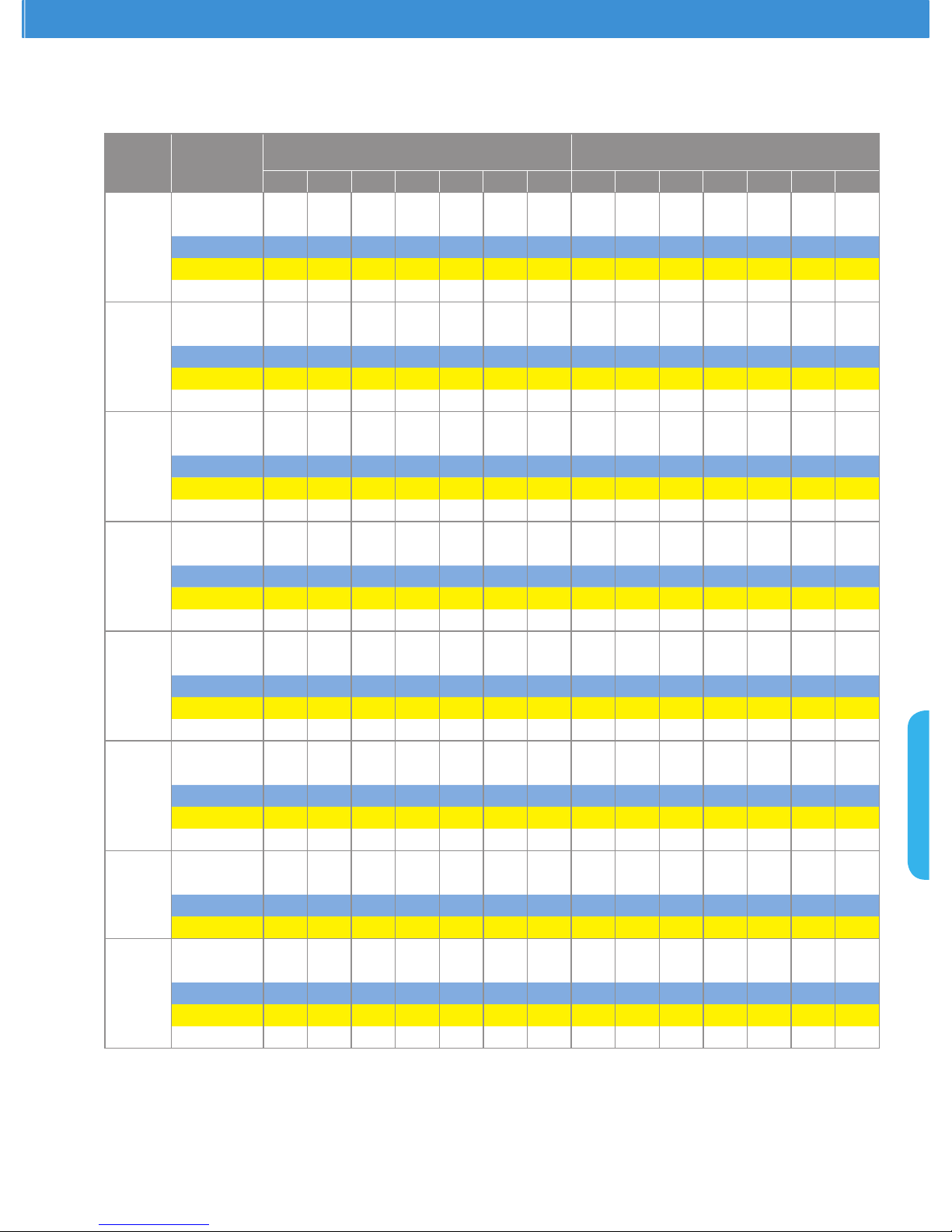
ZX Family: Medium Temperature
Capacity and Power (kW) at 50 Hz - PFJ/TFD
R22 - 50 Hz
Model
Ambient
Temperature
(oC)
Capacity
Evaporating Temperature (
o
C)
Power
Evaporating Temperature (oC)
-15 -10 -5 0 5 10 12 -15 -10 -5 0 5 10 12
ZX0200
27 2.84 3.61 4.18 4.95 5.87 7.03 7.45 1.33 1.37 1.41 1.47 1.53 1.70 1.79
32 2.65 3.33 4.01 4.75 5.61 6.54 6.96 1.45 1.50 1.58 1.64 1.71 1.84 1.88
38 2.38 3.11 3.81 4.55 5.37 6.19 6.68 1.62 1.74 1.83 1.87 1.91 2.03 2.08
43 1.93 2.74 3.48 4.23 5.06 5.99 6.33 1.78 1.83 1.95 2.05 2.11 2.20 2.25
48 1.68 2.30 3.18 3.87 4.69 5.51 5.80 2.21 2.31 2.44 2.51 2.54 2.55 2.64
ZX0250
1
27 2.72 3.64 4.39 5.09 5.83 6.71 8.36 1.79 1.90 1.94 1.95 1.95 1.98 2.12
32 2.56 3.45 4.18 4.83 5.52 6.33 7.87 2.02 2.14 2.18 2.19 2.19 2.21 2.34
38 2.11 3.00 3.71 4.33 4.98 5.74 7.18 2.35 2.47 2.51 2.51 2.51 2.52 2.64
43 1.62 2.53 3.25 3.88 4.51 5.25 6.64 2.67 2.78 2.83 2.83 2.82 2.83 2.93
48 2.08 2.83 3.48 4.13 4.86 7.37 6.23 3.15 3.19 3.18 3.17 3.17 2.29 3.25
ZX0300
27 4.30 5.20 6.28 7.57 9.09 10.22 10.80 1.95 2.04 2.17 2.20 2.23 2.43 2.49
32 4.12 4.90 5.95 7.28 8.69 9.79 10.31 2.10 2.20 2.32 2.34 2.46 2.70 2.77
38 3.68 4.62 5.65 6.85 8.29 9.06 9.63 2.37 2.48 2.59 2.60 2.76 3.06 3.12
43 3.27 4.22 5.27 6.50 7.97 8.63 9.08 2.64 2.75 2.84 2.94 3.04 3.32 3.36
48 2.40 3.55 4.65 5.67 6.86 7.97 8.50 2.98 3.18 3.28 3.35 3.50 3.64 3.69
ZX0400
27 5.98 7.20 8.57 10.03 11.54 13.82 14.64 2.64 2.71 2.83 2.98 3.08 3.34 3.36
32 5.46 6.73 8.13 9.62 11.16 13.01 13.85 2.81 2.90 3.06 3.19 3.33 3.68 3.68
38 4.72 6.01 7.42 8.93 10.48 12.09 13.04 3.08 3.27 3.39 3.49 3.65 4.09 4.07
43 4.09 5.37 6.78 8.27 9.80 11.61 12.25 3.29 3.52 3.68 3.80 3.95 4.38 4.39
48 3.55 4.50 6.20 7.57 9.08 10.68 11.23 4.16 4.46 4.49 4.72 4.80 5.07 5.18
ZX0500
2
27 7.13 8.76 10.44 12.22 14.12 17.28 18.22 2.88 3.03 3.18 3.29 3.47 4.16 4.28
32 6.77 8.31 9.96 11.72 13.68 16.62 17.47 3.37 3.35 3.57 3.67 3.97 4.50 4.58
38 6.24 7.69 9.28 11.06 13.06 15.31 16.34 3.77 3.87 4.07 4.27 4.47 4.98 5.10
43 5.44 6.80 8.36 10.15 12.21 14.60 15.47 4.27 4.27 4.47 4.66 4.96 5.46
5.56
48 3.96 5.80 7.62 9.49 11.47 13.49 14.40 5.14 5.21 5.44 5.61 5.80 6.01 6.04
ZX0600
2
27 8.50 10.41 12.49 14.72 17.66 19.64 20.60 3.51 3.70 3.88 4.16 4.43 4.98 5.32
32 7.71 9.93 11.71 13.94 16.30 18.87 20.10 3.88 4.07 4.25 4.43 4.71 5.29 5.47
38 6.81 8.42 10.57 12.85 15.26 17.77 18.92 4.34 4.53 4.71 4.90 5.08 5.86 5.98
43 5.91 7.23 9.40 11.78 14.26 16.33 17.86 4.90 5.17 5.45 5.64 5.73 6.57 6.66
48 4.97 7.00 9.25 11.15 13.08 15.09 16.06 6.02 6.22 6.46 6.69 6.96 7.22 7.45
ZX0750
2
27 10.03 12.20 14.41 17.23 20.87 4.34 4.54 4.76 4.98 5.22
32 9.45 11.24 13.90 16.63 20.21 4.77 4.95 5.19 5.51 5.91
38 8.83 10.85 13.25 15.50 19.42 5.36 5.53 5.83 6.25 6.80
43 8.18 10.00 12.29 14.30 18.49 5.95 6.10 6.43 6.93 7.62
ZX0760
2
27 10.23 12.44 14.70 17.60 21.29 25.49 27.01 4.25 4.45 4.66 4.88 5.12 5.47 5.64
32 9.64 11.46 14.18 16.96 20.61 24.03 25.58 4.67 4.85 5.09 5.40 5.79 5.86 5.97
38 9.01 11.07 13.52 15.80 19.81 22.85 24.65 5.26 5.42 5.72 6.12 6.67 6.64 6.81
43 8.34 10.20 12.54 14.60 18.86 22.34 23.57 5.83 5.98 6.30 6.79 7.47 7.34 7.48
48 7.24 8.55 11.46 14.09 17.47 20.55 21.61 6.79 7.04 7.40 7.89 8.43 8.74 8.78
Notes: 1 Available on PFJ models only
2
Available on TFD models only
Based on a return gas temperature of 18.3°C.
Power includes condenser fan.
Ambient 38°C and 43°C are typical design conditions for unit selection.
Page 28
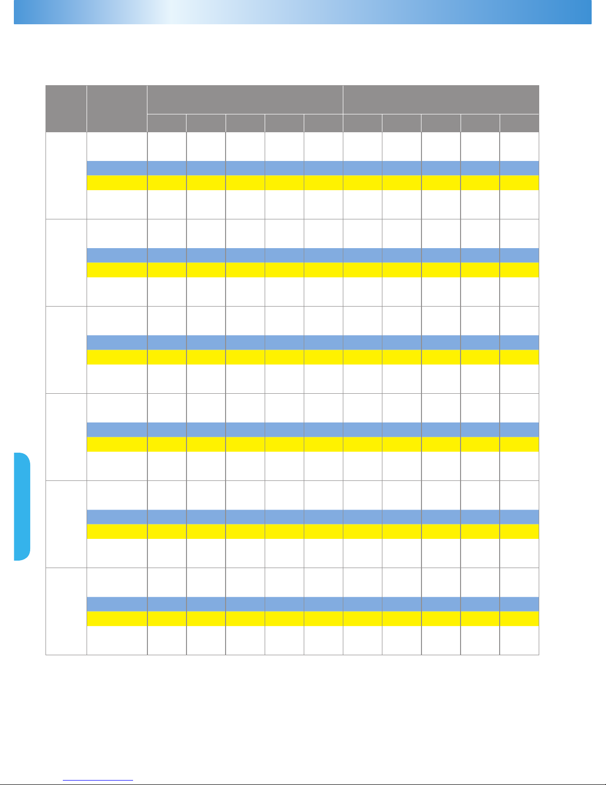
25
Model
Ambient
Temperature
(oC)
Capacity
Evaporating Temperature (
o
C)
Power
Evaporating Temperature (oC)
-15
-10
-5 0 5 -15 -10 -5 0 5
ZX0200
27 3.62 4.42 5.36 6.43 7.59 1.69 1.71 1.69 1.69 1.71
32 3.41 4.22 5.17 6.20 7.29 1.89 1.91 1.90 1.89 1.90
38 2.88 3.77 4.75 5.78 6.84 2.13 2.17 2.17 2.17 2.18
43 2.20 3.19 4.24 5.31 6.38 2.35 2.41 2.42 2.43 2.45
48 1.30 2.43 3.58 4.73 5.84 2.59 2.67 2.71 2.73 2.75
50 0.88 2.07 3.27 4.46 5.60 2.69 2.78 2.83 2.85 2.89
ZX0300
27 5.12 6.20 7.29 8.90 10.54 2.42 2.53 2.69 2.73 2.77
32 4.91 5.84 6.98 8.48 10.00 2.60 2.73 2.88 2.90 3.05
38 4.39 5.51 6.53 7.96 9.38 2.94 3.08 3.21 3.22 3.42
43 3.90 5.03 5.94 7.35 8.74 3.27 3.41 3.52 3.65 3.77
48 2.86 4.23 5.01 6.45 7.86 3.70 3.94 4.07 4.15 4.34
50 2.45 3.12 4.51 5.98 7.40 3.86 4.16 4.29 4.36 4.57
ZX0400
27 7.36 8.83 10.52 12.37 14.31 3.25 3.35 3.52 3.75 4.02
32 7.06 8.54 10.21 12.02 13.92 3.55 3.63 3.79 4.01 4.28
38 6.37 7.87 9.55 11.34 13.20 4.05 4.11 4.26 4.48 4.75
43 5.62 7.16 8.86 10.66 12.50 4.55 4.60 4.73 4.95 5.22
48 4.82 6.41 8.14 9.96 11.81 5.09 5.12 5.25 5.46 5.74
50 4.50 6.12 7.87 9.70 11.55 5.30 5.33 5.46 5.67 5.95
ZX0500
27 8.55 10.51 12.53 14.66 16.95 3.54 3.72 3.91 4.05 4.27
32 8.12 9.97 11.95 14.06 16.42 4.15 4.13 4.39 4.52 4.88
38 7.49 9.23 11.14 13.28 15.68 4.64 4.76 5.00 5.25 5.49
43 6.53 8.16 10.03 12.18 14.65 5.25 5.25 5.49 5.74 6.10
48 4.75 6.96 9.14 11.39 13.76 6.33 6.40 6.69 6.90 7.13
50 4.04 6.48 8.79 11.07 13.41 6.76 6.87 7.16 7.37 7.55
ZX0600
27 10.20 12.49 14.99 17.66 21.19 4.39 4.62 4.85 5.20 5.54
32 9.25 11.92 14.05 16.73 19.56 4.85 5.08 5.31 5.54 5.89
38 8.17 10.10 12.68 15.42 18.31 5.43 5.66 5.89 6.12 6.35
43 7.09 8.68 11.28 14.14 17.11 6.12 6.47 6.81 7.04 7.16
48 5.96 8.40 11.10 13.38 15.70 7.53 7.77 8.07 8.37 8.70
50 5.51 8.29 11.03 13.08 15.13 8.09 8.16 8.44 8.75 9.00
ZX0750
27 11.25 14.06 16.61 19.89 24.05 5.10 5.34 5.59 5.86 6.14
32 10.60 12.95 16.02 19.16 23.29 5.60 5.82 6.11 6.48 6.95
38 9.91 12.51 15.28 17.85 22.38 6.31 6.51 6.86 7.35 8.00
43 9.18 11.53 14.17 16.50 21.31 7.00
7.17 7.56 8.15 8.96
48 7.96 9.66 12.95 15.92 19.74 8.15 8.45 8.88 9.47 10.12
50 7.48 8.92 12.46 15.69 19.11 8.61 8.96 9.41 10.00 10.58
Note: Power include condenser fan.
Ambient 38°C and 43°C are typical design conditions for unit selection.
ZX Family: Medium Temperature
Capacity and Power (kW) at 60 Hz - TF5/TF7
R22 - 60 Hz
Page 29
ZX Platform Condensing Unit
26
ZX Family: Medium Temperature
Capacity and Power (kW) at 50 Hz - PFJ/TFD
R404A/R507 - 50 Hz
Model
Ambient
Temperature
(oC)
Capacity
Evaporating Temperature (
o
C)
Power
Evaporating Temperature (oC)
-20 -15 -10 -5 0 5 -20 -15 -10 -5 0 5
ZX020E
27 3.30 3.90 4.44 5.08 5.79 6.60 1.64 1.67 1.70 1.76 1.84 1.96
32 2.85 3.39 3.92 4.48 5.08 5.76 1.79 1.81 1.84 1.90 2.00 2.12
38 2.42 2.90 3.36 3.85 4.36 4.94 1.95 1.99 2.02 2.07 2.16 2.26
43 1.94 2.43 2.89 3.34 3.81 4.30 2.14 2.18 2.22 2.27 2.34 2.41
ZX025E
1
27 3.01 3.01 4.01 4.85 5.62 6.44 1.68 1.68 1.78 1.82 1.83 1.83
32 2.83 2.83 3.81 4.61 5.33 6.09 1.90 1.90 2.01 2.05 2.05 2.05
38 2.33 2.33 3.31 4.09 4.78 5.50 2.20 2.20 2.31 2.36 2.36 2.36
43 1.78 1.78 2.79 3.59 4.28 4.98 2.50 2.50 2.61 2.65 2.66 2.64
ZX030E
27 4.04 4.87 5.81 6.85 7.99 9.23 2.14 2.19 2.24 2.32 2.42 2.55
32 3.75 4.52 5.39 6.35 7.40 8.55 2.40 2.44 2.50 2.57 2.67 2.81
38 3.39 4.08 4.85 5.72 6.67 7.69 2.72 2.75 2.80 2.88 3.00 3.15
43 3.06 3.69 4.39 5.17 6.03 6.97 3.06 3.09 3.14 3.21 3.33 3.50
ZX040E
27 5.52 6.57 7.70 8.95 10.37 12.02 2.72 2.86 3.02 3.17 3.31 3.36
32 5.10 6.10 7.13 8.24 9.47 10.87 3.03 3.15 3.31 3.46 3.54 3.68
38 4.61 5.60 6.57 7.57 8.64 9.85 3.45 3.58 3.71 3.85 3.97 4.03
43 3.98 5.00 5.95 6.89 7.83 8.85 3.87 4.00 4.12 4.23 4.33 4.38
ZX050E
2
27 7.49 9.05 10.67 12.31 13.93 15.51 3.65 3.73 3.86 4.02 4.25 4.53
32 6.56 8.12 9.76 11.43 13.10 14.74 4.11 4.20 4.32 4.50 4.72 5.00
38 5.56 7.07 8.67 10.32 11.98 13.63 4.59 4.68 4.79 4.96 5.16 5.42
43 4.88 6.28 7.79 9.37 10.98 12.58 5.11 5.17 5.27 5.40 5.59 5.81
ZX060E
2
27 8.24 9.72 11.47 13.30 15.69 18.48 3.69 3.84 4.06 4.33 4.62 4.93
32 7.53 9.06 10.72 12.58 14.72 17.20 4.40 4.54 4.75 5.01 5.28 5.56
38 6.74 8.25 9.83 11.55 13.48 15.69 4.93 5.05 5.25 5.47 5.72 5.98
43 5.90 7.48 9.07 10.74 12.57 14.63 5.59 5.69 5.85 6.06 6.28 6.51
ZX075E
2
27 9.04 10.86 12.75 15.07 17.76 20.13 4.08 4.26 4.50 4.80 5.13 5.46
32 8.33 10.01 11.82 13.86 16.20 18.92 4.88 5.03 5.27 5.54 5.86 6.17
38 7.30 8.74 10.62 12.47 14.54 16.92 5.46 5.61 5.82 6.06 6.35 6.63
43 6.26 7.93 9.61 11.38 13.32 15.50 6.20 6.32 6.49 6.71 6.96 7.22
ZX076E
2
27 9.22 11.07 13.00 15.37 18.12 20.53 4.00 4.17 4.41 4.70 5.03 5.35
32 8.50 10.21 12.06 14.14 16.53 19.30 4.78 4.93 5.16 5.43 5.74 6.05
38 7.45 8.91 10.83 12.72 14.83 17.26 5.35 5.50 5.70 5.94 6.22 6.50
43 6.39 8.09 9.80 11.61 13.59 15.81 6.07 6.19 6.36 6.57 6.82 7.07
Notes: 1 Available on PFJ models only
2
Available on TFD models only
Based on a return gas temperature of 18.3°C.
Power includes condenser fan.
Ambient 38°C and 43°C are typical design conditions for unit selection.
Page 30
27
ZX Family: Medium Temperature
Capacity and Power (kW) at 60 Hz - TF5/TF7
R404A/R507 - 60 Hz
Model
Ambient
Temperature
(oC)
Capacity
Evaporating Temperature (
o
C)
Power
Evaporating Temperature (oC)
-20 -15 -10 -5 0 5 -20 -15 -10 -5 0 5
ZX020E
27 3.50 4.26 4.98 5.77 6.71 7.89 1.84 1.87 1.90 1.95 2.00 2.05
32 3.15 3.94 4.66 5.40 6.25 7.30 2.09 2.10 2.12 2.16 2.20 2.24
38 2.69 3.52 4.24 4.93 5.69 6.60 2.42 2.42 2.44 2.47 2.50 2.54
43 2.22 3.09 3.82 4.48 5.17 5.97 2.71 2.71 2.73 2.76 2.81 2.85
ZX030E
27 5.02 5.98 7.05 8.17 9.29 10.36 2.69 2.80 2.92 3.05 3.17 3.29
32 4.62 5.56 6.63 7.75 8.88 9.97 2.98 3.06 3.16 3.26 3.36 3.45
38 4.14 5.02 6.02 7.10 8.18 9.23 3.38 3.46 3.55 3.65 3.75 3.85
43 3.78 4.56 5.47 6.46 7.47 8.44 3.74 3.84 3.95 4.08 4.21 4.33
ZX040E
27 6.71 8.02 9.60 11.30 13.00 14.59
3.72 3.79 3.89 3.99 4.10 4.18
32 6.46 7.70 9.20 10.81 12.42 13.90
3.84 3.92 4.02 4.14 4.26 4.35
38 5.90 7.05 8.45 9.95 11.43 12.76 4.32 4.40 4.50 4.62 4.74 4.84
43 5.36 6.43 7.73 9.12 10.49 11.69 4.89 4.95 5.05 5.16 5.27 5.37
ZX050E
27 8.10 9.70 11.55 13.54 15.53 17.38 4.42 4.63 4.86 5.11 5.35 5.57
32 8.05 9.56 11.33 13.21 15.09 16.83 4.59 4.78 4.99 5.22 5.45 5.66
38 7.46 8.86 10.50 12.25 13.99 15.58 5.10 5.27 5.48 5.70 5.93 6.13
43 6.81 8.10 9.63 11.26 12.88 14.33 5.62 5.80 6.01 6.24 6.47 6.69
ZX060E
27 9.84 11.77 13.96 16.31 18.74 21.15 5.06 5.24 5.49 5.76 6.01 6.20
32 9.25 11.09 13.16 15.36 17.60 19.79 5.39 5.58 5.82 6.09 6.35 6.55
38 8.30 10.09 12.06 14.13 16.19 18.16 6.09 6.25 6.48 6.74 6.99 7.19
43 7.32 9.11 11.04 13.03 14.98 16.82 6.82 6.96 7.17 7.41 7.65 7.83
ZX075E
27 11.16 13.39 14.92 17.64 19.93 22.58 4.80 5.00 5.69 6.06 6.54 6.96
32 10.29 12.35 13.84 16.23 18.18 21.23 5.74 5.92 6.66 7.00 7.46 7.87
38 9.01 10.78 12.43 14.60 16.31 18.99 6.42 6.60 7.35 7.66 8.09 8.45
43 7.73 9.79 11.25 13.33 14.95 17.39 7.28 7.43 8.20 8.48 8.87 9.19
Notes: Power includes condenser fan.
Ambient 38°C and 43°C are typical design conditions for unit selection.
Page 31
ZX Platform Condensing Unit
28
ZXD Family: Digital Medium Temperature
Capacity and Power (kW) at 50 Hz - TFD
R22 - 50 Hz
Model
Ambient
Temperature
(oC)
Capacity
Evaporating Temperature (
o
C)
Power
Evaporating Temperature (oC)
-10 -5 0 5 10 12 -10 -5 0 5 10 12
ZXD0400
27 7.73 9.28 10.88 12.42 14.67 15.18 2.66 2.77 2.92 3.02 3.30 3.38
32 7.29 8.91 10.61 12.33 14.29 14.98 2.84 3.00 3.12 3.26 3.60 3.70
38 6.39 7.95 9.68 11.44 13.22 14.14 3.20 3.32 3.42 3.57 4.01 4.10
43 5.71 7.27 8.97 10.70 12.69 13.29 3.44 3.60 3.72 3.86 4.29 4.40
48 6.55 8.06 9.76 11.56 12.17 4.40 4.62 4.70 4.96 5.07
ZXD0500
27 8.76 10.44 12.22 14.12 17.28 18.22 3.03 3.18 3.29 3.47 3.95 4.10
32 8.31 9.96 11.72 13.68 16.62 17.47 3.35 3.57 3.67 3.97 4.50 4.58
38 7.69 9.28 11.06 13.06 15.31 16.34 3.87 4.07 4.27 4.47 4.98 5.10
43 6.80 8.36 10.15 12.21 14.60 15.47 4.27 4.47 4.66 4.96 5.46 5.56
48 7.62 9.49 11.47 13.49 14.40 5.44 5.61 5.80 6.01 6.04
ZXD0600
27 10.41 12.49 14.72 17.66 19.64 20.60 3.70 3.88 4.16 4.50 4.70 4.81
32 9.93 11.71 13.94 16.30 18.87 20.10 4.07 4.25 4.43 4.75 5.29 5.47
38 8.90 10.57 12.85 15.26 17.77 18.92 4.53 4.71 4.90 5.23 5.86 5.98
43 7.60 9.40 11.78 14.26 16.33 17.86 5.17 5.45 5.64 6.10 6.57 6.66
48 9.25 11.15 13.08 15.09 16.06 6.46 6.69 6.96 7.22 7.30
ZXD0750
27 12.37 14.91 17.73 20.87 4.54 4.76 4.98 5.22
32 11.24 13.90 16.96 20.21 4.95 5.19 5.51 5.91
38 10.85 13.25 16.08 19.42 5.53 5.83 6.25 6.80
43 12.29 15.09 18.49 6.43 6.93 7.62
ZXD0760
27 12.62 15.21 18.08 21.29 24.47 25.93 4.45 4.66 4.88 5.12 5.47 5.64
32 11.46 14.18 16.96 20.61 23.07 24.56 4.85 5.09 5.40 5.79 5.86 5.97
38 11.07 13.52 15.80 19.81 21.94 23.66 5.42 5.72 6.12 6.67 6.64 6.81
43 10.20 12.54 14.60 18.86 21.45 22.63 5.98 6.30 6.79 7.47 7.34 7.48
48 11.46 14.09 17.47 19.73 20.75 7.40 7.89 8.43 8.74 8.78
Notes: Based on suction superheat of 10K.
Power include condenser fan.
Ambient 38oC and 43oC are typical design conditions for unit selection.
Page 32
29
ZXD Family: Digital Medium Temperature
Capacity and Power (kW) at 50 Hz - TFD
Model
Ambient
Temperature
(
o
C)
Capacity
Evaporating Temperature (
o
C)
Power
Evaporating Temperature (oC)
-20 -15 -10 -5 0 5 -20 -15 -10 -5 0 5
ZXD040E
27
5.92 7.11 8.35 9.64 11.01 12.46 2.70 2.85 3.02 3.21 3.43 3.68
32 5.53 6.69 7.87 9.11 10.40 11.75 2.99 3.12 3.27 3.44 3.64 3.87
38 4.90 6.00 7.12 8.27 9.45 10.68 3.49 3.59 3.72 3.87 4.04 4.24
43 4.23 5.28 6.33 7.40 8.48 9.59 4.02 4.10 4.21 4.34 4.50 4.68
48
3.56 4.56 5.54 6.53 7.51 4.55 4.61 4.70 4.81 4.96
ZXD050E
27
7.49 9.05 10.67 12.31 13.93 15.51 3.65 3.73 3.86 4.02 4.25 4.53
32 6.56 8.12 9.76 11.43 13.10 14.74 4.11 4.20 4.32 4.50 4.72 5.00
38 5.56 7.07 8.67 10.32 11.98 13.63 4.59 4.68 4.79 4.96 5.16 5.42
43 4.88 6.28 7.79 9.37 10.98 12.58 5.11 5.17 5.27 5.40 5.59 5.81
48
4.20 5.49 6.91 8.42 9.98 5.63 5.67 5.75 5.85 6.01
ZXD060E
27
8.24 9.72 11.47 13.30 15.69 18.48 3.69 3.84 4.06 4.33 4.62 4.93
32 7.58 9.06 10.72 12.58 14.72 17.20 4.40 4.54 4.75 5.01 5.28 5.56
38 6.74 8.25 9.83 11.55 13.48 15.69 4.93 5.05 5.25 5.47 5.72 5.98
43 5.90 7.48 9.07 10.74 12.57 14.63 5.59 5.69 5.85 6.06 6.28 6.51
48
5.06 6.71 8.31 9.93 11.66 6.26 6.32 6.46 6.64 6.83
ZXD075E
27
9.04 10.86 12.75 15.07 17.76 20.13 4.08 4.26 4.50 4.80 5.13 5.46
32 8.33 10.01 11.82 13.86 16.20 18.92 4.88 5.03 5.27 5.54 5.86 6.17
38 7.30 8.74 10.62 12.47 14.54 16.92 5.46 5.61 5.82 6.06 6.35 6.63
43
6.26 7.93 9.61 11.38 13.32 15.50 6.20 6.32 6.49 6.71 6.96 7.22
ZXD076E
27
9.22 11.07 13.00 15.37 18.12 20.53 4.00 4.17 4.41 4.70 5.03 5.35
32 8.50 10.21 12.06 14.14 16.53 19.30 4.78 4.93 5.16 5.43 5.74 6.05
38 7.45 8.91 10.83 12.72 14.83 17.26 5.35 5.50 5.70 5.94 6.22 6.50
43 6.39 8.09 9.80 11.61 13.59 15.81 6.07 6.19 6.36 6.57 6.82 7.07
48
5.32 7.26 8.77 10.50 12.34 6.79 6.88 7.02 7.21 7.43
Notes: Based on return gas temperature of 18.3oC.
at suction superheat of 10 K.
Power include condenser fan.
Ambient 38oC and 43oC are typical design conditions for unit selection.
Capacity and Power (kW) at 60 Hz - TF7
Model
Ambient
Temperature
(oC)
Capacity
Evaporating Temperature (
o
C)
Power
Evaporating Temperature (oC)
-20 -15 -10 -5 0 5 -20 -15 -10 -5 0 5
ZXD040E
27 7.10 8.53 9.35 10.80 12.99 14.70 3.24 3.42 3.62 3.85 4.05 4.34
32 6.64 8.03 8.70 10.20 12.27 13.87 3.59 3.74 4.00 4.13 4.30 4.57
38 5.88 7.20 7.97 9.26 11.15 12.60 4.19 4.31 4.46 4.64 4.77 5.00
43 5.21 6.34 7.09 8.29 10.01 11.32 4.82 4.92 5.05 5.21 5.31 5.52
48 4.27 5.60 6.20 7.31 8.86 5.46 5.53 5.64 5.77 5.85
ZXD050E
27 8.99 10.86 11.74 13.54 15.32 17.06 4.38 4.48 4.63 4.83 5.10 5.44
32 7.87 9.75 10.77 12.57 14.41 16.21 4.93 5.04 5.11 5.40 5.66 6.00
38 6.67 8.48 9.54 11.35 13.18 14.99 5.51 5.61 5.75 5.95 6.20 6.51
43 5.86 7.54 8.57 10.31 12.08 13.84 6.14 6.21 6.32 6.48 6.71 6.97
48 5.04 6.59 7.60 9.26 10.98 6.76 6.81 6.89 7.02 7.22
ZXD060E
27 10.22 12.06 13.41 15.56 17.89 21.07 4.42 4.61 5.08 5.41 5.78 6.16
32 9.34 11.23 12.54 14.72 16.78 19.61 5.28 5.45 5.93 6.26 6.61 6.96
38 8.36 10.23 11.50 13.51 15.37 17.89 5.91 6.06 6.58 6.83 7.15 7.47
43 7.44 9.27 10.61 12.57 14.33 16.68 6.71 6.83 7.32 7.57 7.85 8.34
48 6.27 8.22 9.72 11.62 13.29 7.51 7.59 8.07 8.30 8.54
ZXD075E
27 11.16 13.39 14.92 17.64 19.93 22.58 4.80 5.00 5.69 6.06 6.54 6.96
32 10.29 12.35 13.84 16.23 18.18 21.23 5.74 5.92 6.66 7.00 7.46 7.87
38 9.01 10.78 12.43 14.60 16.31 18.99 6.42 6.60 7.35 7.66 8.09 8.45
43 7.73 9.79 11.25 13.33 14.95 17.39 7.28 7.43 8.20 8.48 8.87 9.19
48 6.44 8.78 10.07 12.05 8.15 8.26 9.06 9.30
Notes: Based on return gas temperature of 18.3oC.
at suction superheat of 10 K.
Power include condenser fan.
Ambient 38oC and 43oC are typical design conditions for unit selection.
R404A/R507 - 50 Hz
R404A/R507 - 60 Hz
Page 33
ZX Platform Condensing Unit
30
ZXL Family: Low Temperature
Capacity and Power (kW) at 50 Hz - TFD
R22 - 50 Hz
Model
Ambient
Temperature
(
o
C)
Capacity
Evaporating Temperature (
o
C)
Power
Evaporating Temperature (oC)
-40 -35 -30 -25 -20 -15 -10 -5 0 -40 -35 -30 -25 -20 -15 -10 -5 0
ZXL0200
20 1.35 1.57 1.90 2.28 2.76 3.30 3.93 4.64 5.41 0.94 1.03 1.12 1.19 1.26 1.31 1.36 1.40 1.43
27 1.32 1.55 1.87 2.26 2.73 3.27 3.89 4.59 5.36 1.10 1.20 1.29 1.36 1.43 1.49 1.55 1.59 1.63
32 1.32 1.55 1.86 2.24 2.70 3.24 3.85 4.54 5.31 1.26 1.36 1.45 1.53 1.61 1.67 1.73 1.78 1.81
38 1.26 1.48 1.78 2.15 2.61 3.13 3.74 4.42 5.18 1.51 1.61 1.71 1.79 1.87 1.94 2.00 2.05 2.09
43 1.15 1.36 1.66 2.03 2.47 2.99 3.59 4.27 5.02 1.76 1.87 1.97 2.05 2.13 2.21 2.27 2.32 2.37
48 0.99 1.20 1.49 1.85 2.29 2.81 2.05 2.16 2.26 2.35 2.44 2.51
ZXL0250
20 1.65 1.90 2.20 2.70 3.40 4.10 4.85 5.73 6.72 1.18 1.28 1.38 1.48 1.57 1.65 1.74 1.81 1.89
27 1.61 1.87 2.12 2.67 3.31 4.03 4.84 5.72 6.69 1.32 1.40 1.49 1.57 1.64 1.71 1.78 1.84 1.90
32 1.56 1.82 2.09 2.63 3.26 3.97 4.76 5.63 6.58 1.51 1.59 1.66 1.72 1.79 1.85 1.90 1.95 2.00
38 1.42 1.68 1.97 2.49 3.10 3.79 4.56 5.42 6.36 1.85 1.91 1.97 2.02 2.07 2.11 2.15 2.19 2.22
43 1.23 1.48 1.79 2.30 2.89 3.57 4.33 5.17 6.09 2.22 2.27 2.31 2.35 2.39 2.43 2.45 2.48 2.50
48 1.10 1.28 1.54 2.03 2.61 3.27 2.66 2.70 2.74 2.77 2.79 2.82
ZXL0300
20 1.94 2.29 2.67 3.17 3.78 4.48 5.40 6.52 8.06 1.28 1.45 1.60 1.74 1.87 1.99 2.09 2.18 2.26
27 1.90 2.19 2.58 3.08 3.69 4.40 5.20 6.44 7.85 1.36 1.52 1.67 1.80 1.92 2.03 2.13 2.21 2.28
32 1.80 2.09 2.49 2.99 3.60 4.32 5.14 6.06 7.63 1.55 1.70 1.85 1.98 2.09 2.20 2.29 2.37 2.43
38 1.58 1.87 2.27 2.77 3.39 4.10 4.92 5.85 7.30 1.92 2.07 2.21 2.33 2.45 2.54 2.63 2.70 2.76
43 1.31 1.59 1.99 2.50 3.11 3.83 4.65 5.58 6.95 2.36 2.51 2.64 2.76 2.86 2.96 3.04 3.11 3.16
48 1.21 1.35 1.63 2.13 2.75 3.47 2.91 3.05 3.18 3.29 3.39 3.48
ZXL0350
20 2.56 2.90 3.44 4.15 5.01 5.98 7.03 8.14 9.26 1.68 1.73 1.79 1.88 1.98 2.09 2.22 2.37 2.52
27 2.29 2.64 3.19 3.91 4.76 5.71 6.75 7.83 8.92 1.81 1.87 1.95 2.05 2.17
2.30 2.44 2.60 2.76
32 2.12 2.47 3.02 3.72 4.56 5.49 6.50 7.55 8.62 2.08 2.16 2.25 2.36 2.48 2.62 2.78 2.94 3.11
38 1.93 2.27 2.80 3.48 4.28 5.19 6.16 7.16 8.18 2.52 2.60 2.71 2.82 2.96 3.11 3.27 3.44 3.63
43 1.78 2.09 2.59 3.25 4.02 4.89 5.81 6.77 7.73 2.88 2.97 3.09 3.21 3.35 3.51 3.68 3.86 4.05
48 1.61 1.90 2.37 2.98 3.71 4.53 3.18 3.28 3.40 3.53 3.68 3.84
ZXL0400
20 3.18 3.85 4.64 5.56 6.60 7.77 9.06 10.48 12.03 1.94 2.08 2.22 2.38 2.54 2.70 2.88 3.06 3.25
27 2.80 3.42 4.16 5.03 6.02 7.14 8.39 9.76 11.26 2.27 2.43 2.59 2.76 2.94 3.12 3.32 3.52 3.73
32 2.58 3.17 3.87 4.71 5.67 6.76 7.97 9.31 10.77 2.58 2.75 2.93 3.11 3.30 3.50 3.71 3.92 4.15
38 2.39 2.93 3.59 4.39 5.31 6.35 7.52 8.82 10.25 3.04 3.23 3.42 3.62 3.83 4.04 4.27 4.50 4.73
43 2.27 2.78 3.41 4.17 5.06 6.07 7.21 8.47 9.86 3.50 3.69 3.90 4.11 4.33 4.56 4.80 5.04 5.30
48 2.21 2.68 3.28 4.01 4.86 5.83 4.01 4.22 4.44 4.67 4.91 5.15
ZXL0500
20 3.50 4.30 5.30 6.40 7.73 9.08 10.62 12.33 14.21 2.05 2.24 2.42 2.59 2.77 2.96 3.16 3.37 3.60
27 3.12 3.84 4.73 5.79 7.01 8.39 9.92 11.60 13.42 2.56 2.72 2.87 3.03 3.20 3.38 3.57 3.79 4.02
32 2.79 3.56 4.48 5.56 6.77 8.12 9.60 11.21 12.94 2.89 3.04 3.19 3.35 3.53 3.71 3.92 4.15 4.41
38 2.65 3.43 4.35 5.38 6.53 7.79 9.15 10.61 12.17 3.30 3.46 3.62 3.79 3.99 4.20 4.43 4.70 4.99
43 2.56 3.31 4.16 5.00 6.16 7.30 8.52 9.81 11.18 3.68 3.85 4.04 4.24 4.46 4.70 4.98 5.28 5.62
48 2.30 2.97 3.73 4.56 5.57 6.60 4.12 4.32 4.54 4.78 5.04 5.33
ZXL0600
20 3.70 4.70 5.84 7.14 8.63 10.32 12.23 14.38 16.78 2.56 2.72 2.89 3.09 3.32 3.57 3.85 4.16 4.50
27 3.51 4.44 5.51 6.72 8.09 9.66 11.42 13.41 15.64 3.21 3.37 3.55 3.75 3.97 4.22 4.49 4.78 5.11
32 3.44 4.35 5.37 6.53 7.85 9.34 11.02 12.91 15.03 3.58 3.76 3.96 4.17 4.40 4.66 4.94 5.24 5.56
38 3.28 4.17 5.17 6.29 7.55 8.98 10.58 12.37 14.38 4.05 4.27 4.51 4.76 5.02 5.30 5.60 5.93 6.28
43 2.96 3.86 4.85 5.96 7.19 8.57 10.12 11.85 13.78 4.58 4.85 5.13 5.42 5.72 6.04 6.38 6.73 7.11
48 2.71 3.50 4.29 5.39 6.60 7.96 5.32 5.65 5.98 6.33 6.68
7.05
ZXL0750
20 4.20 5.60 6.90 8.00 9.50 11.43 13.31 15.49 17.97 3.02 3.17 3.34 3.53 3.74 3.99 4.27 4.60 4.96
27 4.00 5.16 6.18 7.43 8.91 10.80 12.58 14.78 17.24 3.51 3.68 3.87 4.08 4.33 4.61 4.93 5.29 5.70
32 3.76 4.71 5.84 7.17 8.68 10.40 12.31 14.44 16.78 3.88 4.06 4.28 4.52 4.79 5.10 5.45 5.84 6.28
38 3.52 4.55 5.71 7.02 8.48 10.09 11.86 13.80 15.90 4.40 4.61 4.85 5.12 5.43 5.77 6.16 6.59 7.08
43 3.41 4.42 5.53 6.75 8.07 9.52 11.08 12.76 14.58 4.93 5.17 5.43 5.73 6.07 6.45 6.87 7.34 7.86
48 3.12 4.04 5.01 6.06 7.50 8.70 5.58 5.85 6.14 6.47 6.84 7.25
Note: Based on the return gas temperature of 5oC.
Power include condenser fan.
Ambient 38oC and 43oC are typical design conditions for unit selection.
Page 34
31
ZXL Family: Low Temperature
Capacity and Power (kW) at 60 Hz - TF5/ TF7
R22 - 60 Hz
Model
Ambient
Temperature
(
o
C)
Capacity
Evaporating Temperature (
o
C)
Power
Evaporating Temperature (oC)
-40 -35 -30 -25 -20 -15 -10 -5 0 -40 -35 -30 -25 -20 -15 -10 -5 0
ZXL0200
20 1.51 1.95 2.44 3.02 3.69 4.48 5.41 6.50 7.76 1.40 1.46 1.51 1.56 1.61 1.66 1.71 1.77 1.84
32 1.28 1.78 2.30 2.86 3.49 4.19 5.00 5.92 6.99 1.74 1.80 1.86 1.92 1.98 2.05 2.12 2.20 2.30
38 1.21 1.74 2.28 2.84 3.44 4.11 4.85 5.70 6.67 1.95 2.01 2.07 2.14 2.21 2.29 2.37 2.47 2.58
43 1.11 1.67 2.22 2.78 3.36 4.00 2.17 2.23 2.30 2.37 2.45 2.54
48 0.92 1.51 2.07 2.63 3.20 3.81 2.45 2.52 2.59 2.67 2.76 2.85
ZXL0250
20 2.37 2.52 2.93 3.56 4.37 5.33 6.41 7.56 8.77 1.85 1.89 1.91 1.98 1.99 2.02 2.07 2.14 2.23
32 2.36 2.48 2.82 3.38 4.11 4.99 5.97 7.03 8.13 2.23 2.25 2.29 2.33 2.40 2.48 2.58 2.70 2.84
38 2.34 2.46 2.75 3.26 3.93 4.75 5.67 6.67 7.70 2.62 2.65 2.68 2.73 2.80 2.88 2.98 3.10 3.25
43 2.38 2.50 2.71 3.16 3.78 4.54 3.01 3.02 3.05 3.09 3.14 3.21
48 2.39 2.51 2.69 3.08 3.64 4.34 3.38 3.39 3.39 3.41 3.44 3.49
ZXL0300
20 2.70 2.87 3.34 4.06 4.98 6.08 7.31 8.62 9.99 1.92 1.97 1.99 2.06 2.07 2.10 2.15 2.22 2.32
32 2.69 2.83 3.22 3.85 4.69 5.69 6.81 8.02 9.27 2.32 2.34 2.38 2.43 2.49 2.58 2.68 2.80 2.95
38 2.67 2.81 3.14 3.71 4.48 5.42 6.47 7.60 8.78 2.73 2.75 2.79 2.84 2.91 2.99 3.10 3.23 3.38
43 2.71 2.85 3.09 3.60 4.31 5.18 3.13 3.14 3.17 3.21 3.27 3.34
48 2.72 2.86 3.07 3.52 4.15 4.95 3.52 3.52 3.53 3.54 3.58 3.63
ZXL0350
20 3.26 3.48 4.04 4.91 6.03 7.36 8.84 10.43 12.09 2.25 2.30 2.32 2.41 2.42 2.46 2.52 2.60 2.72
32 3.26 3.42 3.90 4.66 5.67 6.88 8.24 9.70 11.22 2.71 2.74 2.78 2.84 2.92 3.01 3.14 3.28 3.46
38 3.23 3.40 3.80 4.49 5.43 6.55 7.83 9.20 10.62 3.19 3.22 3.26 3.33 3.40 3.50 3.63 3.78 3.95
43 3.28 3.45 3.74 4.36 5.22 6.27 3.66 3.68 3.71 3.76 3.82 3.91
48 3.30 3.46 3.72 4.25 5.03 5.98 4.11 4.12 4.13 4.15 4.19 4.25
ZXL0400
20 4.57 4.88 5.55 6.54 7.83 9.39 11.19 13.21 15.43 2.84 2.87 2.96 3.06 3.14 3.19 3.17 3.06 2.83
32 3.61 4.21 5.07 6.17 7.48 8.97
10.62 12.41 14.29 3.25 3.38 3.55 3.72 3.88 3.98 4.01 3.93 3.72
38 3.36 4.02 4.90 5.98 7.22 8.60 10.10 11.68 13.33 3.71 3.88 4.07 4.27 4.45 4.57 4.60 4.53 4.33
43 3.16 3.83 4.69 5.70 6.85 8.10 4.17 4.36 4.58 4.80 4.98 5.11
48 2.88 3.53 4.33 5.25 6.27 7.35 4.68 4.89 5.13 5.35 5.54 5.67
ZXL0500
20 4.80 6.02 6.84 7.99 9.47 11.27 13.38 15.79 18.50 2.77 2.97 3.19 3.41 3.60 3.73 3.79 3.74 3.56
32 3.90 4.71 5.73 6.97 8.42 10.06 11.88 13.88 16.04 3.57 3.76 3.98 4.21 4.42 4.58 4.67 4.67 4.55
38 3.73 4.62 5.67 6.86 8.20 9.66 11.25 12.95 14.76 4.01 4.22 4.47 4.73 4.97 5.17 5.31 5.36 5.29
43 3.64 4.55 5.56 6.67 7.87 9.15 4.47 4.71 5.00 5.29 5.58 5.83
48 3.38 4.27 5.22 6.20 7.22 8.27 5.07 5.36 5.69 6.04 6.38 6.69
ZXL0600
20 5.71 7.17 8.14 9.51 11.27 13.41 15.92 18.79 22.02 3.58 3.83 4.12 4.40 4.64 4.82 4.89 4.83 4.60
32 4.64 5.60 6.82 8.30 10.02 11.97 14.13 16.51 19.09 4.60 4.85 5.14 5.43 5.70 5.91 6.03 6.03 5.87
38 4.44 5.50 6.75 8.17 9.76 11.50 13.39 15.41 17.56 5.17 5.44 5.76 6.10 6.41 6.67 6.85 6.91 6.83
43 4.33 5.41 6.62 7.94 9.37 10.89 5.76 6.08 6.45 6.83 7.20 7.52
48 4.03 5.09 6.21 7.38 8.60 9.84 6.54 6.91 7.34 7.79 8.23 8.62
ZXL0750
20 6.05 7.60 8.62 10.08 11.94 14.21 16.88 19.92 23.34 3.93 4.22 4.53 4.84 5.11 5.30 5.38 5.31 5.06
32 4.91 5.93 7.23 8.80 10.62 12.68 14.98 17.50 20.23 5.06 5.34 5.65 5.97 6.27 6.50 6.63 6.63 6.46
38 4.71 5.83 7.15 8.66 10.34 12.19 14.19 16.34 18.61 5.68 5.99 6.34 6.71 7.05 7.34 7.54 7.60 7.51
43 4.59 5.74 7.02 8.42 9.93 11.54 6.34 6.69 7.09 7.51 7.92 8.27
48 4.27 5.39 6.58 7.82 9.11 10.43 7.19 7.60 8.07 8.57 9.05 9.49
Notes: Based on a return gas temperature of 5°C.
Power includes condenser fan.
Ambient 38°C and 43°C are typical design conditions for unit selection.
Page 35
ZX Platform Condensing Unit
32
ZXL Family: Low Temperature
Capacity and Power (kW) at 50 Hz - TFD
R404A/R507 - 50 Hz
Model
Ambient
Temperature
(
o
C)
Capacity
Evaporating Temperature (
o
C)
Power
Evaporating Temperature (oC)
-40 -35 -30 -25 -20 -15 -10 -5 0 -40 -35 -30 -25 -20 -15 -10 -5 0
ZXL020E
20 1.83 2.17 2.55 2.97 3.42 3.92 4.46 5.04 5.66 1.22 1.36 1.50 1.65 1.70 1.95 2.12 2.28 2.38
27 1.66 2.02 2.42 2.86 3.34 3.86 4.42 5.02 5.66 1.35 1.47 1.60 1.73 1.86 2.00 2.14 2.29 2.44
32 1.45 1.82 2.24 2.70 3.19 3.73 4.31 4.92 5.58 1.50 1.60 1.71 1.83 1.95 2.08 2.21 2.34 2.48
38 1.25 1.49 1.93 2.40 2.92 3.47 4.07 4.70 5.38 1.72 1.81 1.91 2.01 2.12 2.23 2.34 2.46 2.59
43 1.10 1.23 1.58 2.07 2.60 3.18 3.79 4.44 5.13 1.95 2.03 2.11 2.20 2.30 2.39 2.50 2.60 2.72
48 0.99 1.12 1.16 1.67 2.21 2.80 2.22 2.29 2.36 2.44 2.52 2.60
ZXL025E
20 2.00 2.36 2.86 3.44 4.10 4.83 5.64 6.53 7.49 1.34 1.46 1.55 1.66 1.76 2.10 2.33 2.44 2.54
27 1.89 2.31 2.80 3.37 4.02 4.74 5.54 6.42 7.37 1.59 1.68 1.77 1.87 1.97 2.23 2.36 2.50 2.64
32 1.80 2.26 2.74 3.30 3.94 4.65 5.44 6.31 7.25 1.84 1.90 1.99 2.08 2.18 2.35 2.48 2.61 2.74
38 1.63 2.03 2.50 3.05 3.68 4.38 5.15 6.01 6.94 2.12 2.16 2.22 2.31 2.41 2.61 2.72 2.84 2.96
43 1.31 1.70 2.16 2.70 3.31 4.01 4.77 5.62 6.54 2.44 2.45 2.50 2.57 2.67 2.90 3.01 3.11 3.22
48 1.20 1.24 1.69 2.22 2.82 3.51 2.89 2.90 2.91 2.98 3.08 3.28
ZXL030E
20 2.23 2.87 3.62 4.45 5.35 6.30 7.29 8.30 9.31 1.55 1.73 1.90 2.07 2.10 2.39 2.53 2.60 2.70
27 2.09 2.58 3.17 3.85 4.60 5.41 6.25 7.61 8.67 1.67 1.84 2.00 2.15 2.30 2.45 2.58 2.71 2.83
32 2.08 2.49 3.00 3.60 4.27 5.00 5.77 7.35 8.38 1.89 2.05 2.20 2.35 2.49 2.62 2.75 2.87 2.99
38 2.00 2.33 2.77 3.31 3.92 4.59 5.31 6.95 7.95 2.31 2.45 2.60 2.73 2.86 2.99 3.10 3.21 3.32
43 1.73 2.03 2.44 2.95 3.54 4.19 4.89 6.55 7.52 2.77 2.91 3.05 3.18 3.30 3.41 3.52 3.62 3.72
48 1.50 1.70 2.00 2.38 2.96 3.61 3.36 3.49 3.61 3.73 3.84 3.95
ZXL035E
20 2.70 3.47 4.25 5.07 5.95 6.92 8.00 9.22 10.62 1.91 1.95 2.03 2.30 2.50 2.70 2.80 3.00 3.20
27 2.55 3.31 4.07 4.85 5.69 6.61 7.63 8.78 10.09 2.26 2.33 2.43 2.56 2.72 2.90
3.08 3.27 3.47
32 2.47 3.20 3.94 4.68 5.48 6.35 7.31 8.40 9.63 2.59 2.67 2.79 2.93 3.11 3.31 3.52 3.74 3.96
38 2.37 3.08 3.75 4.45 5.17 5.97 6.85 7.84 8.98 3.00 3.09 3.22 3.38 3.58 3.79 4.03 4.28 4.53
43 2.28 2.94 3.57 4.20 4.86 5.59 6.38 7.29 8.33 3.31 3.40 3.58 3.70 3.91 4.14 4.39 4.66 4.94
48 2.17 2.76 3.33 3.89 4.48 5.12 4.00 4.15 4.30 4.45 4.50 4.60
ZXL040E
20 3.78 4.51 5.38 6.38 7.49 8.71 10.01 11.39 12.84 2.45 2.70 2.75 3.01 3.05 3.12 3.90 4.07 4.20
27 3.24 3.99 4.86 5.85 6.93 8.10 9.35 10.66 12.01 2.69 2.88 3.10 3.34 3.40 3.50 4.10 4.31 4.50
32 3.02 3.77 4.63 5.58 6.63 7.75 8.93 10.16 11.43 2.99 3.17 3.39 3.64 3.90 4.17 4.43 4.67 4.88
38 2.85 3.56 4.37 5.27 6.25 7.28 8.36 9.48 10.63 3.54 3.70 3.91 4.15 4.41 4.68 4.94 5.19 5.41
43 2.67 3.34 4.10 4.93 5.83 6.77 7.75 8.76 9.78 4.08 4.22 4.40 4.62 4.87 5.12 5.38 5.63 5.85
48 2.38 2.99 3.68 4.43 5.23 6.06 4.63 4.73 4.88 5.07 5.29 5.52
ZXL050E
20 4.42 5.18 6.21 7.47 8.91 10.50 12.20 13.98 15.78 2.70 3.00 3.20 3.40 3.65 3.80 4.20 4.50 4.70
27 3.80 4.58 5.58 6.78 8.12 9.57 11.09 12.64 14.19 2.92 3.16 3.39 3.62 3.86 4.09 4.40 4.58 4.83
32 3.52 4.31 5.29 6.43 7.69 9.04 10.42 11.81 13.17 3.26 3.49 3.72 3.96 4.20 4.46 4.72 5.00 5.29
38 3.25 4.03 4.98 6.06 7.22 8.43 9.65 10.84 11.97 3.88 4.10 4.33 4.57 4.83 5.11 5.41 5.73 6.07
43 2.99 3.77 4.69 5.71 6.78 7.87 8.95 9.97 10.89 4.43 4.64 4.87 5.12 5.40 5.70 6.03 6.39 6.77
48 2.63 3.40 4.28 5.23 6.21 7.19 4.89 5.10 5.33 5.59 5.88 6.21
ZXL060E
20 4.84 5.80 6.92 8.19 9.59 11.11 12.72 14.41 16.16 3.00 3.20 3.50 3.76 3.90 4.15 4.41 4.67 5.20
27 4.49 5.51 6.68 7.99 9.42 10.95 12.57 14.27 16.01 3.62 3.84 4.08 4.36 4.66 4.97 5.30 5.63 5.97
32 4.30 5.32 6.48 7.77 9.17 10.67 12.26 13.91 15.60 4.04 4.27 4.53 4.83 5.16 5.51 5.88 6.27 6.66
38 4.07 5.02 6.12 7.34 8.66 10.08 11.57 13.11 14.70 4.60 4.84 5.12 5.44 5.80 6.19 6.61 7.05 7.51
43 3.81 4.67 5.67 6.79 8.00 9.30 10.67 12.09 13.54 5.17 5.41 5.69 6.03 6.42 6.84 7.30 7.78 8.29
48 3.42 4.16 5.03 6.00 7.07 8.22 5.88 6.11 6.41 6.76 7.16 7.61
ZXL075E
20 5.50 6.64 7.94 9.41 11.06 12.91 14.96 17.24 19.75 3.47 3.73 4.01 4.31 4.64 4.98 5.34 5.70 6.09
27 4.99 6.14 7.42 8.84 10.40 12.13 14.03 16.12 18.41 3.93 4.20 4.51 4.84 5.21 5.59 6.01 6.44 6.89
32 4.75 5.90 7.14 8.50 9.99 11.61 13.39 15.33 17.45 4.35 4.63 4.94 5.30 5.68 6.10 6.55 7.03 7.53
38 4.49 5.61 6.80 8.08 9.46 10.94 12.55 14.30 16.19 4.98 5.25 5.58 5.95 6.36 6.81 7.30 7.83 8.38
43 4.21 5.30 6.43 7.63 8.90 10.25 11.71 13.28 14.97 5.61 5.89 6.22 6.60 7.03 7.51 8.03 8.59 9.19
48 3.81 4.85 5.91 7.01 8.16 9.38 6.38 6.65 6.98 7.38 7.82 8.32
Notes: Based on the return gas temperature of 5
o
C.
Power include condenser fan.
Ambient 38oC and 43oC are typical design conditions for unit selection.
Page 36
33
ZXL Family: Low Temperature
Capacity and Power (kW) at 60 Hz - TF5/ TF7
R404A /R507 - 60 Hz
Model
Ambient
Temperature
(
o
C)
Capacity
Evaporating Temperature (
o
C)
Power
Evaporating Temperature (oC)
-40 -35 -30 -25 -20 -15 -10 -5 0 -40 -35 -30 -25 -20 -15 -10 -5 0
ZXL020E
20 1.85 2.31 2.89 3.56 4.31 5.12 5.99 6.90 7.83 1.59 1.65 1.71 1.78 1.86 1.94 2.02 2.11 2.19
32 1.51 2.04 2.65 3.32 4.03 4.77 5.53 6.30 7.05 2.03 2.10 2.18 2.27 2.36 2.46 2.57 2.67 2.78
38 1.46 2.01 2.61 3.26 3.93 4.62 5.31 5.98 6.62 2.29 2.37 2.46 2.56 2.66 2.77 2.89 3.00 3.12
43 1.37 1.92 2.52 3.14 3.78 4.41 2.54 2.63 2.73 2.83 2.95 3.07
48 1.18 1.73 2.30 2.89 3.48 4.05 2.84 2.93 3.04 3.15 3.27 3.40
ZXL025E
20 2.06 2.60 3.28 4.11 5.09 6.24 7.58 9.11 10.84 1.65 1.78 1.91 2.03 2.13 2.19 2.21 2.17 2.07
32 1.93 2.46 3.08 3.80 4.64 5.61 6.72 7.98 9.41 2.27 2.39 2.53 2.66 2.79 2.89 2.97 2.99 2.97
38 1.92 2.42 3.00 3.65 4.41 5.27 6.25 7.36 8.62 2.63 2.75 2.90 3.05 3.20 3.34 3.44 3.51 3.53
43 1.86 2.33 2.85 3.45 4.12 4.88 2.98 3.11 3.27 3.45 3.62 3.78
48 1.68 2.11 2.58 3.11 3.69 4.35 3.40 3.55 3.73 3.92 4.12 4.32
ZXL030E
20 2.79 3.39 4.15 5.04 6.02 7.06 8.10 9.13 10.10 1.98 2.09 2.22 2.35 2.47 2.54 2.54 2.46 2.26
32 2.56 3.13 3.81 4.59 5.42 6.26 7.07 7.83 8.49 2.52 2.60 2.74 2.90 3.08 3.25 3.38 3.45 3.45
38 2.41 2.95 3.60 4.32 5.07 5.81 6.51 7.13 7.64 2.88 2.94 3.06 3.24 3.44 3.64 3.82 3.97 4.05
43 2.20 2.73 3.35 4.02 4.71 5.37 3.31 3.34 3.45 3.63 3.84 4.07
48 1.89 2.41 3.00 3.62 4.25 4.83 3.91 3.91 4.00 4.17 4.39 4.65
ZXL035E
20 3.14 3.93 4.91 6.04 7.32 8.71 10.19 11.74 13.32 2.37 2.45 2.55 2.65 2.77 2.89 3.01 3.14 3.27
32 2.57 3.47 4.51 5.64 6.85 8.12 9.41 10.71 11.98 3.02 3.12 3.25 3.38 3.52 3.67 3.83 3.98 4.14
38 2.48 3.41 4.44 5.54 6.69 7.86 9.03 10.17 11.26 3.41 3.53 3.66 3.81 3.97 4.13 4.30 4.47 4.65
43 2.33 3.27 4.28 5.34 6.42 7.50 3.79 3.92 4.06 4.22 4.39 4.57
48 2.00 2.94 3.92 4.92 5.92 6.89 4.23 4.37 4.53 4.70 4.88 5.07
ZXL040E
3.75 4.74 5.97 7.48 9.27 11.37 13.80 16.58 19.74 2.56 2.76 2.96 3.14 3.30 3.40 3.43 3.37 3.21
32 3.52 4.48 5.60 6.92 8.45 10.21 12.23 14.53 17.12
3.52 3.70 3.91 4.13 4.32 4.49 4.60 4.64 4.60
38 3.50 4.41 5.45 6.65 8.02 9.59 11.37 13.40 15.68 4.07 4.27 4.49 4.73 4.96 5.17 5.34 5.44 5.47
43 3.38 4.23 5.19 6.27 7.50 8.89 4.62 4.83 5.07 5.34 5.61 5.86
48 3.05 3.84 4.70 5.66 6.72 7.92 5.27 5.50 5.78 6.08 6.39 6.69
ZXL050E
20 5.36 5.97 6.95 8.27 9.92 11.86 14.08 16.54 19.21 3.56 3.85 4.06 4.20 4.32 4.42 4.53 4.68 4.87
32 4.78 5.61 6.70 8.00 9.49 11.15 12.95 14.86 16.86 3.91 4.19 4.45 4.71 5.00 5.32 5.72 6.20 6.80
38 4.32 5.23 6.31 7.55 8.92 10.39 11.93 13.52 15.14 4.80 5.03 5.27 5.53 5.85 6.24 6.72 7.32 8.07
43 3.99 4.93 5.99 7.16 8.39 9.68 5.62 5.79 5.98 6.22 6.54 6.96
48 3.79 4.74 5.75 6.82 7.90 8.98 6.35 6.42 6.55 6.75 7.05 7.47
ZXL060E
20 5.85 7.17 8.69 10.36 12.14 14.01 15.92 17.83 19.70 4.57 4.65 4.93 5.34 5.79 6.20 6.49 6.56 6.35
32 5.51 6.71 8.06 9.51 11.03 12.59 14.14 15.64 17.07 5.53 5.62 5.94 6.42 6.97 7.50 7.94 8.19 8.19
38 5.25 6.38 7.63 8.97 10.35 11.74 13.10 14.40 15.59 6.36 6.42 6.73 7.21 7.77 8.33 8.81 9.13 9.19
43 4.98 6.04 7.21 8.45 9.71 10.95 7.25 7.27 7.56 8.02 8.58 9.15
48 4.65 5.65 6.73 7.86 8.99 10.09 8.35 8.32 8.56 8.99 9.53 10.09
ZXL075E
20 6.81 7.58 8.82 10.50 12.60 15.07 17.88 21.00 24.40 4.99 5.39 5.68 5.89 6.05 6.19 6.34 6.55 6.82
32 6.07 7.13 8.50 10.15 12.05 14.16 16.44 18.87 21.42 5.48 5.87 6.24 6.60 6.99 7.45 8.00 8.68 9.51
38 5.49 6.64 8.02 9.59 11.33 13.19 15.15 17.18 19.23 6.72 7.04 7.37 7.74 8.18 8.73 9.41 10.25 11.30
43 5.07 6.26 7.61 9.09 10.66 12.29 7.87 8.10 8.37 8.71 9.16 9.74
48 4.81 6.01 7.31 8.66 10.04 11.40 8.89 8.99 9.16 9.44 9.86 10.45
Notes: Based on a return gas temperature of 5°C.
Power includes condenser fan.
Ambient 38°C and 43°C are typical design conditions for unit selection.
Page 37
ZX Platform Condensing Unit
34
ZX Family: Medium Temperature
Technical Data at 50 Hz - PFJ
Family ZX
Nominal Rating Horsepower HP 2 2.5 3 4
Model Name ZX0200 ZX0250 ZX0300 ZX0400
ZX020E ZX025E ZX030E ZX040E
Performance
R22 ET/AT/RGT °C
-6.7/32/18.3
Capacity kW 3.85 4.58 5.5 7.3
COP W/W
2.41 2.18 2.5 2.52
R404A/R507A ET/AT/RGT °C
-6.7/32/18.3
Capacity kW 4.30 5.05 6.00 7.80
COP W/W
2.26 2.05 2.35 2.29
Sound Pressure Level @1m dB(A) 60
Compressor Model Name
R22
R404A/R507A
ZX15KC-PFJ ZX19KC-PFJ ZX21KC-PFJ ZX29KC-PFJ
ZX15KCE-PFJ ZX19KCE-PFJ ZX21KCE-PFJ ZX29KCE-PFJ
Rated Load Ampere
R22 Amp
R404A/R507A
13.2 14.6 16.4 20.0
13.2 14.6 16.4 20.0
Locked Rotor Ampere
R22 Amp
R404A/R507A
58.0 61.0 82.0 114.0
58.0 61.0 82.0 114.0
Oil Type
R22
R404A/R507A
MINERAL
POE
Oil Recharge Volume R22/R404A /R507A Liters 1.18 1.33 1.33 1.83
Fan Motor Number of Fan Pieces 1 1 1 1
Diameter mm 450 450 450 450
Fan Speed rpm 933 933 933 933
Air Flow Total m3/h 3483 3483 3483 3483
Total Fan Motor Power Input W 116 116 116 116
Others Oil Separator Volume Liters 0.5
Receiver Volume R22 kg
R404A/R507A kg
5.1 5.1 5.1 5.1
4.4 4.4 4.4 4.4
Pipes Suction OD Inch
Liquid OD Inch
3/4 3/4 3/4 3/4
1/2 1/2 1/2 1/2
Dimension W x D x H mm 1029X424X840
Weight Net kg
Gross kg
76 79 79 100
114 117 117 138
Page 38
35
ZX Family: Medium Temperature
Technical Data at 50 Hz - TFD
Family ZX
Nominal Rating Horsepower HP 2 3 4 5 6 7.5 7.6
Model Name
ZX0200 ZX0300 ZX0400 ZX0500 ZX0600 ZX0750 ZX0760
ZX020E ZX030E ZX040E ZX050E ZX060E ZX075E ZX076E
Performance
R22 ET/AT/RGT °C
-6.7/32/18.3
Capacity kW
COP W/W
3.85 5.50 7.30 9.30 11.20 12.60 12.85
2.41 2.50 2.52 2.66 2.60 2.57 2.65
R404A/R507A ET/AT/RGT °C
-6.7/32/18.3
Capacity kW
COP W/W
4.30 6.00 7.80 10.70 11.80 13.20 13.46
2.26 2.35 2.29 2.43 2.41 2.40 2.50
Sound Pressure Level @1m dB(A) 60
Compressor
Model Name
R22
R404A/R507A
ZX15KC-TFD ZX21KC-TFD ZX30KC-TFD ZX38KC-TFD ZX45KC-TFD ZX51KC-TFD ZX51KC-TFD
ZX15KCE-TFD ZX21KCE-TFD ZX30KCE-TFD ZX38KCE-TFDZX45KCE-TFD ZX51KCE-TFD ZX51KCE-TFD
Rated Load Ampere
R22 Amp
R404A/R507A Amp
4.3 5.7 7.4 8.9 11.5 12.0 12.0
5.0 6.1 7.5 9.6 11.5 11.8 11.8
Locked Rotor Ampere
R22 Amp
R404A/R507A Amp
26.0 36.0 44.3 58.6 67.0 101.0 101.0
26.0 36.0 44.3 58.6 67.0 101.0 101.0
Oil Type
R22
R404A/R507A
MINERAL
POE
Oil Recharge Volume
R22/R404A Liters
/ R507A
1.18 1.33 1.83 1.83 1.66 1.66 1.66
Fan Motor
Number of Fan Pieces
1 1 1 2 2 2 2
Diameter mm
450 450 450 450 450 450 450
Fan Speed rpm 830 830 830 830 830 830 830
Air Flow Total m3/h 2922 2922 2922 5910 5910 5910 5910
Total Fan Motor Power Input W 116 116 116 246 246 246 246
Others
Oil Separator Volume Liters 0.5 0.5 0.5 0.5 0.5 0.5 0.5
Receiver Volume R22 kg
R404A/R507A kg
5.1 5.1 5.1 7.2 7.2 7.2 7.2
4.4 4.4 4.4 6.3 6.3 6.3 6.3
Pipes Suction OD Inch
Liquid OD Inch
3/4 3/4 7/8 7/8 7/8 7/8 7/8
1/2 1/2 1/2 1/2 1/2 1/2 1/2
Dimension W x D x H mm 1029X424X840 1029X424X1242
Weight Net kg
Gross kg
76 79 91 108 112 118 121
113.5 116.5 121 152 156 162 154
Page 39
ZX Platform Condensing Unit
36
ZX Family: Medium Temperature
Technical Data at 60 Hz - TF5/TF7
Family ZX
Nominal Rating Horsepower HP 2 3 4 5 6 7.5
Model Name
ZX0200 ZX0300 ZX0400 ZX0500 ZX0600 ZX0750
ZX020E ZX030E ZX040E ZX050E ZX060E ZX075E
Performance
R22 ET/AT/RGT °C
-7/32/18.3
Capacity kW
COP W/W
4.6 6.49 9.52 10.76 12.77 14.18
2.42 2.37 2.56 2.51 2.45 2.37
R404A/R507A ET/AT/RGT °C
-7/32/18.3
Capacity kW
COP W/W
5.10 7.30 10.16 12.46 14.48 15.28
2.37 2.27 2.48 2.43 2.42 2.22
Sound Pressure Level @1m dB(A) 60
Compressor
Model Name R22
R404A/R507A
ZX15KC-TF5/TF7 ZX21KC-TF5/TF7 ZX29KC-TF5/TF7 ZX38KC-TF5/TF7 ZX45KC-TF5/TF7 ZX51KC-TF5/TF7
ZX15KCE-TF5/TF7 ZX21KCE-TF5/TF7 ZX29KCE-TF5/TF7 ZX38KCE-TF5/TF7 ZX45KCE-TF5/TF7 ZX51KCE-TF5/TF7
Rated Load Ampere R22 Amp
R404A/R507A Amp
8.9/5 11.4/7.5 15/9.3 20.7/10.7 20.7/10.7 25/12.1
8.9/5.1 12.1/7.4 15.7/9.6 24/12.4 23.1/12.6 26/14.1
Locked Rotor Ampere R22 Amp
R404A/R507A Amp
55/27 77/39 115/54 128/64 156/70 164/100
55/27 77/39 115/54 128/64 156/70 164/100
Oil Type R22
R404A/R507A
MINERAL
POE
Oil Recharge Volume R22/R404A Liters
/R507A
1.18 1.33 1.83 1.83 1.66 1.66
Fan Motor
Number of Fan Pieces 1 1 2 2 2 2
Diameter mm 450 450 450 450 450 450
Fan Speed rpm 933 933 933 933 933 933
Air Flow Total m3/h 3483 3483 6966 6966 6966 6966
Total Fan Motor Power Input W 145 145 290 290 290 290
Others
Oil Separator Volume Liters 0.5 0.5 0.5 0.5 0.5 0.5
Receiver Volume R22 kg
R404A/R507A kg
5.1 5.1 7.2 7.2 7.2 7.2
4.4 4.4 6.3 6.3 6.3 6.3
Pipes Suction OD Inch
Liquid OD Inch
3/4 3/4 3/4 3/4 3/4 3/4
1/2 1/2 1/2 1/2 1/2 1/2
Dimension W x D x H mm 1029X424X840 1029X424X1242
Weight Net kg
Gross kg
76 79 100 108 112 121
113.5 116.5 135 152 156 162
Page 40
37
ZXD Family: Digital Medium Temperature
Technical Data at 50 Hz - TFD
Family ZXD
Nominal Rating
Horsepower HP
4 5 6 7.5 7.6
Model Name
ZXD0400 ZXD0500 ZXD0600 ZXD0750 ZXD0760
ZXD040E ZXD050E ZXD060E ZXD075E ZXD076E
Performance
R22 ET/AT/RGT °C
-6.7/32/18.3
Capacity kW
COP W/W
7.76 9.3 11.2 12.6 12.85
2.67 2.66 2.6 2.57 2.67
R404A/R507A ET/AT/RGT °C
-6.7/32/18.3
Capacity kW
COP W/W
8.30 10.70 11.80 13.20 13.46
2.47 2.43 2.41 2.4 2.49
Sound Pressure Level @1m dB(A) 60
Compressor
Model Name R22
R404A/R507A
ZBD29KQ-TFD ZBD38KQ-TFD ZBD45KQ-TFD ZBD48KQ-TFD ZBD48KQ-TFD
ZBD29KQE-TFD ZBD38KQE-TFD ZBD45KQE-TFD ZBD48KQE-TFD ZBD48KQE-TFD
Rated Load Ampere R22 Amp
R404A/R507A Amp
7.9 10 10 12.1 12.1
7.7 10.4 9.6 12.4 12.4
Locked Rotor Ampere R22 Amp
R404A/R507A Amp
48.0 64.0 74.0 100.0 100.0
48.0 64.0 74.0 100.0 100.0
Oil Type R22
R404A/R507A
MINERAL
POE
Oil Recharge Volume R22/R404A Liters
/R507A
1.24
1.77 1.77
1.77 1.77
Fan Motor
Number of Fan Pieces
2 2 2 2 2
Diameter mm 450 450 450 450 450
Fan Speed rpm 830 830 830 830 830
Air Flow Total m3/h 5910 5910 5910 5910 5910
Total Fan Motor Power Input W
246 246 246 246 246
Others
Oil Separator Volume Liters 0.5 0.5 0.5 0.5 0.5
Receiver Volume R22 kg
R404A/R507A kg
7.2 7.2 7.2 7.2 7.2
6.3 6.3 6.3 6.3 6.3
Pipes Suction OD Inch
Liquid OD Inch
7/8 7/8 7/8 7/8 7/8
1/2 1/2 1/2 1/2 1/2
Dimension W x D x H mm 1029X424X1242
Weight Net kg
Gross kg
104 112 114 119 122
148 156 158 163 171
Page 41
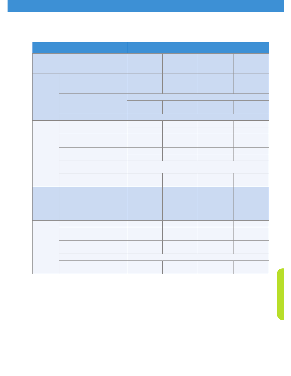
ZX Platform Condensing Unit
38
ZXD Family: Digital Medium Temperature
Technical Data at 60 Hz - TF7
Family ZX
Nominal Rating Horsepower HP 4 5 6 7.5
Model Name
ZXD040E ZXD050E ZXD060E ZXD075E
Performance
R22 ET/AT/RGT °C n/a n/a n/a n/a
Capacity kW
COP W/W
n/a n/a n/a n/a
n/a n/a n/a n/a
R404A/R507A ET/AT/RGT °C
-10/32/18.3
Capacity kW
8.70 10.77 12.54 13.84
COP W/W 2.18 2.11 2.12 2.08
Sound Pressure Level @1m dB(A) 60
Compressor
Model Name R22
R404A/R507A
n/a n/a n/a n/a
ZBD29KQE-TF7 ZBD38KQE-TF7 ZBD45KQE-TF7 ZBD48KQE-TF7
Rated Load Ampere R22 Amp
R404A/R507A Amp
n/a n/a n/a n/a
9.6 11.6 12.9 14.6
Locked Rotor Ampere R22 Amp
R404A/R507A Amp
n/a n/a n/a n/a
54.0 64.0 70.0 78.0
Oil Type R22
R404A/R507A
n/a
POE 3MAF
Oil Recharge Volume R22/R404A Liters
/R507A
1.24 1.77 1.77 1.77
Fan Motor
Number of Fan Pieces 2 2 2 2
Diameter mm 450 450 450 450
Fan Speed rpm 933 933 933 933
Air Flow Total m3/h 6966 6966 6966 6966
Total Fan Motor Power Input W 290 290 290 290
Others
Oil Separator Volume Liters 0.5 0.5 0.5 0.5
Receiver Volume R22 kg
R404A/R507A kg
n/a n/a n/a n/a
6.3 6.3 6.3 6.3
Pipes Suction OD Inch
Liquid OD Inch
7/8 7/8 7/8 7/8
1/2 1/2 1/2 1/2
Dimension W x D x H mm 1029X424X1242
Weight Net kg
Gross kg
109 117 121 127
148 156 158 163
Page 42
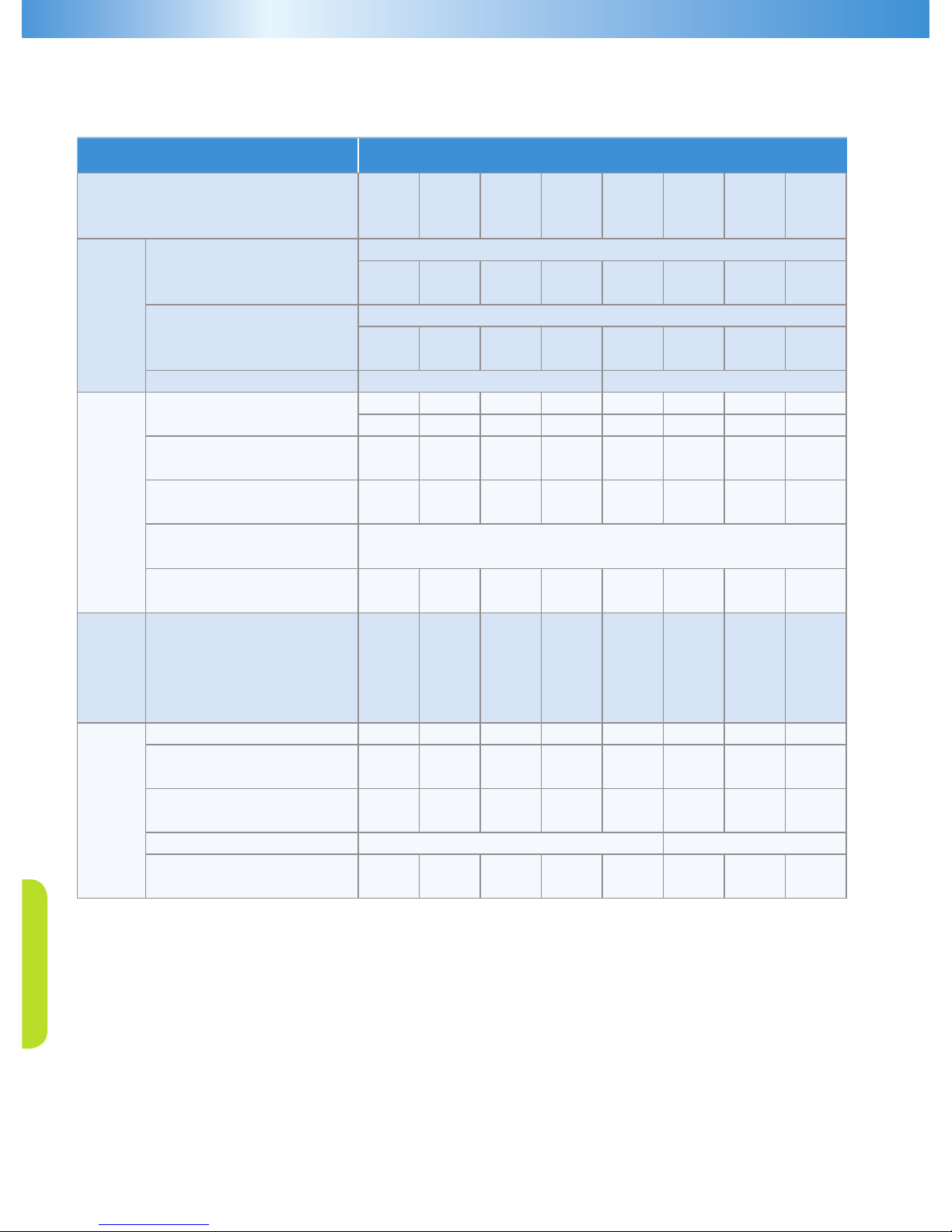
39
ZXL Family: Low Temperature
Technical Data at 50 Hz - TFD
Family ZX
Nominal Rating Horsepower HP 2 2.5 3 3.5 4 5 6 7.5
Model Name
ZXL0200 ZXL0250 ZXL0300 ZXL0350 ZXL0400 ZXL0500 ZXL0600 ZXL0750
ZXL020E ZXL025E ZXL030E ZXL035E ZXL040E ZXL050E ZXL060E ZXL075E
Performance
R22 ET/AT/RGT °C
-32/32/5°C
Capacity kW
1.7 1.91 2.34 2.78 3.57 4.05 4.96 5.39
COP W/W 1.2 1.17 1.28 1.26 1.24 1.29 1.27 1.28
R404A/R507A ET/AT/RGT °C
-32/32/5°C
Capacity kW
2.11 2.51 2.80 3.65 4.26 4.99 5.91 6.65
COP W/W 1.24 1.28 1.29 1.34 1.29 1.36 1.33 1.38
Sound Pressure Level @1m dB(A) 60 61
Compressor
Model Name R22
R404A/R507A
ZXI06KC-TFD ZXI08KC-TFD ZXI09KC-TFD ZXI11KC-TFD ZXI14KC-TFD ZXI15KC-TFD ZXI18KC-TFD ZXI21KC-TFD
ZXI06KCE-TFD ZXI08KCE-TFD ZXI09KCE-TFD ZXI11KCE-TFD ZXI14KCE-TFD ZXI15KCE-TFD ZXI18KCE-TFD ZXI21KCE-TFD
Rated Load Ampere R22 Amp
R404A/R507A Amp
5.4 5.5 5.7 7.4 8.1 8.8 11.1 12.1
5.6 6.2 6.0 8.3 8.6 10.0 11.1 14.6
Locked Rotor Ampere R22 Amp
R404A/R507A Amp
39.2 39.2 39.2 51.5 51.5 51.5 74.0 101.0
39.2 39.2 39.2 51.5 51.5 51.5 74.0 101.0
Oil Type R22
R404A/R507A
MINERAL
POE
Oil Recharge Volume R22/R404A Liters
/R507A
0.56 0.56 0.56 1.24 1.24 1.24 1.77 1.77
Fan Motor
Number of Fan Pieces 1 1 1 1 1 2 2 2
Diameter mm 450 450 450 450 450 450 450 450
Fan Speed rpm 830 830 830 830 830 830 830 830
Air Flow Total m3/h 2922 2922 2922 2922 2922 5910 5910 5910
Total Fan Motor Power Input W 116 116 116 116 116 246 246 246
Others
Oil Separator Volume Liters 0.5 0.5 0.5 0.5 0.5 0.5 0.5 0.5
Receiver Volume R22 kg
R404A/R507A kg
5.1 5.1 5.1 5.1 5.1 7.2 7.2 7.2
4.4 4.4 4.4 4.4 4.4 6.3 6.3 6.3
Pipes Suction OD Inch
Liquid OD Inch
3/4 3/4 3/4 7/8 7/8 7/8 7/8 7/8
1/2 1/2 1/2 1/2 1/2 1/2 1/2 1/2
Dimension W x D x H mm 1029X424X840 1029X424X1242
Weight Net kg
Gross kg
79 81 81 93 93 106 116 121
117 119 119 131 131 150 165 170
Page 43
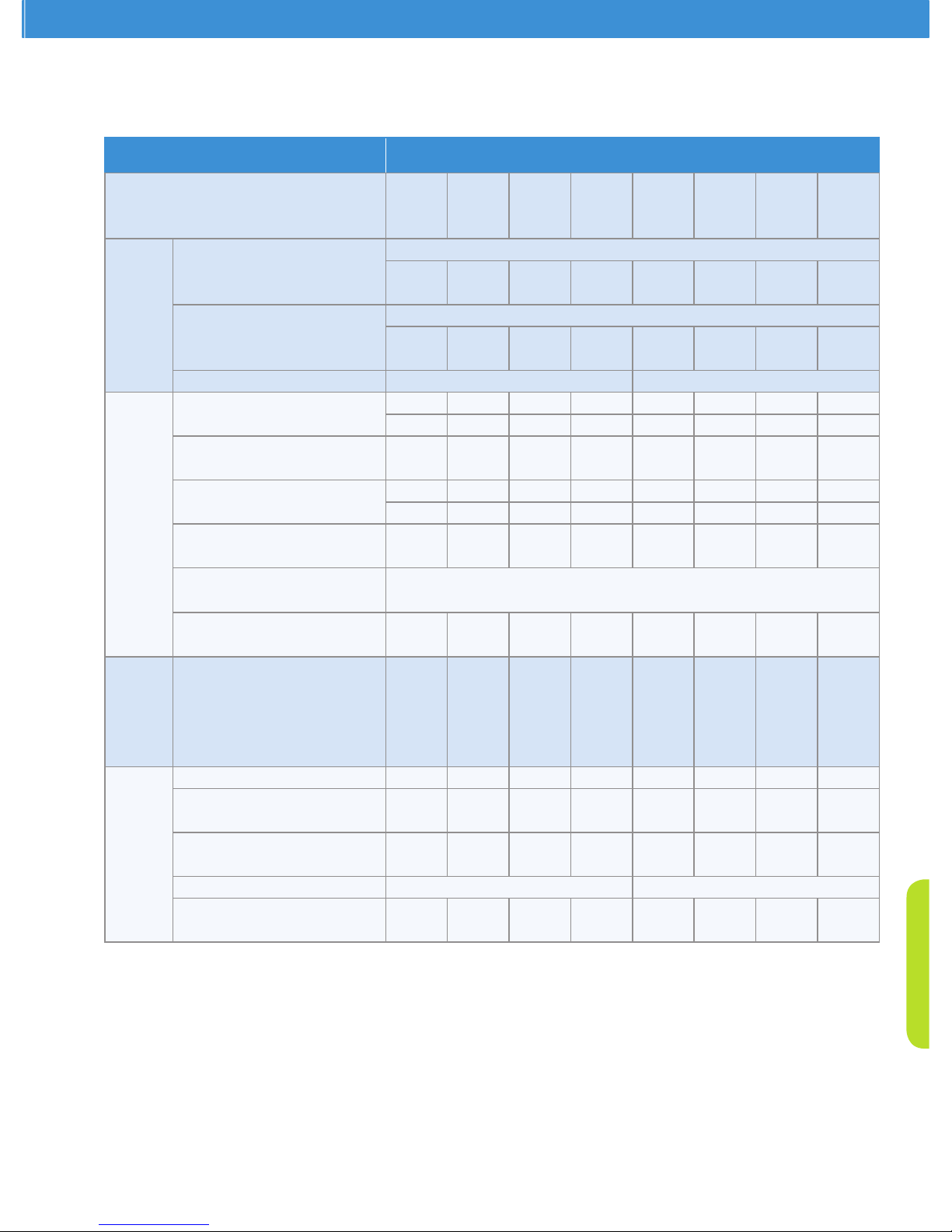
ZX Platform Condensing Unit
40
ZXL Family: Low Temperature
Technical Data at 60 Hz - TF5/TF7
Family ZX
Nominal Rating Horsepower HP 2 2.5 3 3.5 4 5 6 7.5
Model Name
ZXL0200 ZXL0250 ZXL0300 ZXL0350 ZXL0400 ZXL0500 ZXL0600 ZXL0750
ZXL020E ZXL025E ZXL030E ZXL035E ZXL040E ZXL050E ZXL060E ZXL075E
Performance
R22 ET/AT/RGT °C
-32/32/5°C
Capacity kW
2.09 2.69 2.99 2.59 4.72 5.32 6.34 6.81
COP W/W 1.14 1.18 1.28 1.31 1.36 1.37 1.27 1.24
R404A/R507A ET/AT/RGT °C
-32/32/5°C
Capacity kW
2.41 2.83 3.54 4.19 5.18 6.26 7.52 7.98
COP W/W 1.12 1.15 1.32 1.33 1.33 1.44 1.29 1.32
Sound Pressure Level @1m dB(A) 60 61
Compressor
Model Name R22
R404A/R507A
ZXI06KC-TF5/7 ZXI08KC-TF5/7 ZXI09KC-TF5/7 ZXI11KC-TF5/7 ZXI14KC-TF5/7 ZXI15KC-TF5/7 ZXI18KC-TF5/7 ZXI21KC-TF5/7
ZXI06KCE-TF5/7 ZXI08KCE-TF5/7 ZXI09KCE-TF5/7 ZXI11KCE-TF5/7 ZXI14KCE-TF5/7 ZXI15KCE-TF5/7 ZXI18KCE-TF5/7 ZXI21KCE-TF5/7
Rated Load Ampere R22 Amp
TF5 R404A/R507A Amp
12.1 12.6 12.9 19.1 20 21.4 25.5 28.9
12.1 12.6 12.9 19.1 20 21.4 25.5 28.9
Rated Load Ampere R22 Amp
TF7 R404A/R507A Amp
5.4 5.5 6.9 7.7 9.9 12.6 14.1 14.4
5.6 6.2 6.9 8.6 9.9 12.6 14.1 14.4
Locked Rotor Ampere R22 Amp
R404A/R507A Amp
73.0 73.0 73.0 110.0 110.0 110.0 186.6 191.0
34.8 34.8 38.6 47.0 66.0 73.5 94.3 94.3
Oil Type R22
R404A/R507A
MINERAL
POE
Oil Recharge Volume R22/R404A Liters
/R507A
0.56 0.56 0.56 1.24 1.24 1.24 1.77 1.77
Fan Motor
Number of Fan Pieces 1 1 1 1 2 2 2 2
Diameter mm 450 450 450 450 450 450 450 450
Fan Speed rpm 933 933 933 933 933 933 933 933
Air Flow Total m3/h 3483 3483 3483 3483 6966 6966 6966 6966
Total Fan Motor Power Input W 145 145 145 145 290 290 290 290
Others
Oil Separator Volume Liters 0.5 0.5 0.5 0.5 0.5 0.5 0.5 0.5
Receiver Volume R22 kg
R404A/R507A kg
5.1 5.1 5.1 5.1 5.1 5.1 5.1 5.1
4.4 4.4 4.4 4.4 4.4 4.4 4.4 4.4
Pipes Suction OD Inch
Liquid OD Inch
3/4 3/4 3/4 7/8 7/8 7/8 7/8 7/8
1/2 1/2 1/2 1/2 1/2 1/2 1/2 1/2
Dimension W x D x H mm 1029X424X840 1029X424X1242
Weight Net kg
Gross kg
79 81 81 93 93 106 116 121
117 119 119 131 143 150 165 170
Page 44
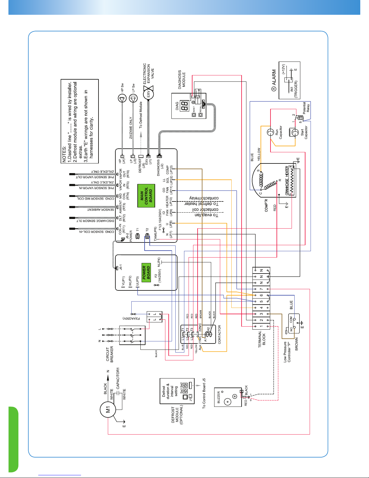
41
BLUE
ZX Condensing Unit Wiring Diagram
PFJ: 220V-50 Hz -1Ph
ATTENTION: Unit MUST be grounded!
Page 45
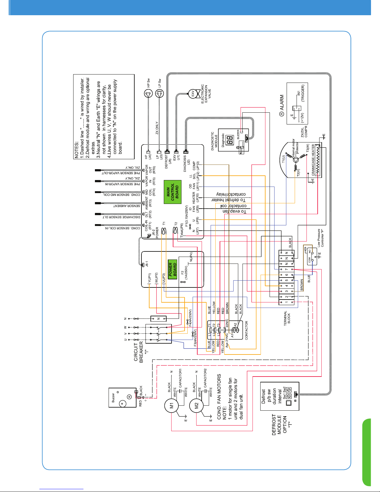
ZX Platform Condensing Unit
42
5.Only ZXL TF5 has 4 additional posts on
the terminal block.
ZX/ZXL Condensing Unit Wiring Diagram
TFD: 380V/420V -50 Hz-3Ph
TF7: 380V-60 Hz -3Ph
ATTENTION: Unit MUST be grounded!
Page 46
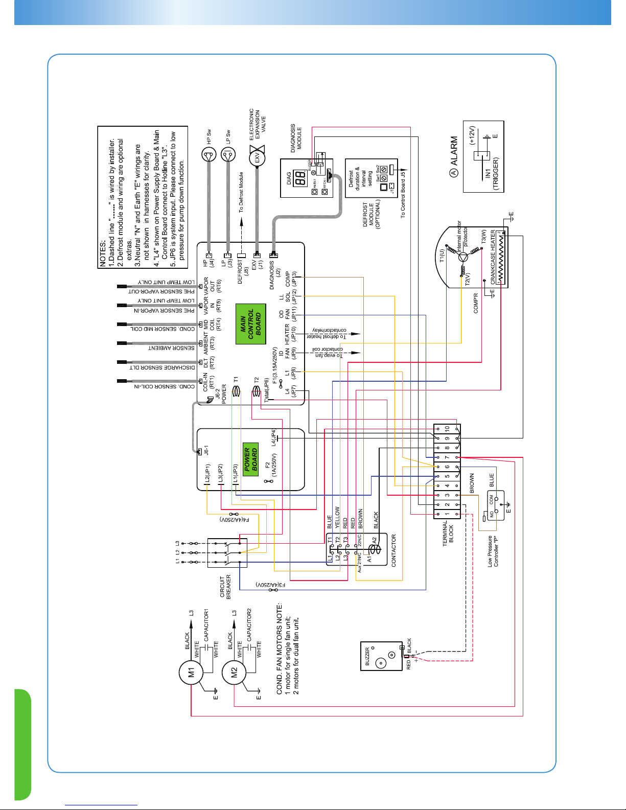
43
ZX/ZXL Condensing Unit Wiring Diagram
TF5: 200/230V- 50 Hz/ 60 Hz - 3Ph
ATTENTION: Unit MUST be grounded!
Page 47
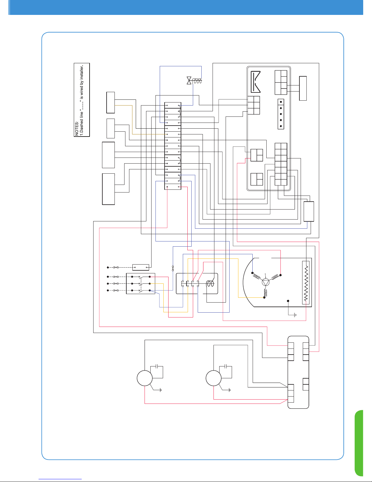
ZX Platform Condensing Unit
44
ZXD Condensing Unit Wiring Diagram (With Fan Speed Control Function)
TFD - 380/420V, 50Hz, 3Ph
TF7 - 380V, 60Hz, 3Ph
052-2662-00
2012-02-15
9 11 N10 NN
Terminal
Block
T1
L1
Aux 21N/C
22N/C
A1
A2
Blue
Blue
Red
Blue
Red
Contactor
Red
T2L2T3
L3
Yellow
Yellow
Circuit
Breaker
"I"
U
VW
135
246
Fuse
(2A/250V)
Transformer
Output:
12VAC
COMP'R
1
2
Crankcase Heater
T1(U)
T2(V)
T3(W)
Internal motor
protector
E
Black
ATTENTION:Unit MUST be grounded!
Notes:
Dashed line " " is wired by installer.
Capacitor1
Black
E
M1
White
White
E
M2
Black
Capacitor2
White
White
Red
Black
N
N
Black
21 22
+ -+ -
23
24
1
2
3
4
5
6
7
8
9
10
11
12
13
14
15
16
17
18
19
20
Compressor DLT
Sensor
COND. Mid
Coil Temp.
Sensor
Pressure
Transducer
HP Switch
25 26
- +
27 28
- +
PWM Valve
LP Switch
Out
0~10V
4~20mA
Hot KeY / TTL
HP i2F
Pb3Pb1Pb2
LP
Id3Id1
1
3
10
12
22
23
24
15 16
12
White
6 87
4
5
1 32
Input:
230VAC
Blue
Blue
Digital Scroll
Controller
Fan Speed Controller
Brown
ZXD Condensing Unit Wiring Diagram
(With Fan Speed Control Function)
TFD: 380V/420V -50 Hz-3Ph
TF7: 380V-60 Hz-3Ph
ATTENTION: Unit MUST be grounded!
Page 48
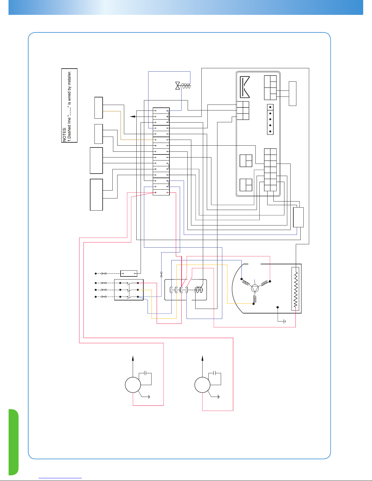
45
ZXD Condensing Unit Wiring Diagram (Without Fan Speed Control Function)
TFD - 380/420V, 50Hz, 3Ph
TF7 - 380V, 60Hz, 3Ph
052-2677-00
2012-03-28
9 11 N10 NN
Terminal
Block
T1
L1
Aux 21N/C
22N/C
A1
A2
Blue
Blue
Red
Blue
Red
Contactor
Red
T2L2T3
L3
Yellow
Yellow
Circuit
Breaker
"I"
U
VW
135
246
Fuse
(2A/250V)
Transformer
Output:
12VAC
COMP'R
1
2
Crankcase Heater
T1(U)
T2(V)
T3(W)
Internal motor
protector
E
Black
ATTENTION:Unit MUST be grounded!
Notes:
Dashed line " " is wired by installer.
Capacitor1
Black
E
M1
White
White
E
M2
Black
Capacitor2
White
White
Red
Black
N
N
Black
21 22
+ -+ -
23
24
1
2
3
4
5
6
7
8
9
10
11
12
13
14
15
16
17
18
19
20
Compressor DLT
Sensor
COND. Mid
Coil Temp.
Sensor
Pressure
Transducer
HP Switch
25 26
- +
27 28
- +
PWM Valve
LP Switch
Out
0~10V
4~20mA
Hot KeY / TTL
HP i2F
Pb3Pb1Pb2
LP
Id3 Id1
12
Brown
6 874
5
1 32
Input:
230VAC
Blue
Blue
To N
To N
To Fan
Red
Red
Digital Scroll
Controller
White
ZXD Condensing Unit Wiring Diagram
(without Fan Speed Control Function)
TFD: 380V/420V-50 Hz-3Ph
TF7: 380V- 60 Hz-3Ph
ATTENTION: Unit MUST be grounded!
Page 49
ZX Platform Condensing Unit
46
Container Loading, ZX Platform Condensing Unit
Family Model Motor Code Fan Type 20FT 40FT/ 40FT H
ZX
ZX0200/E PFJ/TFD/TF5/TF7
Single Fan
40 80
ZX0250/E PFJ 40 80
ZX0300/E PFJ/TFD/TF5/TF7 40 80
ZX0400/E PFJ/TFD 40 80
ZX0400/E TF5/TF7
Dual Fan
20 40
ZX0500/E TFD/TF5/TF7 20 40
ZX0600/E TFD/TF5/TF7 20 40
ZX0750/E TFD/TF5/TF7 20 40
ZXD
ZX0750/E TFD/TF7
Dual Fan
20 40
ZXD0500/E TFD/TF7 20 40
ZXD0600/E TFD/TF7 20 40
ZXD0750/E TFD/TF7 20 40
ZXL
ZXL0200/E TFD/TF5/TF7
Single Fan
40 80
ZXL0250/E TFD/TF5/TF7 40 80
ZXL0300/E TFD/TF5/TF7 40 80
ZXL0350/E TFD/TF5/TF7 40 80
ZXL0400/E TFD 40 80
ZXL0400/E TF5/TF7
Dual Fan
20 40
ZXL0500/E TFD/TF5/TF7 20 40
ZXL0600/E TFD/TF5/TF7 20 40
ZXL0750/E TFD/TF5/TF7 20 40
Packing Information
Conversion Chart
Units Conversion Chart
KCALH x 3.9683 = BTUH
WATTS x 3.413 = BTU/H
1.80 x
O
C + 32 = OF
KILOGRAMS x 2.205 = POUNDS
MILLIMETERS x 0.0394 = INCHES
CUBIC CENTIMETERS x 0.06102 = CUBIC INCHES
CUBIC METERS x 35.3147 = CUBIC FEET
LITERS x 33.8181 = FLUID OUNCES
KILOWATTS x 1.341 = HORSEPOWER
BAR x 14.7 = PSI
Page 50
47
PRESSURE TEMPERATURE CHART AT SEA LEVEL
Red (Bar)=Vacuum Black (Bar)=Vapor Bold (Bar)=Liquid
o
C R12 R22 R-134a
R407A
Vapo r
R407A
Liquid
R404A
HP 62
R407C
Vapo r
R407C
Liquid
R408A R409A R410A R502
R507A
AZ50"
o
F
-45.6 0.53 0.21 0.63 0.30 0.03 0.00 0.37 0.09 0.07 0.63 0.34 -0.03 0.06 -50.0
-44.4 0.49 0.16 0.61 0.26 0.03 0.05 0.33 0.04 0.02 0.61 0.41 0.02 0.12 -48.0
-43.3 0.47 0.12 0.59 0.22 0.08 0.11 0.29 0.01 0.04 0.58 0.48 0.08 0.18 -46.0
-42.2 0.44 0.06 0.56 0.17 0.14 0.17 0.25 0.07 0.10 0.56 0.57 0.14 0.24 -44.0
-41.1 0.41 0.01 0.53 0.12 0.21 0.23 0.20 0.13 0.15 0.53 0.65 0.19 0.30 -42.0
-40.0 0.37 0.04 0.50 0.07 0.27 0.30 0.16 0.19 0.21 0.50 0.74 0.26 0.37 -40.0
-38.9 0.34 0.10 0.47 0.01 0.34 0.37 0.11 0.26 0.28 0.47 0.83 0.32 0.44 -38.0
-37.8 0.30 0.15 0.44 0.04 0.41 0.43 0.06 0.32 0.34 0.44 0.92 0.39 0.52 -36.0
-36.7 0.27 0.21 0.41 0.10 0.48 0.51 0.00 0.39 0.41 0.41 1.01 0.46 0.59 -34.0
-35.6 0.23 0.28 0.37 0.16 0.56 0.59 0.06 0.46 0.48 0.37 1.12 0.53 0.68 -32.0
-34.4 0.19 0.34 0.33 0.23 0.63 0.66 0.11 0.53 0.55 0.34 1.22 0.60 0.75 -30.0
-33.3 0.15 0.41 0.29 0.29 0.72 0.74 0.17 0.61 0.63 0.30 1.33 0.68 0.84 -28.0
-32.2 0.10 0.48 0.25 0.36 0.80 0.83 0.23 0.69 0.71 0.26 1.44 0.76 0.93 -26.0
-31.1 0.06 0.55 0.21 0.43 0.89 0.92 0.30 0.77 0.79 0.22 1.56 0.84 1.02 -24.0
-30.0 0.01 0.63 0.17 0.51 0.98 1.01 0.37 0.86 0.88 0.17 1.68 0.93 1.12 -22.0
-28.9 0.03 0.70 0.13 0.59 1.08 1.10 0.45 0.94 0.97 0.13 1.81 1.01 1.21 -20.0
-27.8 0.09 0.79 0.08 0.67 1.17 1.20 0.52 1.04 1.06 0.08 1.94 1.11 1.32 -18.0
-26.7 0.14 0.87 0.03 0.75 1.28 1.30 0.60 1.14 1.15 0.03 2.07 1.20 1.42 -16.0
-25.6 0.19 0.96 0.02 0.84 1.38 1.41 0.68 1.23 1.25 0.02 2.21 1.30 1.53 -14.0
-24.4 0.25 1.05 0.08 0.93 1.49 1.52 0.77 1.34 1.35 0.07 2.35 1.40 1.64 -12.0
-23.3 0.31 1.14 0.13 1.03 1.60 1.63 0.85 1.44 1.46 0.12 2.50 1.51 1.76 -10.0
-22.2 0.37 1.23 0.19 1.12 1.72 1.74 0.94 1.55 1.57 0.18 2.66 1.61 1.88 -8.0
-21.1 0.43 1.34 0.25 1.23 1.83 1.86 1.03 1.67 1.68 0.24 2.81 1.73 2.00 -6.0
-20.0 0.50 1.44 0.32 1.33 1.96 1.99 1.13 1.79 1.79 0.30 2.98 1.84 2.13 -4.0
-18.9 0.56 1.54 0.38 1.44 2.09
2.12 1.23 1.91 1.91 0.37 3.15 1.96 2.26 -2.0
-17.8 0.63 1.66 0.45 1.55 2.22 2.25 1.34 2.03 2.03 0.43 3.32 2.08 2.40 0.0
-16.7 0.70 1.77 0.52 1.67 2.36 2.39 1.45 2.17 2.16 0.50 3.50 2.21 2.54 2.0
-15.6 0.77 1.89 0.59 1.79 2.50 2.52 1.56 2.30 2.29 0.57 3.69 2.34 2.68 4.0
-14.4 0.85 2.01 0.66 1.92 2.65 2.67 1.68 2.43 2.43 0.65 3.88 2.48 2.83 6.0
-13.3 0.92 2.14 0.74 2.05 2.80 2.82 1.80 2.58 2.57 0.72 4.08 2.61 2.99 8.0
-12.2 1.01 2.26 0.82
2.18 2.95 2.97 1.92 2.72 2.71 0.80 4.29 2.76 3.15 10.0
-11.1 1.09 2.40 0.90 2.32 3.11 3.13 2.05 2.88 2.86 0.88 4.50 2.90 3.31 12.0
-10.0 1.17 2.54 0.99 2.46 3.28 3.30 2.19 3.03 3.01 0.97 4.72 3.06 3.48 14.0
-8.9 1.26 2.68 1.08 2.61 3.45 3.46 2.32 3.19 3.17 1.06 4.94 3.21 3.66 16.0
-7.8 1.35 2.82 1.17 2.76 3.62 3.63 2.46 3.36 3.32 1.14 5.17 3.37 3.83 18.0
-6.7 1.45 2.97 1.27 2.92 3.80 3.81 2.61 3.53 3.49 1.24 5.41 3.53 4.01 20.0
-5.6 1.54 3.12 1.37 3.08 3.99 4.00 2.77 3.71 3.66 1.34 5.65 3.70 4.21 22.0
-4.4 1.64 3.28 1.47 3.25 4.18 4.19 2.92 3.89 3.84 1.43 5.90 3.88 4.40 24.0
-3.3 1.74 3.45 1.58 3.42 4.37 4.38 3.08 4.08 4.02 1.54 6.15 4.06 4.60 26.0
-2.2 1.85 3.61 1.69 3.60 4.57 4.58 3.25 4.27 4.21 1.65 6.42 4.23 4.80 28.0
-1.1 1.96 3.79 1.80 3.78 4.78 4.78 3.42 4.46 4.39 1.76 6.69 4.43 5.01 30.0
0.0 2.07 3.97 1.92 3.97 4.99 4.99 3.59 4.67 4.59 1.87 6.97 4.62 5.23 32.0
1.1 2.18 4.15 2.03 4.17 5.21 5.21 3.78 4.88 4.79 1.99 7.26 4.81 5.45 34.0
2.2 2.30 4.34 2.16 4.37 5.43 5.43 3.97 5.09 5.00 2.10 7.55 5.02 5.68 36.0
3.3 2.42 4.53 2.28 4.57 5.67 5.66 4.16 5.31 5.21 2.23 7.86 5.23 5.91 38.0
4.4 2.54 4.73 2.41 4.79 5.90 5.89 4.36 5.53 5.43 2.36 8.17 5.44 6.15 40.0
5.6 2.67 4.93 2.55 5.00 6.14 6.12 4.56 5.77 5.65 2.49 8.48 5.66 6.39 42.0
6.7 2.80 5.14 2.69 5.23 6.40 6.37 4.77 6.00 5.88 2.62 8.81 5.89 6.65 44.0
7.8 2.94 5.35 2.83 5.46 6.66 6.62 4.99 6.25 6.12 2.77 9.14 6.12 6.90 46.0
8.9 3.08 5.57 2.98 5.70 6.92 6.88 5.21 6.50 6.36 2.90 9.48 6.35 7.17 48.0
Page 51
ZX Platform Condensing Unit
48
PRESSURE TEMPERATURE CHART AT SEA LEVEL
Red (Bar)=Vacuum Black (Bar)=Vapor Bold (Bar)=Liquid
o
C R12 R22 R-134a
R407A
Vapo r
R407A
Liquid
R404A
HP 62
R407C
Vapo r
R407C
Liquid
R408A R409A R410A R502
R507A
AZ50"
o
F
10.0 3.21 5.80 3.13 5.94 7.19 7.14 5.43 6.75 6.60 3.06 9.83 6.59 7.44 50.0
11.1 3.36 6.03 3.29 6.19 7.46 7.41 5.67
7.01
6.86 3.21 10.20 6.84 7.72 52.0
12.2 3.50 6.26 3.45 6.44 7.74 7.70 5.91
7.28
7.11 3.36 10.57 7.10 8.01 54.0
13.3 3.66 6.51 3.61 6.71 8.03 7.98 6.16
7.56
7.38 3.52 10.94 7.35 8.30 56.0
14.4 3.81 6.76 3.79 6.98 8.33 8.27 6.41
7.84
7.65 3.68 11.34 7.62 8.59 58.0
15.6 3.97 7.01 3.96 7.26 8.63 8.57 6.68 8.13 7.93 3.86 11.73 7.89 8.90
60.0
16.7 4.14 7.27 4.14 7.54 8.94 8.88 6.94 8.43 8.21 4.03 12.14 8.17 9.21
62.0
17.8 4.30 7.54 4.32 7.83 9.26 9.19 7.22 8.74 8.50 4.21 12.56 8.46 9.54
64.0
18.9 4.48 7.81 4.51 8.13 9.59 9.50 7.50 9.05 8.80 4.39 12.99 8.74 9.86
66.0
20.0 4.66 8.09 4.70 8.44 9.92 9.83 7.79 9.37 9.10 4.58 13.42 9.04 10.20
68.0
21.1 4.83 8.37 4.90 8.76 10.26 10.17 8.09 9.69 9.42 4.77 13.87 9.34 10.54
70.0
22.2 5.01 8.67 5.11 9.08 10.61 10.51 8.39 10.03 9.74 4.97 14.32 9.66 10.89
72.0
23.3 5.20 8.97 5.32 9.41 10.97 10.86 8.70 10.37 10.06 5.17 14.79 9.98 11.25
74.0
24.4 5.39 9.28 5.53 9.75 11.34 11.22 9.03 10.72 10.40 5.38 15.27 10.30 11.62
76.0
25.6 5.59 9.59 5.75 10.10 11.71 11.59 9.35 11.07 10.74 5.59 15.76 10.63 11.99
78.0
26.7 5.79 9.90 5.98 10.46 12.09 11.96 9.69 11.43 11.09 5.81 16.26 10.97 12.38
80.0
27.8 6.00 10.23 6.21 10.82 12.48 12.34 10.03 11.81 11.44 6.03 16.77 11.32 12.77
82.0
28.9 6.21 10.57 6.45 11.19 12.88 12.73 10.39 12.19 11.81 6.26 17.29 11.67 13.17
84.0
30.0 6.43 10.91 6.69 11.57 13.28 13.13 10.75 12.58 12.18 6.50 17.83 12.03 13.58
86.0
31.1 6.64 11.26 6.94 11.97 13.70 13.54 11.12 12.98 12.56 6.74 18.37 12.40 13.99
88.0
32.2 6.87 11.61 7.19 12.37 14.12 13.96 11.50 13.39 12.94 6.99 18.93 12.78 14.42
90.0
33.3 7.10 11.98 7.46 12.78 14.56 14.39 11.88 13.80 13.34 7.23 19.50 13.16 14.86
92.0
34.4 7.33 12.35 7.72 13.20 15.01 14.82 12.28 14.23 13.74 7.50 20.08 13.55 15.30
94.0
35.6 7.57 12.73 7.99 13.63 15.46 15.26 12.69 14.66 14.16 7.76 20.68 13.95 15.76
96.0
36.7 7.81 13.12 8.28 14.06 15.92
15.72 13.10 15.10 14.58 8.03 21.28 14.36 16.22
98.0
37.8 8.06 13.51 8.57 14.51 16.39 16.18 13.52 15.55 15.01 8.30 21.90 14.78 16.70
100.0
38.9 8.32 13.92 8.86 14.97 16.87 16.66 13.96 16.01 15.45 8.59 22.53 15.20 17.18
102.0
40.0 8.58 14.32 9.15 15.44 17.36 17.14 14.41 16.48 15.90 8.88 23.18 15.63 17.67
104.0
41.1 8.84 14.74 9.46 15.92 17.86 17.63 14.86 16.96 16.35 9.17 23.84 16.08 18.17
106.0
42.2 9.11 15.17 9.77 16.41 18.37 18.13 15.32 17.45 16.82 9.47 24.51 16.52 18.69
108.0
43.3 9.39 15.61 10.10 16.91 18.89 18.65 15.79 17.95 17.29 9.78 25.20 16.99 19.21
110.0
44.4 9.67 16.06 10.42 17.43 19.42 19.17 16.28 18.46 17.78 10.10 25.90 17.45 19.74
112.0
45.6 9.95 16.51 10.76 17.94 19.97 19.70 16.78 18.97 18.27 10.42 26.61 17.93 20.29
114.0
46.7 10.25 16.97 11.10 18.48 20.52 20.25 17.28 19.50 18.77 10.74 27.34 18.41 20.85
116.0
47.8 10.54 17.45 11.45 19.03 21.08 20.81 17.80 20.04 19.29 11.08 28.09 18.91 21.41
118.0
48.9 10.85 17.93 11.81 19.59 21.66 21.37 18.33 20.59 19.81 11.43 28.85 19.41 21.99
120.0
50.0 11.16 18.42 12.17 20.16 22.23 21.95 18.87 21.15 20.34 11.78 29.62 19.92 22.59
122.0
51.1 11.47 18.92 12.54 20.74 22.83 22.54 19.42 21.72 20.89 12.14 30.41 20.45 23.19
124.0
52.2 11.79 19.43 12.92 21.33 23.44 23.14 19.99 22.30 21.44 12.50 31.22 20.99 23.80
126.0
53.3 12.12 19.94 13.31 21.94 24.06 23.75 20.56 22.90 22.01 12.88 32.04 21.52 24.43
128.0
54.4 12.45 20.48 13.70 22.56 24.68 24.38 21.14 23.50 22.58 13.26 32.88 22.08 25.07
130.0
55.6 12.79 21.01 14.11 23.19 25.32 25.02 21.75 24.12 23.17 13.64 33.74 22.65 25.72
132.0
56.7 13.14 21.56 14.52 23.84 25.98 25.67 22.36 24.74 23.77 14.04 34.61 23.22 26.39
134.0
57.8 13.49 22.12 14.94 24.50 26.64 26.34 22.99 25.38 24.37 14.44 35.50 23.81 27.06
136.0
58.9 13.85 22.69 15.37 25.18 27.32 27.01 23.63 26.03 24.99 14.86 36.41 24.40 27.75
138.0
60.0 14.21 23.27 15.81 25.87 28.01 27.70 24.28 26.69 25.62 15.28 37.34 25.01 28.46
140.0
61.1 14.58 23.86 16.26 26.57 28.71 28.41 24.94 27.36 26.27 15.70 38.29 25.62 29.18
142.0
62.2 14.96 24.46 16.71 27.29 29.43 29.13 25.63 28.04 26.92 16.14 39.26 26.26 29.92
144.0
63.3 15.34 25.07 17.17 28.02 30.15 29.87 26.32 28.74 27.59 16.59 40.24 26.90 30.67
146.0
64.4 15.73 25.69 17.65 28.77 30.90 30.61 27.03 29.45 28.27 17.05 41.25 27.54 31.43
148.0
65.6 16.13 26.32 18.13 29.54 31.65 31.39 27.76 30.17 28.96 17.51 42.28 28.21 32.22
150.0
Page 52

Asia 02 A0104 – R00 Issued 5/2012
Emerson, Copeland PerformanceAlert and Copeland Scroll are trademarks of Emerson Electric Co. or one of its afliated companies.
©2012 Emerson Climate Technologies, Inc. All rights reserved.
EmersonClimate.com/Asia
Contact Lists
Emerson Climate Technologies
Asia Pacific Headquarters
10/F, Pioneer Building,
213 Wai Yip Street,
Kwun Tong, Kowloon, Hong Kong
Tel: (852) 2866 3108
Fax: (852) 2520 6227
India - PUNE
Emerson Climate Technologies Ltd
India Head Office
Plot No. 23, Rajiv Gandhi Infotech Park,
Phase - II, Hinjewadi,
Pune 411 057, Maharashtra, India
Tel: (91-20) 2553 4988
Fax: (91-20) 2553 6350
Indonesia
PT Emerson Indonesia
Wisma 46 - Kota BNI, 16th Floor, Suite 16.01 ,
Jl. Jend.Sudirman Kav.1.
Jakarta 10220
INDONESIA
Tel: (62)21-2513003 ext.6000
Fax: (62)21-2510622
Japan
Emerson Japan Ltd
Shin-yokohama Tosho Building No. 3
3-9-5 Shin-Yokohama, Kohoku-ku
Yokohama 222-0033 Japan
Tel: (81-45)475 6371
Fax: (81-45)475 3565
Korea
Emerson Electric Korea Ltd
3F Pharos Tower, 119 Nonhyeon-dong
Gangnam-gu, Seoul, Korea 135-010
Tel: (82-2) 3483-1500
Fax: (82-2) 592-7883 / 592-7886
Malaysia
Emerson Electric (Malaysia) Sdn. Bhd.
Level M2, Blk A, Menara PKNS-PJ
Jalan Yong Shook Lin
46050 Petaling Jaya, Selangor, Malaysia
Tel: (60-3) 7949 9222
Fax: (60-3) 7949 9333
Middle East & Africa
Emerson Climate Technologies
PO Box 26382
Jebel Ali Free Zone – South
Dubai, UAE
Tel: (971- 4) 811 8100
Fax: (971- 4) 886 5465
Philippines
Emerson Climate Technologies
23rd Floor San Miguel Properties Centre
#7 St. Francis Street, Ortigas Center,
Mandaluyong City, Philippines
Tel: (63) 479 3824
Taiwan
Emerson Electric (Taiwan) Co. Ltd
3rd Floor, Dunhua South Road
Section 1, Taipei 10650, Taiwan, R.O.C.
Tel: (+886-2) 8161 7688
Fax: (+886-2) 2702 9630
Thailand - Bangkok
Emerson Electric (Thailand) Ltd
34th Floor Nation Tower
1858/133 Bangna Trad
Bangkok 10260 , Thailand
Tel: (66-2) 716 4700
Fax: (66-2) 751 4240
Vietnam
Emerson Climate Technologies - Vietnam
Suite 307-308,
123 Truong Dinh St., Dist.3 Ho Chi Minh,
Vietnam
Tel: 84 908 009 189
Australia
Emerson Climate Technologies Australia
Pty Ltd
Unit R7, 391 Park Road
Regents Park, NSW 2143, Australia
Tel: (61-2) 9795 2800
Fax: (61-2) 9738 1699
China - Beijing
Emerson Climate Technologies (Suzhou)
Co. Ltd
Beijing Sales Office
Room 1017, Canway Building
66 Nan Lishi Road, Xicheng District
Beijing 100045, China
Tel: (86-10) 5763 0488
Fax: (86-10) 5763 0499
China - Guangzhou
Emerson Climate Technologies (Suzhou)
Co. Ltd
Guangzhou Sales Office
Room 508-509, R&F Yinglong Plaza
No. 76 Huangpu Road West,
Guangzhou 510623, PRC.
Tel: (86-20) 2886 7668
Fax: (86-20) 2886 7622
China - Shanghai
Emerson Climate Technologies (Suzhou)
Co. Ltd
Shanghai Sales Office
Room 1801, Building B,
New Caohejing International Business Center,
Shanghai 200233, China
Tel: (86-21) 34183999
Fax: (86-21) 34183988
 Loading...