


Copeland Scroll
TM
ZB digital compressor

About Emerson Climate Technologies
Emerson Climate Technologies, a business segment of Emerson, is the world’s leading provider of heating, airconditioning and refrigeration solutions for residential, industrial and commercial applications. It combines best-in-class
technology with proven engineering, design, distribution, educational and monitoring services to provide customized,
integrated climate-control solutions for customers worldwide. Climate’s innovative solutions, which include industryleading brands such as Copeland ScrollTM, improve human comfort, safeguard food and protect the environment. For
more information, visit EmersonClimateAsia.com.
Emerson Climate Technologies, With Our Partners,
Will Provide Global Solutions To Improve Human Comfort,
Safeguard Food And Protect The Environment.
Our Vision:

Index
Introduction 01
Digital Scroll Advantage for Rack Systems 02
Intelligent Store
TM
03
Nomenclature 04
Bill of Material 04
ZBD Rack Specication 05
Operating Envelope 06
Performance Table 07
Technical Data 13
Dimensional Drawings 14
Flow Controls Parts 21
OMB Crankcase Oil Level Protective Control 21
A-W/A-F Oil Separators 22
AOFD-553 Oil Filter Drier 24
STAS Steel Liquid and Suction Line Filter Drier 25
ADKS Liquid And Suction Line Filter Drier 26
Filter-Drier Cores And Filters 28
HMI-Hermetic Moisture Indicators 29
PS1 Single Pressure Controls 31
APD Pulsation Dampener/Mufer 33
Scroll Rack Application Guidelines 34
Digital Compressor Rack Controller-XC645CX 40
Contact List 49

1
Leading Innovations in Digital Scroll Technology
Emerson Climate Technologies has revolutionized the industry with the introduction of its scroll technology, which was launched in 1987.
In 2012, Emerson produced its 100 millionth scroll - a signicant achievement and further demonstrating Emerson’s position as a world
leader in the development and application of scroll technology.
Energy-efcient Refrigeration Through Capacity Modulation
Today, Emerson is the world’s largest manufacturer of refrigeration compressors, underscoring Emerson Climate Technologies’ thrust of
ensuring food safety and protecting the environment. Leveraging on Emerson’s vast global network and R&D resources, the company also
continues to develop the ultimate in climate technology for various businesses. Emerson helps provide solutions to achieve high efciency
systems for cold storage warehouses, supermarkets, quick service restaurants, meat trading and processing facilities, seafood import and
export establishments, agricultural depots and retail outlets - green technologies with less environmental impact.
With today’s growing need to address energy efciency and precise temperature control, Emerson developed ZBD compressors – digital
scroll technology in a simplied, compact design that is very reliable.
The ZBD features continuous capacity modulation range of 10-100%. This eliminates hot gas bypass, which causes waste of electricity,
and complications arising from variable speed drives. Precise capacity modulation control proves benecial in a number of applications,
including precise temperature control for precision cooling and humidity control as well as parallel compressor operations or rack systems
– intermediate and more precise part load operation of a compressor to perfectly match varying evaporator loads. Compared to cycling
compressors, smoother and more precise load matching is enabled by stepless capacity control with the ZBD.
Key Features and Benets
• Digital Scroll technology provides higher efciency compared to hot gas bypass systems or
compressor cycling
• Less complicated compared to variable speed technologies
• More reliable compared to other modulation technologies due to elimination of oil return issues
• Suitable for rack systems due to its varying load requirements
• Proven scroll technology paired with mechanical unloading system provides greater
reliability and efciency

2
Digital Scroll Advantage for Rack Systems
Digital scroll compressors having modulation capabilities from 10%–100% naturally t refrigeration rack systems. Rack systems need to
fulll varying evaporator load requirements due to changing case loads, not to mention variations due to cases undergoing routine defrost.
This can be attained by complementing xed-speed compressor racks with a digital scroll of the same capacity. The refrigeration load will
be matched by running xed-speed compressors to handle the base load and the peaks by the digital scroll. This leads to a smooth and
almost constant system suction pressure (see charts below). Compared to xed-speed scroll racks where unloading is achieved by cycling
the lead compressor, this results in a saw tooth prole of the system suction pressure and will reduce the life of the lead compressor due to
frequent on and off action. Fluctuating suction pressures lead to varying evaporator temperature and humidity conditions—a condition
that is not advisable for refrigerated products.
Compressor modulation by cycling compressor on and off
Saw tooth prole of suction pressure for
xed speed compressor
Compressor modulation by digital scroll
Smooth system suction pressure
Suction Pressure
Time
Suction Pressure
Time
3
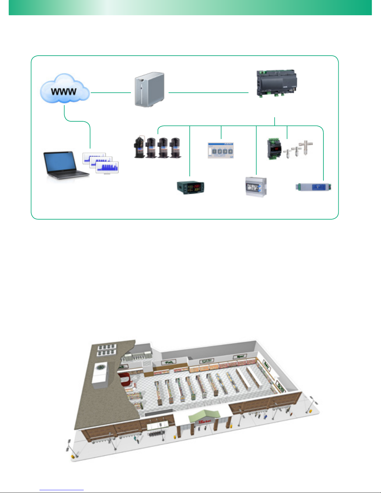
An innovative approach to enterprise facility management, Emerson’s Intelligent Store architecture integrates hardware and services
to help hyper mart, supermarket, convenience store, and box retail operators make better facility decisions while reducing operational
costs. The Intelligent Store architecture implements best practices for facility management and transforms data from store equipment
and controls into actionable insights. Designed to deliver value in both new and existing stores, the Intelligent Store architecture can help
retailers signicantly improve their bottom line results. The Intelligent Store solution constitutes:
• Energy efcient store infrastructure components
• State-of-the-art control technologies: XWeb Supervisory Platform
• Field services: Commissioning and project management
• Remote services: Alarm Management, Setpoint Management, Demand Response, Condition Based Maintenance, Energy Monitoring
and Targeting, Smart Dispatch, Food Quality Reports and Site Administration
Rack with
ZB Digital Scroll
Digital Compressor
Rack Controller
Power Meters
Dewpoint
Controller
Lighting and
HVAC Control
Superheat Controller
and EEV
ProAct Services
Intelligent Store
TM
XWeb Supervisory
Platform
4
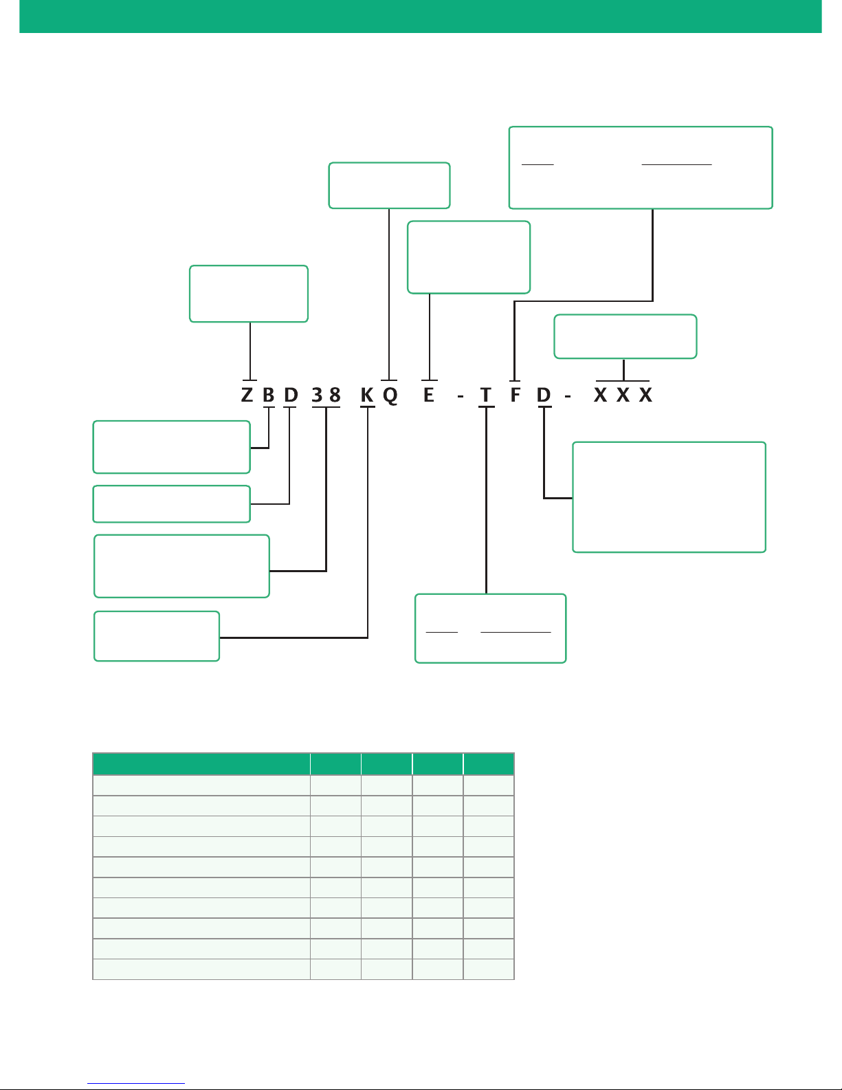
Nomenclature
Generation
Compressor
Family
High/Medium Temp
Refrigeration
Capacity at 60Hz
(Medium Temperature
Condition: Btu/h)
Base Capacity
K x 1000
Bill of Material
Lubricant
Blank: Mineral Oil
E: Ester Oil
Compressor Motor
Code Description
T: Three-phase
Motor Voltages
D
5
7
Compressor Motor Protection
Code Description
F: Inherent internal line break
motor protector
Digital Modulation
50 Hz 60Hz
380/420-3
200/220-3
460-3
200/230-3
380-3
Bill of Material
BOM 558 559 588 589
Sight Glass
✓ ✓ ✓ ✓
Stub Tube
✓
Rotalock
✓ ✓
Digital Valve
✓ ✓
Solenoid Coil
✓ ✓
Digital Rack Controller Kit
✓ ✓
Discharge Line Temperature Sensor
✓ ✓
Condenser Mid Coil Temperature Sensor
✓ ✓
OMB
✓ ✓
OMB Adaptor
✓ ✓

5
Family Items Unit
ZBD Rack Package ZBD Rack Recommendation
STD BOM 10HP 15HP
Compressor
Digital Scroll Compressor EA
✓
ZBD38KQ ZBD38KQ
Standard Scroll Compressor EA
- ZB38KQ ZB38KQ
- - ZB38KQ
Digital
Accessory
Thermistor
1
EA
✓
043-0130-00 043-0130-00
Valve Body EA
✓
010-0125-00 010-0125-00
Solenoid Coil
2
EA
✓
023-0088-00 023-0088-00
Rack Control
Kit
Controller (XC645CX) EA
✓
085-0254-00 085-0254-00
4-20mA Suction Pressure Transducer EA
✓
085-0233-00 085-0233-00
Condenser Mid Coil Temperature
Sensor
EA
✓
043-0168-02 043-0168-02
4-20mA Condenser Pressure
Transducer
3
EA - Optional Optional
TTL / RS485 Serial Converter
3
EA
✓
029-0502-00 029-0502-00
Hot Key EA - 085-0234-00 085-0234-00
Transformer EA
✓
037-0025-00 037-0025-00
Wiring Kit 3m
✓
029-0501-00 029-0501-00
Digital Input and Analog Out
Connector
3m
✓
029-0472-01 029-0472-01
System
Protector
Oil Regulator, OMB-JB1 ASC 2 24/50 EA
✓
085-0245-00 085-0245-00
Adapter for ZBD Sight Glass EA
✓
034-0236-00 034-0236-00
HP EA - PS1-A5A PS1-A5A
LP EA - PS1-A3A PS1-A3A
Oil Separator EA - A-W55877 A-W55889
Oil Filter Drier EA - AOFD553 AOFD553
Filter Drier EA - Shell STAS-487T Shell STAS-489T
EA - Core H-48 Core H-48
Sight Glass EA - HMI HMI
Pulsation Damper EA - APD APD
ZBD Rack Specication
Solenoid Coil Part Code
Part Code Description
023-0088-00 220V 50/60Hz
023-0088-04 240V 50/60Hz
023-0088-05 200V 50/60Hz
023-0088-07 24V 50/60Hz
Notes: 1. Thermistor: Only for ZBD29KQ, PCN 043-0130-00
2. Solenoid coil part code
3. Please contact Emerson sales representative if the part is required

6
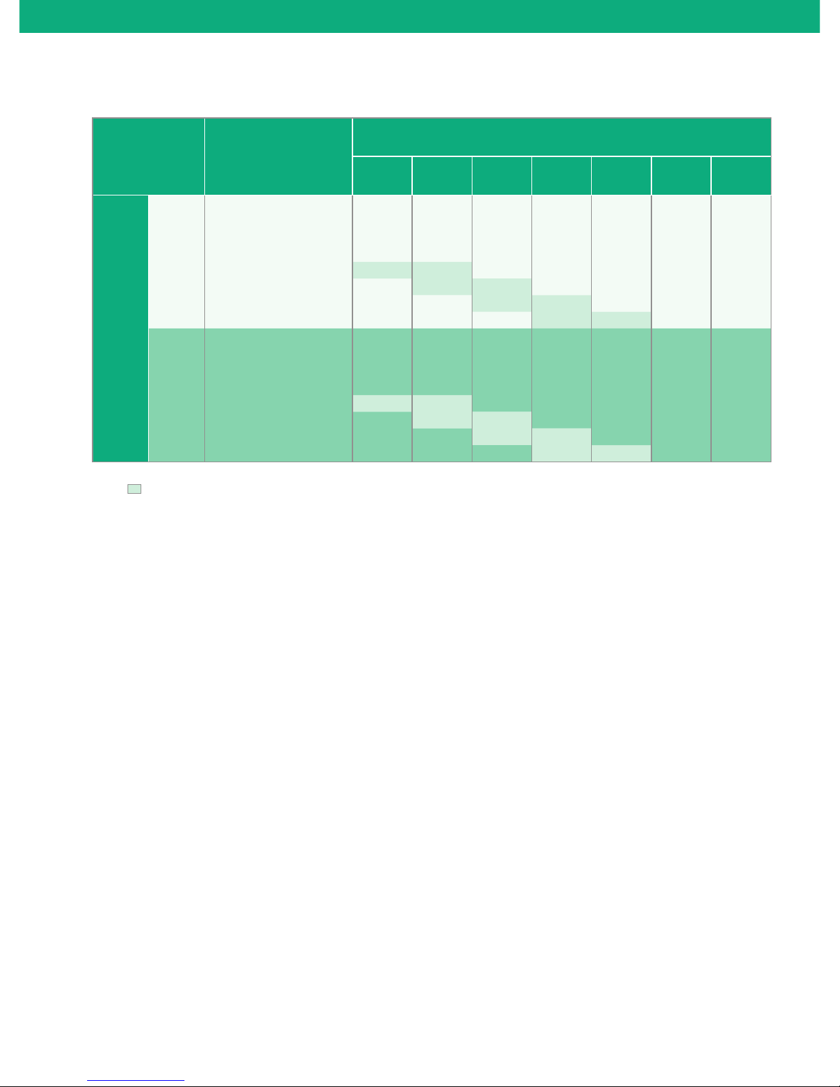
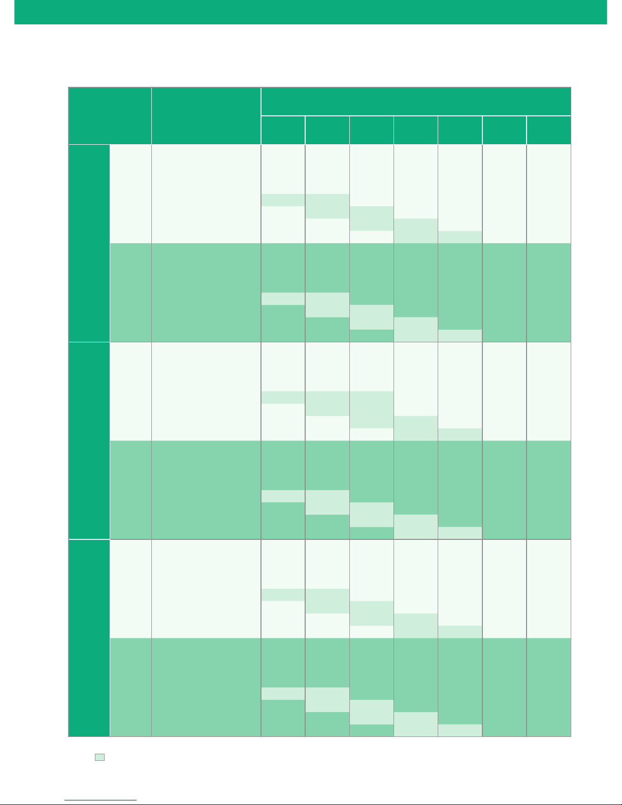
Operating Envelope
ZBD29 - ZBD48
ZBD29 - ZBD48
60
70
50
40
30
20
10
-20 -15 -10 -5 0 5 10
Evaporating Temp. oC
Condensing Temp.
o
C
60
70
50
40
30
20
10
-15-10 -5 0510 15
Evaporating Temp. oC
Condensing Temp.
o
C
1. En
velope in unshaded region, max return gas temperature of 18.3°C
2. En
velope in shaded region, max superheat of 11K only
1. Envelope in unshaded region, max return gas temperature of 18.3oC
Notes:
Note:
R22
ZBD29 - ZBD48
60
70
50
40
30
20
10
-20 -15 -10 -5 0 5 10
Evaporating Temp. oC
Condensing Temp.
o
C
1. Envelope in unshaded region, max return gas temperature of 18.3oC
Note:
R404A

7
Performance Table
Q=Capacity (kW) P=Power input (kW) 3-Phase
R22 50 Hz
Compressor
Condensing
Temperature
o
C
Evaporating Temperature (oC)
-12 -10 -5 0 5 10 12.5
ZBD29KQ
Q
15
7.90 8.53 10.30 12.40
20 7.58 8.19 9.89 11.90 14.20
30 6.99 7.55 9.11 10.90 13.00 15.45 16.75
40 6.37 6.89 8.32 9.98 11.90 14.10 15.30
50 5.60 6.09 7.45 8.96 10.70 12.70 13.80
55 5.62 6.91 8.41 10.05 11.95 13.00
60 6.34 7.75 9.38 11.20 12.20
65 7.07 8.62 10.35 11.30
P
15 1.46 1.48 1.52 1.57
20 1.62 1.64 1.68 1.74 1.80
30 1.98 2.01 2.06 2.11 2.17 2.24 2.28
40 2.44 2.46 2.52 2.57 2.62 2.67 2.69
50 3.05 3.08 3.14 3.18 3.21 3.24 3.25
55 3.46 3.52 3.56 3.58 3.60 3.60
60 3.96 3.99 4.01 4.01 4.00
65 4.49 4.50 4.49 4.47
ZBD38KQ
Q
15 8.72 9.20 10.60 12.30
20 9.12 9.69 11.30 13.25 15.50
30 8.86 9.55 11.45 13.60 16.10 18.95 20.50
40 7.95 8.64 10.50 12.70 15.15 17.95 19.50
50 7.20 7.79 9.48 11.35 13.50 16.00 17.40
55 7.71 9.12 10.80 12.75 14.95 16.20
60 9.10 10.45 12.15 14.05 15.15
65 10.50 11.80 13.35 14.25
P
15 2.24 2.35 2.65 3.00
20 2.21 2.28 2.48 2.70 2.97
30 2.55 2.58 2.65 2.72 2.81 2.92 2.99
40 3.14 3.17 3.23 3.27 3.29 3.32 3.34
50 3.65 3.73 3.90 4.01 4.09 4.15 4.17
55 3.90 4.16 4.36 4.51 4.62 4.67
60 4.32 4.63 4.88 5.08 5.16
65 4.79 5.17 5.48 5.62
ZBD45KQ
Q
15 10.25 10.85 12.50 14.50
20 10.75 11.45 13.35 15.60 18.30
30 10.50 11.30 13.55 16.10 19.00 22.40 24.20
40 9.48 10.30 12.50 15.05 17.95 21.30 23.10
50 8.70 9.40 11.40 13.60 16.15 19.10 20.70
55 9.35 11.00 13.00 15.30 17.90 19.40
60 11.05 12.65 14.65 16.90 18.20
65 12.80 14.30 16.15 17.20
P
15 2.63 2.76 3.12 3.52
20 2.61 2.70 2.93 3.19 3.50
30 3.02 3.06 3.15 3.23 3.34 3.48 3.57
40 3.73 3.77 3.85 3.90 3.94 3.98 4.00
50 4.36 4.46 4.66 4.80 4.91 4.98 5.01
55 4.68 4.99 5.23 5.42 5.56 5.62
60 5.20 5.57 5.88 6.12 6.22
65
5.79 6.24
6.62 6.79
Notes: Suction Return Temperature 18.3oC
Suction Superheat 11.0K
Liquid subcooling 0.0K
8
Performance Table
Q=Capacity (kW) P=Power input (kW) 3-Phase
R22 50 Hz
Compressor
Condensing
Temperature
o
C
Evaporating Temperature (oC)
-12 -10 -5 0 5 10 12.5
ZBD48KQ
Q
15
11.55 12.20 14.05 16.30
20 12.10 12.85 15.05 17.60 20.60
30 11.80 12.75 15.25 18.15 21.40 25.20 27.30
40 10.65 11.60 14.10 17.00 20.30 24.00 26.00
50 9.79 10.60 12.85 15.35 18.25 21.60 23.40
55 - 10.55 12.45 14.70 17.30 20.30 22.00
60 - - 12.50 14.35 16.60 19.15 20.60
65 - - - 14.45 16.20 18.30 19.50
P
15 2.96 3.11 3.51 3.97
20 2.92 3.01 3.28 3.58 3.93 - -
30 3.35 3.39 3.49 3.59 3.71 3.86 3.96
40 4.11 4.16 4.24 4.29 4.33 4.37 4.40
50 4.76 4.87 5.10 5.25 5.37 5.45 5.48
55 5.07 5.43 5.70 5.90 6.06 6.13
60 5.62 6.04 6.38 6.65 6.77
65
6.23 6.74
7.17 7.35
Notes: Suction Return Temperature 18.3oC
Suction Superheat 11.0K
Liquid subcooling 0.0K

9
Performance Table
Q=Capacity (kW) P=Power input (kW) 3-Phase
R404A 50 Hz
Compressor
Condensing
Temperature
o
C
Evaporating Temperature (oC)
-20 -15 -10 -5 0 5 10
ZBD29KQE
Q
10 7.13 8.67 10.45
20 6.49 7.90 9.54 11.45 13.65
30 5.80 7.06 8.53 10.20 12.15 14.40 17.00
40 5.04 6.14 7.40 8.86 10.55 12.50 14.75
50 4.21 5.11 6.15 7.36 8.76 10.40 12.30
60 3.97 4.77 5.70 6.80 8.10 9.62
P
10 1.39 1.36 1.35
20 1.83 1.85 1.86 1.87 1.91
30 2.19 2.25 2.29 2.32 2.35 2.42 2.52
40 2.63 2.72 2.78 2.82 2.86 2.91 2.98
50 3.28 3.41 3.50 3.55 3.58 3.61 3.66
60 4.47 4.57 4.63 4.66 4.67 4.69
ZBD38KQE
Q
10 9.18 11.00 13.10
20 8.14 9.82 11.85 14.15 16.75
30 7.19 8.75 10.55 12.65 15.05 17.70 20.80
40 6.28 7.64 9.23 11.05 13.15 15.50 18.20
50 5.33 6.46 7.77 9.29 11.05 13.05 15.30
60 6.15 6.14 7.30 8.66 10.25 12.05
P
10 1.84 1.88 1.90
20 2.37 2.46 2.53 2.58 2.60
30 2.85 2.97 3.09 3.18 3.25 3.30 3.31
40 3.37 3.52 3.67 3.79 3.90 3.99 4.05
50 4.01 4.18 4.35 4.50 4.64 4.75 4.84
60 5.03 5.21 5.38 5.53 5.67 5.79
ZBD45KQE
Q
10 10.90 13.05 15.60
20 9.69 11.70 14.05 16.80 19.90
30 8.56 10.40 12.55 15.05 17.85 21.10 24.70
40 7.47 9.09 10.95 13.15 15.65 18.45 21.60
50 6.35 7.69 9.24 11.05 13.15 15.50 18.20
60 6.12 7.30 8.68 10.30 12.15 14.30
P
10 2.20 2.25 2.27
20 2.82 2.93 3.01 3.07 3.10
30 3.40 3.55 3.68 3.79 3.88 3.93 3.95
40 4.02 4.20 4.37 4.52 4.65 4.76 4.82
50 4.78 4.99 5.18 5.37 5.53 5.67 5.78
60 6.01 6.22 6.42 6.61 6.77 6.91
ZBD48KQE
Q
10 12.30 14.70 17.50
20 10.90 13.15 15.85 18.90 22.40
30 9.63 11.70 14.15 16.90 20.10 23.70 27.80
40 8.40 10.25 12.35 14.80 17.60 20.80 24.30
50 7.14 8.65 10.40 12.45 14.75 17.45 20.50
60 6.89 8.21 9.77 11.60 13.70 16.10
P
10 2.42 2.47 2.50
20 3.10 3.22 3.31 3.38 3.41
30 3.73 3.90 4.04 4.17 4.26 4.32 4.34
40 4.41 4.61 4.80 4.97 5.11 5.23 5.30
50 5.25 5.48 5.69 5.89 6.07 6.23 6.35
60 6.60 6.83
7.05 7.25
7.43 7.58
Notes: Suction Return Temperature 18.3oC
Liquid subcooling 0.0K
10
Performance Table
Q=Capacity (kW) P=Power input (kW) 3-Phase
R22 60 Hz
Compressor
Condensing
Temperature
o
C
Evaporating Temperature (oC)
-12 -10 -5 0 5 10 12.5
ZBD29KQ
Q
15 9.49 10.25 12.35 14.85
20 9.11 9.84 11.90 14.25 17.00
30 8.40 9.07 10.95 13.10 15.60 18.50 20.10
40 7.66 8.27 9.98 11.95 14.25 16.90 18.35
50 6.75 7.32 8.94 10.75 12.80 15.20 16.55
55 6.79 8.30 10.10 12.05 14.35 15.60
60 7.65 9.31 11.25 13.40 14.60
65 8.52 10.35 12.45 13.55
P
15 1.76 1.77 1.82 1.89
20 1.95 1.97 2.02 2.09 2.17
30 2.38 2.41 2.47 2.54 2.61 2.69 2.74
40 2.93 2.96 3.03 3.09 3.15 3.21 3.24
50 3.67 3.70 3.77 3.82 3.86 3.90 3.91
55 4.16 4.23 4.28 4.31 4.33 4.33
60 4.76 4.80 4.82 4.82 4.82
65 5.40 5.41 5.40 5.38
ZBD38KQ
Q
15 10.45 11.05 12.70 14.75
20 10.95 11.65 13.60 15.90 18.65
30 10.65 11.45 13.75 16.35 19.35 22.80 24.70
40 9.56 10.40 12.65 15.25 18.20 21.60 23.40
50 8.67 9.39 11.40 13.70 16.30 19.30 21.00
55 9.29 11.00 13.05 15.40 18.10 19.60
60 11.00 12.65 14.65 17.00 18.30
65 12.70 14.25 16.15 17.25
P
15 2.68 2.81 3.17 3.58
20 2.65 2.74 2.97 3.24 3.55
30 3.06 3.09 3.18 3.27 3.38 3.52 3.60
40 3.76 3.80 3.88 3.93 3.96 4.00 4.02
50 4.38 4.48 4.68 4.82 4.92 5.00 5.03
55 4.68 5.00 5.24 5.42 5.57 5.62
60 5.20 5.57 5.87 6.12 6.22
65 5.77 6.22 6.61 6.77
ZBD45KQ
Q
15 12.45 13.10 15.10 17.55
20 13.00 13.85 16.15 18.90 22.10
30 12.65 13.65 16.35 19.45 23.00 27.10 29.30
40 11.40 12.40 15.10 18.15 21.70 25.70 27.90
50 10.40 11.25 13.65 16.35 19.45 23.00 25.00
55 11.15 13.20 15.65 18.40 21.60 23.40
60 13.20 15.20 17.60 20.30 21.90
65 15.30 17.15 19.40 20.70
P
15 3.17 3.33 3.75 4.23
20 3.15 3.25 3.53 3.84 4.22
30 3.64 3.69 3.79 3.90 4.03 4.20 4.30
40 4.49 4.54 4.63 4.69 4.74 4.79 4.82
50 5.23 5.35 5.59 5.77 5.89 5.99 6.03
55 5.61 5.98 6.28 6.50 6.67 6.75
60 6.23 6.68 7.05 7.34 7.47
65
6.94 7.48
7.94 8.14
Notes: Suction Return Temperature 18.3oC
Suction Superheat 11.0K
Liquid subcooling 0.0K

11
Performance Table
Q=Capacity (kW) P=Power input (kW) 3-Phase
R22 60 Hz
Compressor
Condensing
Temperature
o
C
Evaporating Temperature (oC)
-12 -10 -5 0 5 10 12.5
ZBD48KQ
Q
15 13.85 14.60 16.85
19.55
20 14.45 15.40 17.95 21.00 24.60
30 14.05 15.15 18.15 21.60 25.60 30.10 32.60
40 12.55 13.65 16.70 20.10 24.00 28.50 31.00
50 11.30 12.30 14.90 18.00 21.50 25.40 27.70
55 12.10 14.40 17.15 20.20 23.80 25.80
60 14.35 16.55 19.25 22.30 24.10
65 16.60 18.65 21.20 22.60
P
15 3.69 3.88 4.39 4.96
20 3.64 3.77 4.10 4.47 4.92
30 4.20 4.25 4.38 4.50 4.65 4.85 4.97
40 5.19 5.24 5.35 5.41 5.47 5.52 5.55
50 6.04 6.18 6.46 6.66 6.81 6.91 6.96
55 6.46 6.90 7.24 7.51 7.71 7.79
60 7.17 7.70 8.13 8.48 8.63
65
7.97 8.62
9.16 9.40
Notes: Suction Return Temperature 18.3oC
Suction Superheat 11.0K
Liquid subcooling 0.0K

12
Performance Table
Q=Capacity (kW) P=Power input (kW) 3-Phase
R404A 60 Hz
Compressor
Condensing
Temperature
o
C
Evaporating Temperature (oC)
-20 -15 -10 -5 0 5 10
ZBD29KQE
Q
10 8.57 10.45 12.60
20 7.76 9.46 11.45 13.70 16.35
30 6.98 8.51 10.25 12.30 14.60 17.30 20.30
40 6.13 7.47 8.99 10.75 12.75 15.05 17.65
50 5.10 6.24 7.51 8.97 10.65 12.55 14.75
60 4.71 5.72 6.87 8.19 9.70 11.45
P
10 1.66 1.63 1.61
20 2.18 2.21 2.22 2.25 2.30
30 2.63 2.70 2.75 2.79 2.84 2.92 3.06
40 3.17 3.29 3.36 3.41 3.45 3.50 3.59
50 3.96 4.12 4.21 4.27 4.29 4.31 4.35
60 5.36 5.47 5.53 5.53 5.52 5.50
ZBD38KQE
Q
10 11.15 13.35 15.95
20 9.91 12.00 14.40 17.20 20.40
30 8.75 10.65 12.85 15.40 18.30 21.60 25.30
40 7.63 9.30 11.25 13.45 16.00 18.90 22.10
50 6.49 7.86 9.46 11.30 13.45 15.85 18.65
60 6.27 7.47 8.89 10.55 12.45 14.70
P
10 2.22 2.27 2.30
20 2.85 2.96 3.05 3.11 3.14
30 3.43 3.59 3.72 3.83 3.92 3.98 3.99
40 4.06 4.25 4.42 4.57 4.71 4.81 4.88
50 4.83 5.04 5.24 5.43 5.59 5.73 5.84
60 6.07 6.28 6.49 6.67 6.84 6.98
ZBD45KQE
Q
10 13.30 45.90 18.95
20 11.80 14.25 17.10 20.40 24.20
30 10.40 12.65 15.30 18.30 21.70 25.60 30.00
40 9.08 11.05 13.35 16.00 19.00 22.40 26.30
50 7.71 9.35 11.25 13.45 16.00 18.85 22.10
60 7.45 8.88 10.55 12.55 14.80 17.45
P
10 2.66 2.74 2.75
20 3.41 3.54 3.64 3.72 3.75
30 4.11 4.29 4.45 4.59 4.69 4.75 4.77
40 4.86 5.08 5.29 5.47 5.63 5.75 5.84
50 5.78 3.03 6.27 6.49 6.69 6.86 6.99
60 7.26 7.52 7.76 7.99 8.19 8.35
ZBD48KQE
Q
10 14.75 17.65 21.00
20 13.10 15.80 19.00 22.70 26.90
30 11.55 14.05 16.95 20.30 24.10 28.50 33.30
40 10.10 12.25 14.80 17.75 21.10 24.90 29.20
50 8.57 10.40 12.50 14.95 17.75 20.90 24.60
60 8.27 9.86 11.75 13.90 16.45 19.36
P
10 2.92 2.99 3.02
20 3.75 3.89 4.01 4.09 4.13
30 4.52 4.72 4.89 5.04 5.16 5.23 5.25
40 5.34 5.59 5.81 6.02 6.19 6.33 6.42
50 6.36 6.63 6.90 7.14 7.35 7.54 7.68
60 7.99 8.27
8.53 8.78
9.00 9.18
Notes: Suction Return Temperature 18.3oC
Liquid subcooling 0.0K

13
Technical Data 3-Phase
Model
ZBD29KQ
ZBD29KQE
ZBD38KQ
ZBD38KQE
ZBD45KQ
ZBD45KQE
ZBD48KQ
ZBD48KQE
Motor type
50Hz
TF5 TF5 TF5 TF5
TFD TFD TFD TFD
60Hz
TF5 TF5 TF5
TF7 TF7 TF7 TF7
TFD TFD TFD TFD
Displacement (m³/hr)
50Hz 11.4 14.4 17.1 18.8
60Hz 13.8 17.3 20.6 22.6
LRA
50Hz
TF5 115.0 150.0 156.0
TFD 48.0 64.0 74.0 100.0
60Hz
TF5 110.0 137.0 172.0
TF7 54.0 64.0 70.0 78.0
TFD 46.0 62.0 70.0 100.0
Max Operating Current
50Hz
TF5 18.5 24.7 22.7
TFD 7.9 12.8 12.5 15.2
60Hz
TF5 18.5 24.7 22.7
TF7 10.0 12.8 13.6 18.1
TFD 10.0 12.8 12.5 15.2
Max Continuous Current
50Hz
TF5 22.0 29.0 29.0
TFD 10.8 14.0 14.0 17.0
60Hz
TF5 24.0 29.0 29.0
TF7 13.0 15.0 17.5 20.0
TFD 11.0 14.0 14.0 18.0
RLA
KQ
TF5 17.1 20.7 20.7
TF7 9.3 10.7 12.5 14.3
TFD 7.9 10.0 10.0 12.9
KQE
TF5 16.7 23.7 25.4
TF7 9.6 11.6 12.9 14.7
TFD 7.7 11.3 9.6 12.8
Oil Charge, L
TF5 1.36 1.89 1.89 1.89
TF7 1.36 1.89 1.89 1.89
TFD 1.36 1.89 1.89 1.89
Oil Recharge, L
TF5 1.24 1.77 1.77 1.77
TF7 1.24 1.77 1.77 1.77
TFD 1.24 1.77 1.77 1.77
Nominal power(HP) 4 5 6 7
Crankcase Heater(W) 70 70 70 70
Connection Tube size(inch)
Discharge Tube outer Diameter 1/2 1/2 1/2 3/4
Suction Tube outer Diameter 7/8 7/8 7/8 7/8
Dimension(mm)
Length 241 241 241 241
Width 241 246 246 246
Height 479 494 494 494
Mounting parts installation size (hole size, mm) 190 x 190 (8.5)
Net Weight(kg) 72 84 88 90
Sound Power (dBA) 78 78 78 78

14
Dimensional Drawings
ZBD29KQ/E (BOM558)

15
Dimensional Drawings
ZBD38-45KQ/E (BOM 558)

16
ZBD48KQ/E (BOM 558)
Dimensional Drawings

17
ZBD29KQ/E (BOM 559)
Dimensional Drawings

18
ZBD38-48KQ/E (BOM 559)
Dimensional Drawings

19
ZBD38-45KQ/E (BOM 458 & 459)
Dimensional Drawings

20
ZBD48KQ/E (BOM 458 & 459)
Dimensional Drawings

21
Flow Controls Parts
The OMB is a compressor crankcase oil level protective control
ideal for use with Copeland Scroll® models ZF, ZB, ZR and ZS. It
is also recommended for Copeland® brand products, Carlyle,
Bitzer, and other semi-hermetic compressors.
Features
• Precision oil level measurement for maximum protection
• Easy monitoring with alarm and status lights
• Foam resistant design prevents nuisance trips unlike optical
sensor designs
• Contaminant proof operation ensures accurate control
• Only approved oil level control for Copeland Scroll® Compressors
• 5-time lockout feature protects compressor from repeated
low oil level condition
• Self-contained unit with oil lever sensor and integral
solenoid to manage oil level supply
• Reverse Hall-effect sensor for precise measurement of
oil level and protection from sensor magnetic debris
contamination
• SPDT output contact for compressor shut-down and alarming
• Easy installation by sightglass replacement
• Adapters suitable for various types of scroll compressors
(not required for reciprocating compressors)
• UL Recognized (File Number: MP604)
• Fluorescent oating ball
• Integral sight glass
• Debris retention magnet for reliable operation
OMB Series
Nomenclature example: OMB-JB1 ASC2 24 50/60
OMB JB1 ASC 2 24 50/60
Oil Management
Control
JB1 - Junction Box
MO1 - Series Relief
Connector
Solenoid Coil
Model
Number Voltage,
Frequency
(Included)
Ordering Information:
PCN Description
Oil Management Control
065365 OMB-JB1 ASC 2 24/50-60 - STD
065366 OMB-MO1 ASC 2 24/50-60 - STD
Adapters
(to attach OMB to Copeland Scroll® compressor
for new installation only)
065668
OMB-ACA ADAPTER (3/4” x 14 NPTF) Copeland®
Glacier, ZF, ZS, ZB
065667
OMB-ACB ADPATER (1 1/8” x 12 UNF) Copeland®
A/C ZR
066077
OMB-ACD ADAPTER (1 1/4” x 12 UNF) Copeland®
A/C Summit Series
066078
OMB-ACE ADAPTER (1 3/4” x 12 UNF) Copeland®
Specter Series
063521 OMB-AUA Copeland® 6D Semi-Hermetic
065982
OMB-ASA Carlyle Compressors DA, DR, 5F, 5H,
06D and 06E
Service parts
048638 Inlet Flare Screen
020877 Sight Glass O-Ring
064812 Mounting O-Rings (3 pieces)
049191 KS-30112 Solenoid Repair Kit
Dimensional Data (mm):
60.2
62.0
98.3
2.3
3.0
2.3
68.3
2.3
OMB Crankcase Oil Level Protective Control
Specications
• Maximum working pressure: 640 psi
• Solenoid MOPD: 350 psi
• Supply voltage: 24 VAC, 50/60 Hz
• Solenoid coil: ASC 2 L 24 VAC,
50/60 Hz
• Current consumption: 0.6A
• Time delay for low level signalling: 5–10 seconds
• Time delay for after setpoint recovery: 5–10 seconds
• Alarm delay time: 120 seconds
• Alarm switch: SPDT
• Alarm contact rating: 10A at 125;
5A at 220 VAC
50/60 Hz
• Refrigerant compatibility: HFC, HCFC, CFC
• Oil temperature: 180°F Max.
• Storage and transport temperature: 140°F Max.
• Operating ambient temperature: 120°F Max.
• Oil supply tting: 1/4" Male SAE
• UL/CUL le number: SA8547
• Transformer VA requirements* 25"
*NOTE: Field supplied transformer should always be of the same primary voltage
as the electrical supply system.
22
Seal Units: A-W
Description
Style
No.
Connection
Size (inch)
Dimensions (in)
Replaceable
Float
PCN
Oil Pre-charge
Amount
(0%)
A B
A-W 55824
1.0
1/2 ODF
4.0
10.8
N/A 17.0
A-W 55855 5/8 ODF 13.2
A-W 55877 7/8 ODF 15.0
A-W 55889 1-1/8 ODF 16.3
A-W 559011 1-3/8 ODF 19.5
A-W 569213 1-5/8 ODF 19.9
A-W 569011 1-3/8 ODF
6.0
15.8
N/A 20.0A-W 569213 1-5/8 ODF 19.0
A-W 569417 2-1/8 ODF 495.3
The A-W and A-F are used for multiple compressor racks in supermarkets and air conditioning
systems for use with HCFCs, HFCs and their lubricants.
Features
• Hermetic welded or accessible bolted ange construction
• Solid copper connections
• Corrosion resistant epoxy powder paint
Nomenclature:
A W 5582 4
Series
W = Welded
F = Flanged
Model Number
Connection Size
( in 1/8")
Ordering Information and Capacity Table:
Description R-12 R-22/R-407C R-502 R-134a R-404A/R-507
FLANGED PCN SEALED PCN
-40oC 40F (4C) -40F/C 40F (4C) -40F/C 40F (4C) -40F/C 40F (4C) -40F/C 40F (4C)
Tons kW Tons kW Tons kW Tons kW Tons kW Tons kW Tons kW Tons kW Tons kW Tons kW
A-F 58824 060877 A-W 55824 060933 1.0 3.5 1.5 5.3 1.5 5.3 2.0 7.1 1.5 5.3 2.0 7.1 1.0 3.5 1.8 6.2 1.5 5.3 2.0 7.0
A-F 58855 060878 A-W 55855 060934 3.0 10.6 4.0 14.2 4.5 15.9 5.5 19.5 4.8 16.8 5.8 20.4 3.3 11.5 4.5 15.9 4.0 14.2 5.5 19.0
A-F 58877 060879 A-W 55877 060931 4.5 15.9 5.5 19.5 7.0 24.8 8.0 28.3 7.5 26.6 8.5 30.1 4.8 16.8 6.5 23.0 6.5 23.0 8.5 30.0
A-F 58889 060759 A-W 55889 060974 6.0 21.2 7.5 26.6 9.0 31.9 11.0 37.2 9.5 33.6 11.5 11.5 6.5 23.0 8.5 30.1 8.5 30.1 11.0 38.0
A-F 589011 060760 A-W 559011 060930 7.5 26.6 10.0 35.4 11.5 40.7 14.0 47.8 12.0 42.5 14.5 14.5 8.0 28.3 11.5 40.7 10.5 37.2 14.0 49.0
A-F 589213 060761 A-W 559213 060975 9.0 31.9 11.5 40.7 14.0 49.6 18.0 62.0 16.0 56.6 17.5 17.5 9.5 33.6 13.3 46.9 14.0 49.6 17.0 60.0
– – A-W 569011 060978 9.0 31.7 12.0 42.3 13.0 45.8 14.0 49.8 15.0 52.8 20.0 20.0 9.5 33.4 13.7 48.2 11.0 38.7 19.0 66.9
A-F 579213 060875 A-W 569213 060979 11.0 38.9 14.0 49.6 16.0 56.6 18.0 63.7 20.0 70.8 24.0 24.0 11.8 41.6 16.0 56.6 17.5 62.0 23.0 81.0
A-F 579417 060876 A-W 569417 060980 17.0 60.2 22.0 77.9 25.0 88.5 30.0 106.0 30.0 106.035.0 35.0 18.0 63.7 25.6 89.4 26.0 92.0 34.0121.0
*See replacement parts page. Repair kits for style 2 only.
A-W/A-F Oil Separators
A-F Series

23
127
228.6
3/8 SAE FLARE FOR OIL
RETURN ON ALL UNITS
INLET AND OUTLET
IS ON TOP OF UNIT
STYLE NO. 1
STYLE NO. 2
INLET AND OUTLET
IS ON TOP OF UNIT
STYLE NO. 3
Dimensional Data (mm):
Flanged Units: A-F
Description
Style
No.
Connection
Size (inch)
Dimensions (in)
Replaceable
Float
PCN
Oil Pre-charge
Amount
(0%)
A B C
A-F 58824
3.0
1/2 ODF
4.0
10.5
5.5 N/A 17.0
A-F 58855 5/8 ODF 15.0
A-F 58877 7/8 ODF 18.0
A-F 58889 1 1/8 ODF 21.3
A-F 589011 1 3/8 ODF 21.4
A-F 589213 1 5/8 ODF 21.8
A-F 579213
2.0
1 5/8 ODF
6.0
20.1 4.4
065847 20.0
A-F 579417 2 1/8 ODF 20.3 4.6

24
The AOFD is designed specifically for refrigerant systems that use
POE oil. POE oil is hygroscopic in nature, which means that it attracts
and absorbs water. Moisture in a closed system can produce acid
and will harm the compressor. The AOFD protects compressors by
removing moisture and trapping contaminants.
Features
• Designed to clean and dry POE Oil
• 3/8” male are connections for easy replacement
• Large lter surface area to provide maximum ltration
• Contains desiccant for moisture removal
• Designed to operate at a very low pressure drop
• 10 micron ltration for optimum oil cleaning
• Dual access valves for pressure drop monitoring
Specications
• UL/CUL le number: SA3124
• Maximum working pressure: 680 psig
AOFD Water Capacity Table
Refrigerant Type Drops at 125°F
R-22 497
R-134A 518
R-404A 518
R-407C 435
AOFD-553 Oil Filter Drier
Ordering Information
PCN Description
062829 AOFD-553 Oil Filter Drier
Dimensional Data
9.62"
7.50"
3.17"
AOFD-553 Series

25
PCN Description
Size (mm)
Number of
48 in3 Cores
A B C D
053001 STAS-485T 252.5 152.4 96.0 16.0
1
053003 STAS-487T 246.1 158.8 95.3 19.8
053005 STAS-489T 247.7 160.3 97.5 23.9
053007 STAS-4811T 249.9 163.6 100.8 23.9
053043 STAS-4813S-V1 251.0 152.9 102.3 28.7
053044 STAS-4817S-V1 255.5 166.6 115.8 34.0
053045 STAS-4821S-V1265.2 178.6 120.7 26.4
053375 STAS-4813T 251.0 165.1 102.4 28.7
053938 STAS-4811SV 250.0 163.6 100.8 23.9
053010 STAS-967T 385.8 297.7 95.3 19.8
2
053012 STAS-969T 386.6 299.2 97.5 23.9
053014 STAS-9611T 388.9 302.5 100.8 26.2
053017 STAS-9613T 390.7 304.0 102.4 28.7
053018 STAS-9617T 395.2 305.6 115.8 34.0
053047 STAS-9617S-V1 395.2 305.6 115.8 34.0
053048 STAS-9621S-V1 404.9 317.5 120.7 38.1
059739 STAS-9625 SV 420.1 320.8 138.2 42.2
053020 STAS-1449T 539.8 441.5 97.5 23.9
3
053022 STAS-14411T 542.0 445.3 100.8 26.2
053024 STAS-14413T 543.1 446.8 102.4 28.7
053025 STAS-14417T 547.6 447.8 115.8 34.0
053028 STAS-19211T 683.5 584.2 100.8 26.2
4
053030 STAS-19213T 684.3 588.5 102.4 28.7
053031 STAS-19217T 689.1 587.5 115.8 34.0
056213 STAS-1927/5T 673.1 152.4 93.7 19.8/16.0
Note: 1. SV style include stainless steel bolts and access valve
The STAS is a replaceable core Filter Drier for CFC, HCFC, and HFC
refrigerants for use in large commercial air conditioning and
refrigeration systems.
Features
• Slotted cover/unique internal hardware for hassle-free installation
• Full ow ttings for low pressure drop
• Corrosion resistant epoxy powder paint nish
• Sturdy steel shells for long life
• Solid copper connections
• 100 mesh outlet screen
• Filtration (with core): 40 microns
• Maximum working pressure: SV version= 34.5 bar T version = 47 bar
• UL/CUL le number: SA7175
Ordering Information And Dimensional Data (mm):
Nomenclature:
STAS 48 9 T
Steel
Take-Apart
Series
Unit Size
(in3 )
Connection Size
(in 1/8")
System Service
T = Liquid Line Service
SV = Suction Line Service
STAS Steel Liquid and Suction Line Filter Drier
STAS Series
6.19

26
The ADKS is a replaceable core Filter Drier for use with CFC, HCFC,
and HFC refrigerants in very large commercial air conditioning and
refrigerant systems
Features
• Full ow ttings for low pressure drop
• Corrosion resistant epoxy powder paint nish
• Sturdy steel shells for long life durability
Nomenclature:
ADKS 300 13 T
System
Protector
Series
Unit Size
(in cu. in.)
Connection
Size
(in 1/8")
T = Tap Access
Connection
Ordering Information
PCN Description
Connection
Size
Number
Of 100 in3
Cores
Dimensions (mm)
Weight
(kg)
A B C D E F
2
G H
1
026570 ADKS-30013T 1 5/8 ODF
3.0
647.7 494.5 106.4 28.7
589.0
152.4 192.0
565.2 17.7
037978 ADKS-30017T 2 1/8 ODF 650.0 482.6 96.0 42.9
032105 ADKS-40017T 2 1/8 ODF
4.0
815.1 647.7 96.0 42.2
761.2 733.6 20.9
037570 ADKS-40021T 2 5/8 ODF 841.5 678.7 122.2 37.3
Notes: *Does not include weld bead
1
“H” Dimension is the clearance required to change the internal hardware assembly
T = 1/4” FPT access connection
ADKS Liquid And Suction Line Filter Drier
Dimensional Data
ADKS Models are shipped without fi lter cores or filter drier cores.
See filter or filter drier cores for availability.
Specications
• Filtration (with core): 40 microns
• Maximum working pressure: 500 psig*
• UL/CUL le number: SA 3124
• Bolt Torque: 35 ft-lbs
*Note: Not suitable for R-410A applications above 500 psig.
ADKS Series

27
Capacity Table (in Tons)
Liquid Line for Replaceable Block Type ADKS Filter Driers
Typ e
Connection
Size (inch)
Flow Capacity at 0.07 bar pressure drop
1,2
(kW)
R-12 R 134a R 22/R 410A R 407C R 404/507 R-502
ADKS 30013T
1 5/8 ODF
83
102
110
108
73
49
ADKS 30017T 2 1/8ODF 121 148 160 157 107 59
ADKS 40017T 2 1/8ODF 128 157 170 167 114 63
ADKS 40021T 2 5/8ODF 136 166 180 177 120 71
Notes: 1All ratings in accordance with ARI Standard 710-04. 86°F liquid refrigerant temperature
5oF saturated vapor temperature
3.1 lbs./min./ton for R-134a
2.9 lbs./min./ton for R-22 and R-407C
4.0 lbs./min./ton for R-404A/507 and R-12
2For 2 PSI ΔP. Multipy values by 1.4
Replacement Parts
Flange Cover Description PCN
ADKS-300
ADKS-400
X12176-2 027467
ADKS 30017T 2 1/8ODF 121
Shell Strainer Assembly
ADKS-300 X10574-5 039967
ADKS-400 X10574-6 038315
Miscellaneous Parts
Gasket Set
(Includes cover
gasket)
X-11983-2 027454
SHELL STRAINER
ASSEMBLY
FILTER-DRIER
BLOCK
FILTER-DRIER
BLOCK GASKET
INLET BLOCK
RETAINER
FILTER-DRIER
BLOCK
Exploded View

28
Universal replacement cores and lter cores for use in our ADKS and
STAS shells and similar competitive Take-Apart type Filter Drier shells.
May not be used for BTAS.
Features
• Water capacities to suit specic system conditions
• Exceptional acid capacities for normal system protection,
or to effectively clean-up following a compressor burnout
• Activated carbon blend for soluble contaminant and wax removal
(W-HH Series)
Nomenclature:
H 48
Series (in3)
Ordering Information:
PCN Type Refrigerant Function
Water Capacity1 (g)
R 134a R 22 R 407C
R 404A
/R 507
R 410A
24oC 52oC 24oC 52oC 24oC 52oC 24oC 52oC 24oC 52oC
059541 D-48 HCFC High Acid Removal 20.8 17.0 18.2 12.7 11.3 4.8 22.9 17.2 10.5 4.3
059542 H-48 HCFC
High Acid and Water
Removal
33.8 26.9 29.9 21.8 22.3 14.3 36.1 26.8 19.0 11.3
061235 W-48-HH HCFC, HFC Burnout Cleanup 19.4 14.7 16.8 11.3 14.5 8.3 20.9 14.5 12.5 6.5
061617 UK-48
CFC, HCFC,
HFC
Universal Replacement 1272 1168 1181 1072 1033 786 1319 1241 976 707
089338 H-100 HCFC
High Acid and Water
Removal
55.6 41.7 48.1 33.7 36.3 20.9 60.0 42.0 33.6 18.2
043582 W-100-HH HCFC, HFC Burnout Cleanup 53.9 40.6 46.9 31.1 31.5 18.2 58.1 39.6 28.7 15.4
089559 F-48 HCFC, HFC Filter (Suction Only) -
095762 F-100 HCFC, HFC Filter (Suction Only) -
Note: 1. Water Capacities are based on Equilibrium Point Dryness (EPD) of:
50 parts per million for R 134a, R 404A/R 410A and R 407C, 60 parts per million for R 22
Filter drier
block size
Dimensions (mm)
Weight (kg)
A B C
42 152.4 40.1 79.2 0.5
48 139.7 45.0 94.5 0.7
100 165.1 52.3 122.2 2.0
Filter drier
block size
Dimensions (mm)
Weight (kg)
A B C
F48/F48R 140.0 71.4 98.6 0.3
F100 165.0 95.3 122.2 0.7
Cores And Filters
Filter-Drier Cores And Filters
Dimensional Data (mm):

29
HMI-Hermetic Moisture Indicators
The HMI is designed to provide an accurate method of determining the
moisture content of a system's refrigerant. The HMI has a unique high
accuracy moisture indicator for CFC, HCFC, and HFC refrigerants.
Features
• Highest sensitivity moisture indicator available
• Hermetic, leak-free construction
• Single indicator for all common refrigerants
• Accurate color calibration at low ppm levels and higher temperatures
• Wide angle viewing/high visibility window for ease of monitoring
• All brass corrosion resistant body for fewer leaks
• Solid copper connections
Specications
• Maximum working pressure: 680 psig
• UL/CUL file number: SA 9566
HMI Series
FEMALE FLARE X MALE FLARE
TYPE "FM"
A
MALE FLARE X MALE FLARE
TYPE "MM"
A
B
D
C
F
C
TUBE STUB MALE X TUBE STUB FEMALE
TYPE "TTMF"
TUBE STUB X TUBE STUB
TYPE "TT"
A
G
F
E
F
D
C
A
D
C
B
E
B
D
Nomenclature:
HMI 1 TT 4
Hermetic
Moisture
Indicator
Series
Connection Style
TT = Sweat x
Sweat
Connection
Size
(in 1/8")
Dimensional Data

30
Dimensional Data (mm):
PCN Description Series
Connection Size
(inch)
065391 HMI-1MM2
Male Flare x Male Flare
1/4
065392 HMI-1MM3 3/8
065393 HMI-1MM4 1/2
065394 HMI-1MM5 5/8
065395 HMI-1MM6 3/4
065405 HMI1-1TT2
Sweat x Sweat (ODF)
1/4
065406 HMI1-1TT3 3/8
065407 HMI1-1TT4 1/2
065408 HMI1-1TT5 5/8
065409
HMI1-1TT6
3/4
065410 HMI1-1TT7 7/8
065411 HMI1-1TT9 1 1/8
065396 HMI-1FM2
Female Flare x Male Flare
1/4
065397 HMI-1FM3 3/8
065398 HMI-1FM4 1/2
065622 HMI-1TT2MF
Sweat x Sweat (ODM x ODF)
1/4
065814 HMI-1TT3MF 3/8
065979 HMI-1TT4MF 1/2
065980 HMI-1TT5MF 5/8
Moisture Content Color Code (ppm H2O):
Indication Liquid
Temperature
Dry (Dark Blue) Caution (Purple) Wet (Salmon)
75°F 100°F 125°F 75°F 100°F 125°F 75°F 100°F
125°F
R-12 1.4 2.5 4 5 9 15 25 43 70
R-134A 20 35 60 35 55 85 130 160 190
R-22 25 35 50 40 65 90 145 205 290
R-407C 26 40 64 42 68 109 150 230 370
R-410A 30 55 75 50 85 120 165 290 420
R-404A/507 15 25 45 33 50 80 120 150 180

31
PS1 Single Pressure Controls are designed for use on high and low
pressure applications in refrigeration, airconditioning, and heat pump
systems, providing single-device control of the compressor or other
electrical device.
Features
• Adjustable pressures and differentials
• Narrow adjustable differential depending on model
• Range and differential pointer in units bar and psig
• Range and differential individually lockable by tab
• High rated SPDT contacts for all versions
• Captive terminal and cover screws
• Manual toggle for system checkout and override
Options
• Different pressure connections
• Automatic and manual reset versions
• Factory set to customer specication
PS1 Series
PS1 Single Pressure Controls
Nomenclature:
PS1 A 5 K
Product Name Housing Variant/function Pressure Range Sensor Type
PS1 = Adjustable
single
Pressostat
A = Pressure control,
automatic
B = Pressure cut out, external
manual reset EN 12263
R = Pressure control, external
manual reset
W = Pressure limiter,
automatic, DIN/EN 12263
3 = -0.3 to 7 bar
4 = 2 to 20 bar
5 = 6 to 31 bar
A = 7/16” - 20 UNF male for 1/4” SAE
male are
K*= 7/16” - 20 UNF are nut with 1
meter (3 ft.) cap tube
U = 6mm ODF solder, 80mm length
R = 1/4" male, brass for 1/4" BSPP Fitting
Specications
• SPDT switch rated for 12FLA and 72LRA at 240VAC and 16FLA
and 96LRA at 120VAC
• Agency approvals include:
UL/CUL le number E85974
CE per (LVD) low voltage directive

32
Dimensions and Drawings mm(in):
Ordering Information
Single Pressure
Control
PCN Pressure Range (bar) Differential (bar)
Factory
Setting (bar)
Function
Pressure
Connection
PS1 - A3A 99035 -0.3 to 7 1 to 5 3.4 Automatic 1/4" SAE male are
PS1 - A3K 99041 -0.3 to 7 1 to 5 3.4 Automatic 1m cap tube with nut
PS1 - A3R 99014 -0.3 to 7 1 to 5 3.4 Automatic 1/4" BSPP tting
PS1 - A3U 99015 -0.3 to 7 1 to 5 3.4 Automatic 6mm tube, 80mm length
PS1 - A4A 99016 2 to 20 3 to 15 10 Automatic 1/4" SAE male are
PS1 - X4A 99043 2 to 20 3 to 15 10 Automatic 1/4" SAE male are
PS1 - A5A 99036 6 to 31 3 to 15 20 Automatic 1/4" SAE male are
PS1 - A5K 99039 6 to 31 3 to 15 20 Automatic 1m cap tube with nut
PS1 - B5U 99020 6 to 31 3 to 15 20
External Manual
Reset
6mm tube, 80mm length
PS1 - R5A 99037 6 to 31 Fixed 20
External Manual
Reset
1/4" SAE male are
PS1 - W5U 99033 6 to 31 3 to 15 20 Automatic 6mm tube, 80mm length
Bracket 99019 — — — — —
Note: Bracket not included with controls. Sold separately. 100 brackets per box.

33
The APD series is designed to reduce noise and vibration on the
compressor discharge lines.
Features
• Compact size
• Full ow ttings
• Solid copper connections
• Corrosion resistant epoxy powder paint nish
• Rugged steel shells for vibration resistance
• Shock resistant steel shell construction
Specications
• Maximum working pressure: 680 psig
• Operating Range: -40°F to +250°F
• UL/CUL le number: SA 5760
APD Pulsation Dampener/Mufer
Nomenclature:
APD 05 3 S B
Pulsation
Dampener
Cubic
Inches
Fitting Size
in 1/8”
ODF
Fittings
With Bafes
(omit for
standard)
Flow Capacity
Fitting Size Tons
1/4 1–5
3/8 5–10
1/2 10–20
5/8 15–25
7/8 25–35
1 1/8 35+
Dimensional Data
Ordering Information
Fitting
Size
Tons
Dimensions (in)
A B C D E F
061862 APD 1R 6.00 5.00 4.47 3.02
0.50 0.50
049651 APD 054 S-B 4.56 3.56 3.00
2.63
059144 APD 163 S 6.25 5.38
4.75
0.38 0.38
060119 APD 165 S-B 6.56 5.31 0.63 0.63
056989 APD 309 S 10.25 8.44 7.50 3.13 1.13 0.88
APD Series

34
Scroll Rack Application Guidelines
1. Introduction
Parallel operation is when several compressors are operating on one common refrigeration system. These installations require a
special design to achieve a maximum possible operating capacity and reliability. Only the system design engineer can make the
decision which conguration of installation is to be used in view of the particular requirements. The concept of scroll compressors
for refrigeration in parallel operation brings several benets:
• Efcient capacity control
With several compressors in parallel, if one of the compressors is turned off, one can achieve a simple method of capacity control
combined with a maximum possible saving of energy. If the load or ambient conditions change, compressors can be switched on
and off to match capacity requirements. This method of capacity control provides the advantage that the application limitations
are not altered as when the plant is equipped with capacity control. The use of unequal compressors allows many capacity
possibilities.
• Standby operation
If one compressor cannot run for any reason, the load can often be met by the remaining compressors. If the stoppage is caused
by a compressor breakdown, the other compressors could be damaged as well. One has to take immediate action to protect the
whole installation if acid / dirt is generated. The cause has to be detected in order to be able to decide on the urgency of repair.
This is especially required on plants having oil and refrigerant vapour pressure equalization lines, and on plants having no oil level
regulating system with lters in the suction and oil return lines.
• Changing compressors
If a compressor needs to be changed for any reason the small lightweight nature of the scroll makes this a much less costly
operation and causes much less disruption. This is particularly true for the smaller models.
• Matching several evaporating conditions
If there are two or more temperatures to be controlled individual compressors can be matched to each evaporator while working
on a single condenser circuit. This will give power savings compared with an alternative system working at the lowest suction
pressure.
Scroll compressors have no positive displacement oil pump and therefore no oil pressure switch. The high performance Teon®
bearings provide protection for short periods in case of oil losses. However sustained running at high-pressure differences without
lubricant will fail the bearings. In order to ensure adequate protection it is necessary to observe the following guidelines.
2. Parallel application considerations
If compressors are required to operate in parallel it is normally necessary to stop and start them independently for capacity control
purposes. There are three major considerations in this type of application:
• Oil return
With all capacity controlled refrigeration plant the oil circulation has to be perfectly correct especially under part-load
operation. This means that the maximum possible capacity reduction will be limited by the means of guaranteeing the correct
oil circulation. An adequate oil level at all times is necessary to maintain lubrication of the bearings. Too much oil can result in
inefcient operation and excessive oil carry over to the system.
• Tubing stress
If compressors are mounted close together care must be taken to ensure that there is sufcient exibility in the tubing. If this
is not done the starting pulse may result in excess stress directed at the mounting positions and may give rise to a leak. Tube
resonance should be avoided.
• Running sequence
A certain logical sequence control is recommended so that each compressor runs for the same amount of time.

35
3. Active oil control
Individual oil control for each compressor can be attained when each compressor has Flow Controls OMB oil level regulator tted
using an adaptor at the sight glass location. The regulator is fed from an oil reservoir which is itself fed from an oil separator. Filters
can be installed in the oil feeding line. The reservoir allows variations in oil quantity in the system to be accommodated. Oil carried
over from the compressor to the system is replaced when insufcient oil is being returned. There is a sight glass on each oil level
regulator where the oil level can be visually checked approximately 10 seconds after switching off the compressor. This method is
recommended by Emerson Climate Technologies provided that certain design points are observed. Because the scroll compressor
has no positive displacement oil pump and therefore no oil pressure switch, it is recommended that the oil control system
incorporates protection. It will be necessary to add oil to the system and the Emerson Climate Technologies approved lubricants are
Emkarate RL 32-3MAF and Mobil EAL Arctic 22 CC. The oil level regulating system for applications should be installed on site. Well
tested oil level regulating systems are available from refrigeration wholesalers.
3.1 Low pressure oil reservoir
The oil reservoir is maintained at a pressure slightly above the compressor sump pressure and this limits the amount of refrigerant
dissolved in the oil in the reservoir. The pressure drop is low when the oil enters the compressor and the amount of ash gas formed
in the sump is small.
Float switches or other devices can be used as regulators. It is recommended that the regulator has an electrical output which
can be wired into the control circuit and stop the compressor if the oil level falls below the minimum level and remains below the
minimum level for a period of time (maximum 2 minutes). This protects against failure of the oil supply to the individual compressor.
A level switch in the reservoir will only protect against insufcient oil in the receiver, but not against loss of oil supply to an individual
compressor or against a fault on an individual regulator.
Regulators currently on the market which meet these requirements include Flow Controls OMB oil level regulator. The OMB requires
the oil reservoir to be pressurized to 3.5 bar above suction pressure for reliable operation.
When using a regulator care must be taken to set the oil level in the upper half of the sight glass. If an adapter is used to connect the
regulator this may have a smaller internal diameter than the glass and this could give rise to a false oil level reading.
When commissioning these systems it is important to allow sufficient time for equilibrium running conditions to be attained.
Because the oil carry over rate from the scroll compressors is low it may take some time for stable oil quantities to build up in the
coolers. Until this has happened the total oil requirement of the system cannot be determined.
3.1 High pressure oil reservoir
The need for a separate oil receiver may be avoided if a combined separator/receiver is used, but in this case the oil will be stored at
discharge pressure. It will therefore cause much more disturbance and foaming when it enters the compressor sump. For this reason
it is advisable to limit the quantity of oil entering the sump when the valve opens. Flow Controls OMB oil level regulator is suitable for
this type of application and has been proven to operate satisfactorily with a high-pressure oil supply.
4. Passive oil control
4.1 Equalisation lines with passive oil control
The need for a separate oil receiver may be avoided if a combined separator/receiver is used, but in this case the oil will be stored at
discharge pressure. It will therefore cause much more disturbance and foaming when it enters the compressor sump. For this reason
it is advisable to limit the quantity of oil entering the sump when the valve opens. Flow Controls OMB oil level regulator is suitable for
this type of application and has been proven to operate satisfactorily with a high-pressure oil supply.
Simple systems which link the compressor sumps via tubes with no control are obviously attractive. They are quite common
on air conditioning applications, but in refrigeration additional considerations apply. They can of course only be considered for
compressors working at a common suction condition.
If there are large variations in oil quantity in the system due to changing conditions or defrost, this may result in too much or too
little oil in the compressors. Usually the only means of checking oil level is via the sight glass connection. Once the oil level is above
the sight glass it is not possible to determine if the maximum oil quantity is reached. Likewise if no oil is visible in the sight glass there
is a danger of operation below the minimum quantity.
A tube connecting the oil level adjustment valves on the compressors is not adequate because when a compressor is stopped, the
pressure in the shell rises and oil will transfer to the running compressor(s). The adjustment valve is located below sight glass level
and therefore the stationary compressor will show no oil level. Even if all compressors run together at all times, there will be small
pressure differences which will cause the same effect.

36
4.3 Suction line conguration
An adequately sized suction header providing equal distribution of returning
refrigerant and oil to each individual compressor must be used. The nonsymmetrical design as shown below is acceptable and does not create oil level
problems between the compressors.
Figure 1: Scrolls in parallel
Figure 2: Oil return Figure 3: Suction line conguration
Table 2: Model applicability
Compressor models approved
Low temperature Medium temperature
ZF09K* to ZF48K* ZB15K* to ZB114K* ZS21K* to ZS11M*
Alternative methods using the sight glass connections for oil equalisation connections have been shown to work on specic systems.
Notes are given below on some possible methods, but because of wide variations in system design and operating conditions, these
methods cannot be given general approval by Emerson Climate Technologies. The user has to verify operation in each system type.
4.2 Gas and oil equalization tube at sight glass position
Emerson Climate Technologies has conducted tests to prove the satisfactory operation of up to three compressors in parallel using
a gas and oil equalising tube. The conguration of suction line and equalization line should be as described below (see sections 4.3
and 4.4).
This method can be used for:
• Two or three ZF, ZS, ZB refrigeration Scroll compressors
• They must all be the same model, not uneven sizes
• All voltages
• Refrigerants R404A, R507, R22
• Same operating envelope as single compressor with injection where required
• Adequate liquid oodback protection must be provided
• Any sequence of compressors is allowed

37
4.4 Oil equalization line
The oil equalization line between the two or three compressors must be at least 7/8” (22 mm) with a minimum inner diameter of 19
mm. On no account must the internal diameter of any tting in this line be less than 19 mm. It is strongly recommended that a sight
glass be tted using adaptors. Kits consisting of the adaptor shown below, plus conversion to brazed connections are available (see
spare parts lists for details). The equalization tube must be level, and the compressors must be mounted level. Tests have shown that
smaller tube diameters do not provide proper oil balancing. An oil separator may be used and the oil return line from the separator
should be connected to the oil equalization line.
If no oil separator is installed the oil returns into the suction header and is picked up there from the individual compressor suction lines.
11/4” – 12 UNF 3/4” – 14 NPTF
7/8”
Figure 4: Adaptor for oil sight glass connection
NOTE: Tightening torque: 41-54 Nm. Use Loctite string or Everseal 483 White Pipe Sealant.
4.5 Oil and gas equalization plus oil regulator
If the OMB or other device is fitted to the equalization line, one device serving 2 or 3 compressors, the proper functioning of
the system has to be checked to ensure that no nuisance tripping occurs. The OMB sight glass, remote from the sump, does not
always accurately follow the sump oil level. The oil separator must be of the combined separator/reservoir high-pressure type, or
alternatively a separate oil reservoir may be used if the separator has its own oat valve. The separator oat valve outlet must not be
connected directly to the OMB.
5. Oil return to running compressors
If oil returns to the compressor at approximately the same rate as it leaves then the oil level will be maintained. It is always preferable
to design the suction manifold in such a way that oil returning with the suction gas can only enter the running compressor(s). This
can be done in a number of ways. Perhaps the most common is to use a suction header with vertical pick-ups to each compressor
which induces sufficient velocity to lift the oil. Again certain designs have been shown to be satisfactory but each one has to be
proven by testing. With some system designs this is sufficient to ensure adequate oil level at all times but there is no fail-safe
pressure switch if one compressor loses oil.
Recommended
From evaporator(s)
From evaporator(s)
From evaporator(s)
Suction lines to compressors
Not recommended
Figure 5: Suction header/lines to compressors – Recommendation

38
Figure 6: Tubing recommendation
Compressors Ident Number Characteristics Drawing
ZB15K* to ZB45K*
ZF09K* to ZF18K*
ZF13KVE to ZF18KVE
ZS21K* to ZS45K*
8030450
527-0157-00
60-70
Durometer
ZB56K* to ZB11M*
ZF24K* to ZF48K*
ZF24KVE to ZF48KVE
ZS56K* to ZS11M*
8522911
527-0168-00
Variation = 8516741
Hard
steel
6. Tubing and mounting considerations
6.1 Starting pulse
The standard mount for the scroll compressor is a soft rubber mount. It is designed to transmit the lowest possible disturbance
to the mounting frame. Because of the flexibility of this mount, it is essential that tubing to each compressor be designed to
accommodate the movement which will occur, particularly upon start-up.
The three phase motors used in the refrigeration scroll compressors exhibit a high starting torque characteristic. The reaction of
the stator is directly on the shell because there are no internal spring mounts. This reaction causes easily observable movement of
the shell when the standard mounts are used and this is normal. However, if the suction and discharge tubing of the compressor is
closely clamped to the frame or linked to another compressor, the tubing will restrain the movement and the motor reaction force
will be taken by the tubing. This may cause excessive stress and premature failure of tubing joints.
6.2 Resonance
The discharge pulse can in some configurations give rise to resonance of tubing. It is advisable to avoid a natural frequency of
between 45 and 55 Hz for the section of tubing between the compressor and the rst clamp. It is often not possible to determine
this in advance but in the unlikely event of a resonance problem arising a change in tube conguration will usually resolve it.
6.3 Recommendations for tubing and mounting
Always allow some exibility in the tubing to the suction and discharge connections. If the standard mounts are used there should
be at least two bends and a vertical section before the tube joins a header. Test the nished assembly by rocking the compressor on
its mounts. Vibration eliminators may be used but are not essential if the tubing has sufcient exibility. Vibration eliminators should
be tted in the vertical plane.
An alternative harder mount as detailed in Figure 7 is recommended. This will allow more loads to be transmitted via the feet,
and the very small additional vibration transmission is not usually a problem in refrigeration applications. It is still advisable to
incorporate a vertical section of tube between the compressor and the rst rigid mount. This will give exibility and minimise the
risk of resonance.

39
7. Design points
7.1 Suction line header
The suction lines running from the evaporators to the compressors should be led to a common main suction header in which
the suction pressures can equalize. From the main suction header to the compressors, preferably short and similarly constructed
pipes have to be provided symmetrically arranged. This serves to achieve a most perfect pressure equalization necessary for the
crankcases already at the compressor inlet. Naturally, the lower the speed in the suction line header the more perfect the pressure
equalization. Pipes running into the suction line header must not be right opposite outgoing pipes, so that an equalization of the
returning oil quantities can take place in the suction line header.
According to the capacity requirement of the system, compressors will be switched on or off. Occasionally however liquid
refrigerant can possibly ow into the compressors operating. Therefore, the suction line header should be designed in a manner
to simultaneously serve as a liquid separator. Consequently, one has to construct each pipe from the suction line header to the
compressor so that the oil return is guaranteed by using additional bores or capillaries. Liquid refrigerant should not return to the
compressors when not operating via the oil returning device.
Since installations with parallel compressors mostly have long pipe runs fitted on site, suction filters are commonly used. These
lters may just as well be equipped with drier cores as with dust lters only. The lter housings will be rigidly tted into the system
during rst installation before the common suction line header. Thus one can employ the appropriate lter core according to the
individual requirement, ie, acid absorbing driers too if necessary.
7.2 Discharge line header
The discharge line should slope downwards from the compressor to a lower positioned discharge line header. This is so any liquid
returning to the compressor from the condenser on the off cycle does not enter the compressor discharge port.
7.3 Oil separator
One of the features of a parallel compressor installation is the higher refrigeration capacity. With an increasing capacity generally
the entire pipe work is extended, more complex and not easy to survey, sometimes resulting in problems with the oil return. It is
therefore recommended to install oil separators regardless of the refrigerant and evaporating temperature. Pay careful attention and
obey the rules on how to install the pipe work. With the installation using an oil level regulating system the oil separator is already
included in this system hence the oil return line has to be tted to the oil reservoir.
7.4 Oil supply
The more complex a system pipe work is the more inuence the installation has on oil return. The extreme possibilities of capacity
control resulting in frequent changes of gas velocities inside the suction line will render the oil return difficult as well. Particular
attention should be paid to the lubrication problems involved. The oil level in the compressor crankcase should be controlled by
using an OMB oil level regulator having oil level detection. This device interrupts the compressor control circuit when insufcient oil
is in the compressor crankcase.
7.5 Installation
All compressors should be installed as close as possible to each other in order to keep the lines as short as possible. By changing the
priority of compressors in operation and keeping running time constant the compressors oil temperature can be kept at a certain
level which will reduce the amount of refrigerant absorbed into the compressor oil. Refrigerant owback into the compressor during
standby periods is not possible because the suction line header is below the compressor inlet port. If there is a requirement for
isolating the installation against vibrations the frame should be mounted on vibration absorbers. Of course the connecting pipes on
suction and discharge sides have to be exible as well.
Figure 7: Mounting parts for multiple operation
Compressors Ident Number Characteristics Drawing
ZB50K* to ZB114K*
Summit
8609592
527-0206-03
Variation = 8602466
Hard
steel

40
General Description
The XC645CX is designed to manage both compressors and fans in a
condensing system such as a pack.
The compressors can be digital scroll, simple, multistage.
Control is by means of a neutral zone or proportional band and is based
on the pressure or temperature sensed in the LP suction (compressors)
and HP (condenser) circuits. A special algorithm balances the run hours
of the compressors to distribute the work load uniformly.
The controllers can convert both LP and HP pressures and displays them as temperatures.
The front panel offers complete information on the system’s status by displaying the suction and condenser pressure (temperatures),
the status of the loads, possible alarms or maintenance conditions.
Each load has its own alarm input that is able to stop it when activated. To guarantee the total system’s safety, there are also two
inputs for low and high pressure switches: when these are activated, the system is stopped.
By means of the HOT KEY the controller can be easy programmed at power on.
The controller can be connected to the X-WEB, controlling and monitoring system, thanks to the serial TTL output, using the
standard ModBus RTU protocol.
Components Related to the XC645CX
Digital Compressor Rack Controller-XC645CX
Name Description Part Number
Transformer TF5 230V/12Vac CD050010 00
Wiring kit 1.5m and 3m
CWC15-Kit (1,5m)
CWC30-Kit (3,0m)
DD500101 50
DD500103 00
Female disconnect able connector for digital input or
analog output (4pcs)
CABCJ15 (1,5m)
CABCJ30 (3,0m)
DD200101 50
DD200103 00
TTL /RS485 serial converter XJ485CX+CABRS02 J7MAZZZ9AA
4-20mA suction pressure transducer PP11 (-0.5–11bar) BE009302 07
4-20mA condenser pressure transducer PP30 (0–30bar) BE009302 04
Hot key for programming HOT KEY 4K DK00000100
• CWC15KIT and CWC30KIT: wiring kits
The XC645CX is provided with 2 socket connectors with 14 and 6 pins.
For the wiring the CWC15KIT (1.5m cable length) or CWC30KIT (3.0m cable
length) have to be used.

41
• NP4-67: pipe mounting temperature probe
The NP4-67 temperature probe can be used on the discharge line to
monitor the discharge temperature of the Digital Scroll compressor.
NP4-67 1.5MT NTC probe Measurement range: -40+110°C, Cable 1,5mt
Code BN609001 52
• CABCJ15 or CABCJ30: 2 PIN connectors
NOTE:
Use the connection cable CABCJ15 (1.5m lenght) or the CABCJ30 (3.0m
lenght) for the:
• HP digital input (25-26),
• i2F congurable digital input (27- 28),
• 0-10Vdc or 4-20mA analogue output (23-24)
• oA6, 12Vdc/40mA digital output (21- 22) :
• PP07, PP11, PP30 PP50: 4–20mA pressure transducers
• XJ485CX: TTL / RS485 serial converter
The XJ485CX is a TTL/RS485 external converter. Insert it into the TTL
receptacle to convert the TTL output into a RS485 (+) and (-) signal for
the monitoring system MODBUS_RTU compatible. (XWEB).
PP07 2,0MT -0.5 + 7bar rel FE
cod BE009302 00
PP11 2,0MT -0.5 + 11bar rel FE
cod BE009302 07
PP30 2,0MT 0 + 307bar rel FE
cod BE009302 04
PP50 2,0MT 0 + 507bar rel Male
cod BE009002 07

42
Wiring and Electrical Connections
• General warnings
Before connecting cables make sure the power supply complies with the instrument’s requirements.
Separate the probe cables from the power supply cables, from the outputs and the power connections.
Do not exceed the maximum current allowed on each relay 5A resistive, in case of heavier loads use a suitable external relay.
• Wiring connections
24Vac/dc supply: use terminals 1-2
• Always use a class 2 transformer with minimum power 5VA such as TF5.
• Terminals [21-22], [23-24], [25.26], [27-28] are provided with JST 2 PINS connectors, they require the CABCJ15 (1,5mt) or
CABCJ30 (3mt) wiring cables
• Probes connection
If using terminal ends be sure there are no bear parts which could cause short circuiting or introduce noise disturbance at high
frequencies. To minimize the induced disturbances use shielded cables with the shield connected to earth.
Pressure probe (4 - 20 mA): respect the polarity. If using terminal ends be sure there are no bear parts which could cause short
circuiting or introduce noise disturbance at high frequencies. To minimize the induced disturbances use shielded cables with the
shield connected to earth.
Temperature probe: it is recommended to place the temperature probe away from direct air streams to correctly measure the
temperature.
Low voltage side (14PINs connector): Keep the cables away from the power cables. Use shielded cable to lengthen the cables.
NOTE 1: The PIN 4 is the common line for the temperature probes
NOTE 2: The PIN 3 gives a 12Vdc supply for the 4-20mA pressure transducers
PP07 PP11, PP30, PP50 4÷20mA pressure transducers respect the polarity.
Suction (P1C = Cur)
Brown (+) to terminal 6 ; white (-) to terminal 5
Condenser (P2C = Cur)
Brown (+) to terminal 6 ; white (-) to terminal 7
35 7
46 8
12V
40mA
§
Pb1Pb2

43
• Safety Digital Inputs and Pressure Switches
!!!WARNING: free voltage inputs!!!!
NOTE: The PIN 10 is the common line for all the digital inputs.
• Load Connections
!!!WARNING: Digital Scroll valve coil MUST operate at main voltage (230Vac or 115Vac)!!!!
NOTE: Main voltage side (6PINs connector): the PIN 17 is the common line for all the relay outputs and for the TRIAC.
Temperature probes (NTC 10K)
Suction: 4-5 (P1C = NTC)
Condenser: 4-7 (P2C =NTC) Pb3 (P3C = NTC): 4-3
35 7
46 8
Pb
1
Pb3Pb2
15 16 17 18 19 20
0,5A250V
Tria c
DG S
Va lv e
Ma
in voltage
230
V or 120V
OA2
5
A
M
a
x
DGS OA3 OA4

44
78,
3
6
,
9
59,5
28,5
6
70
29
71
Mounting and Installation
The instruments are suitable only for internal use. Instruments shall be mounted on panel, in a 29x71 mm hole, and xed using the
special brackets supplied.
The ambient operating temperature range is between -10–60°C.
Avoid locations subject to heavy vibration, corrosive gases or excessive dirt. The same applies to the probes. Ensure ventilation
around the instrument.
First installation
At rst installation, it’s necessary the following:
1. Select the kind of gas.
2. Set the range of the pressure probes.
In the following paragraph a short cut for the above operations.
Chapters 10 Parameters programming and 16 will show in detail these operations.
• How to set the kind of gas
The controller has memorized the relation between temperature and pressure for some gases.
The pre-set gas is: R404.
If another gas is used, act as in the following:
1. Enter the Programming mode by pressing the Set and DOWN key for 3s.
2. Select the “Pr2” parameter. Then enter the password 3 2 1 0.
3. Select the FtyP, kind of gas, parameter.
4. Press the “SET” key: the value of the parameter will start blinking.
5. Use “UP” or “DOWN” to change the gas among the following: r22= R22; r404=R404A; 507=R507; 134=134; r717= ammonia.
6. Press “SET” to store the new value and move to the following parameter.
To exit: Press SET + UP or wait 30s without pressing a key.
NOTE: the set value is stored even when the procedure is exited by waiting the time-out to expire.

45
• How to set the range of the pressure probes
If an instrument with the following part number is used: XC645CX – xxxxF, it is pre-set to work with pressure probe with the
following range:
Probe 1: -0.5 –11.0 bar (relative pressure);
Probe 2: 0–30.0 bar (relative pressure)
If the probes you’re using have a different range act as in the following:
To set the pressure range of the Probe 1 (suction probe) use the parameter:
PA04: Adjustment of read out corresponding to 4mA
PA20: Adjustment of read out corresponding to 20mA
Practically these parameters have to be set with the start and end scale of the probe range.
How to do:
1. Enter the Programming mode by pressing the Set and DOWN key for 3s.
2. Select the “Pr2” parameter. Then enter the password 3 2 1 0.
3. Select the PA04, adjustment of read out corresponding to 4mA, parameter.
4. Press the “SET” key: the value of the parameter will start blinking.
5. Set the lower value of the probe range.
6. Push the SET key to conrm the value. The PA20: adjustment of read out corresponding to 20mA parameter will be displayed.
7. Set the higher value of the range.
8. Push the SET key to conrm the value. Next parameter will be displayed.
Do the same things for the Probe 2, FA04, FA20 parameters.
User interface
• Displaying
Upper Display Lower Display Icons
Suction temperature or pressure Discharge temperature or pressure
- Working loads
- Measurement unit
- Alarm or status Icons
• Keyboard
SET
(SET)
Standard visualization: to see or modify the set point. In programming mode it selects a parameter or
conrms an operation.
Alarm menu: By holding it pressed for 3s, the current alarm is erased.
o
(UP)
In programming mode: it browses the parameter codes or increases the displayed value.
With Hot key inserted: it starts the Hot key programming procedure.
To access the INFO menu: push and release it to access the INFO menu.
n
(DOWN
)
In programming mode: it browses the parameter codes or decreases the displayed value.

46
Manual restart of loads: By holding it pressed for 3s, it switches on again loads previous locked by a safety
digital input alarm.
Maintenance/Clock: To display the loads running hours By holding it pressed for 3s the Maintaining menu is
entered
To enter the Alarm menu
Key Combinations
o
(UP)
+
n
(DOWN)
To lock and unlock the keyboard.
SET
+
n
(DOWN)
To enter the programming mode.
SET
+
o
(UP)
To exit the programming mode.
• Icons
LED Function Meaning
ON Celsius degrees
ON Fahrenheit degrees
bar
ON bar displaying
PSI
ON PSI displaying
kPa
ON KPA displaying
ON Digital scroll compressor (DGS) on
Flashing
DGS is waiting to start (1Hz) or digital input alarm for DGS (2Hz). or DGS in maintenance
status (2Hz).
ON Load 2 on
Flashing
Load 2 is waiting to start (1Hz). or digital input alarm for Load 2 (2Hz). or Load 2 in
maintenance status (2Hz).
ON Load 3 on
Flashing
Load 3 is waiting to start (1Hz). or digital input alarm for Load 3 (2Hz). o Load 3 in
maintenance status (2Hz).
ON Load 4 on
Flashing
Load 4 is waiting to start (1Hz). or digital input alarm for Load 4 (2Hz). o Load 4 in
maintenance status (2Hz).
ON Load 6 on
Flashing
Load 6 is waiting to start (1Hz). or digital input alarm for Load 6 (2Hz).
o Load 6 in maintenance status (2Hz).
ON The valve of the Digital scroll compressor is energized
ON The Maintenance menu has been entered
Flashing One or more loads have been placed in maintenance status
LP
ON Low pressure switch alarm
HP
ON High pressure switch alarm
ON Alarm is happening
ON All the stored alarms have been seen.
Flashing A new alarm has happened
http://www.emersonclimate.com/europe/en-eu/brands/dixell/Pages/default.aspx

47
Pressure-Temperature Chart
Pressure bar (g)
R134A R22 R404A R407F
Mean OC Mean OC Mean OC D ew OC Mean OC Bubble OC
0 -26.4 -41.1 -46.2 -39.7 -42.9 -46.1
0.1 -24.3 -39.0 -44.2 -37.8 -41.0 -44.1
0.2 -22.3 -37.1 -42.4 -36.0 -39.2 -42.3
0.3 -20.5 -35.3 -40.6 -34.3 -37.5 -40.6
0.4 -18.8 -33.7 -39.0 -32.7 -35.9 -39.0
0.5 -17.1 -32.1 -37.5 -31.2 -34.4 -37.5
0.6 -15.6 -30.6 -36.0 -29.8 -33.0 -36.1
0.7 -14.1 -29.1 -34.6 -28.5 -31.6 -34.7
0.8 -12.7 -27.8 -33.3 -27.2 -30.3 -33.4
0.9 -11.4 -26.4 -32.0 -26.0 -29.1 -32.1
1 -10.1 -25.2 -30.8 -24.8 -27.9 -30.9
1.1 -8.8 -24.0 -29.6 -23.6 -26.7 -29.8
1.2 -7.6 -22.8 -28.4 -22.5 -25.6 -28.7
1.3 -6.5 -21.7 -27.3 -21.5 -24.6 -27.6
1.4 -5.4 -20.6 -26.3 -20.5 -23.5 -26.5
1.5 -4.3 -19.5 -25.2 -19.5 -22.5 -25.5
1.6 -3.2 -18.5 -24.2 -18.5 -21.6 -24.6
1.7 -2.2 -17.5 -23.3 -17.6 -20.6 -23.6
1.8 -1.2 -16.5 -22.3 -16.7 -19.7 -22.7
1.9 -0.3 -15.6 -21.4 -15.8 -18.8 -21.8
2 0.7 -14.7 -20.5 -14.9 -17.9 -20.9
2.1 1.6 -13.8 -19.6 -14.1 -17.1 -20.1
2.2 2.5 -12.9 -18.8 -13.3 -16.3 -19.2
2.3 3.3 -12.0 -17.9 -12.5 -15.5 -18.4
2.4 4.2 -11.2 -17.1 -11.7 -14.7 -17.6
2.5 5.0 -10.4 -16.3 -10.9 -13.9 -16.9
2.6 5.8 -9.6 -15.5 -10.2 -13.2 -16.1
2.7 6.6 -8.8 -14.8 -9.4 -12.4 -15.4
2.8 7.4 -8.0 -14.0 -8.7 -11.7 -14.6
2.9 8.2 -7.3 -13.3 -8.0 -11.0 -13.9
3 8.9 -6.6 -12.6 -7.3 -10.3 -13.2
3.2 10.4 -5.1 -11.2 -6.0 -9.0 -11.9
3.4 11.8 -3.7 -9.8 -4.7 -7.6 -10.5
3.6 13.2 -2.4 -8.5 -3.5 -6.4 -9.3
3.8 14.5 -1.1 -7.3 -2.3 -5.2 -8.1
4 15.7 0.1 -6.1 -1.1 -4.0 -6.9
4.2 17.0 1.3 -4.9 0.0 -2.9 -5.7
4.4 18.2 2.5 -3.7 1.1 -1.8 -4.6
4.6 19.3 3.7 -2.6 2.2 -0.7 -3.5
4.8 20.5 4.8 -1.5 3.2 0.4 -2.5
5 21.6 5.9 -0.5 4.2 1.4 -1.4
5.2 22.6 6.9 0.6 5.2 2.4 -0.4
5.4 23.7 8.0 1.7 6.2 3.4 0.6
5.6 24.7 9.0 2.6 7.1 4.3 1.5
5.8 25.7 10.0 3.6 8.0 5.3 2.5
6 26.7 10.9 4.6 8.9 6.2 3.4
6.2 27.7 11.9 5.5 9.8 7.1 4.3
6.4 28.6 12.8 6.4 10.7 8.0 5.2
6.6 29.5 13.7 7.3 11.5 8.8 6.0
6.8 30.4 14.6 8.2 12.3 9.6 6.9
7 31.3 15.5 9.0 13.2 10.5 7.7
7.2 32.2 16.3 9.9 14.0 11.3 8.5
7.4 33.1 17.2 10.7 14.7 12.0 9.3
7.6 33.9 18.0 11.5 15.5 12.8 10.1

48
Pressure-Temperature Chart
Pressure bar (g)
R134A R22 R404A R407F
Mean OC Mean OC Mean OC D ew OC Mean OC Bubble OC
7.8 34.7 18.8 12.3 16.2 13.6 10.9
8 35.5 19.6 13.1 17.0 14.3 11.6
8.2 36.3 20.4 13.8 17.7 15.1 12.4
8.4 37.1 21.2 14.6 18.4 15.8 13.1
8.6 37.9 21.9 15.3 19.1 16.5 13.8
8.8 38.6 22.7 16.1 19.8 17.2 14.5
9 39.4 23.4 16.8 20.5 17.9 15.2
9.2 40.1 24.1 17.5 21.2 18.6 15.9
9.4 40.9 24.9 18.2 21.8 19.2 16.6
9.6 41.6 25.6 18.9 22.5 19.9 17.3
9.8 42.3 26.3 19.6 23.1 20.5 17.9
10 43.0 27.0 20.2 23.8 21.2 18.6
10.5 44.7 28.6 21.9 25.3 22.8 20.2
11 46.3 30.3 23.5 26.8 24.3 21.7
11.5 47.9 31.8 25.0 28.2 25.7 23.2
12 49.5 33.4 26.5 29.6 27.2 24.7
12.5 51.0 34.9 27.9 31.0 28.6 26.1
13 52.4 36.3 29.3 32.3 29.9 27.5
13.5 53.8 37.7 30.7 33.6 31.2 28.8
14 55.2 39.1 32.1 34.9 32.5 30.1
14.5 56.6 40.4 33.4 36.1 33.8 31.4
15 57.9 41.7 34.6 37.3 35.0 32.6
15.5 59.2 43.0 35.9 38.5 36.2 33.9
16 60.5 44.3 37.1 39.6 37.3 35.0
16.5 61.7 45.5 38.3 40.7 38.5 36.2
17 62.9 46.7 39.5 41.8 39.6 37.3
17.5 64.1 47.9 40.6 42.8 40.7 38.5
18 65.2 49.0 41.7 43.9 41.8 39.6
18.5 66.4 50.2 42.8 44.9 42.8 40.6
19 67.5 51.3 43.9 45.9 43.8 41.7
19.5 68.6 52.4 45.0 46.9 44.8 42.7
20 69.6 53.4 46.0 47.8 45.8 43.7
20.5 70.7 54.5 47.0 48.8 46.8 44.7
21 71.7 55.5 48.0 49.7 47.7 45.7
21.5 72.7 56.5 49.0 50.6 48.7 46.7
22 73.7 57.5 50.0 51.5 49.6 47.6
22.5 74.7 58.5 50.9 52.4 50.5 48.6
23 75.7 59.5 51.8 53.3 51.4 49.5
23.5 76.6 60.4 52.7 54.1 52.3 50.4
24 77.6 61.4 53.6 55.0 53.2 51.3
24.5 78.5 62.3 54.5 55.8 54.0 52.2
25 79.4 63.2 55.4 56.6 54.8 53.0
25.5 80.3 64.1 56.2 57.4 55.7 53.9
26 81.2 65.0 57.1 58.2 56.5 54.7
26.5 82.0 65.9 57.9 59.0 57.3 55.6
27 82.9 66.7 58.7 59.7 58.1 56.4
27.5 83.7 67.6 59.5 60.5 58.9 57.2
28 84.6 68.4 60.3 61.2 59.6 58.0
28.5 85.4 69.2 61.1 61.9 60.4 58.8
29 86.2 70.0 61.9 62.7 61.2 59.6
29.5 87.0 70.8 62.7 63.4 61.9 60.3
30 87.8 71.6 63.4 64.1 62.6 61.1
30.5 88.6 72.4 64.2 64.8 63.4 61.9
31 89.3 73.2 64.9 65.5 64.1 62.6

Contact List
Asia Pacic Headquarters
Emerson Climate Technologies
Suite No. 2503-8, 25/F,
Exchange Tower, 33 Wang Chiu Road,
Kowloon Bay, Kowloon, Hong Kong
Tel: (852) 2866 3108
Fax: (852) 2520 6227
Australia
Emerson Climate Technologies Australia
Pty Ltd
356 Chisholm Road
Auburn NSW 2144, Australia
Tel: (61 2) 9795 2800
Fax: (61 2) 9738 1699
China - Beijing
Emerson Climate Technologies (Suzhou)
Co. Ltd
Beijing Sales Ofce
Room 1017 JianWei Building,
66 Nan Lishi Road, XiCheng District,
Beijing, PRC
Tel: (86 10) 5763 0488
Fax: (86 10) 5763 0499
China - Guangzhou
Emerson Climate Technologies (Suzhou)
Co. Ltd
Guangzhou Sales Ofce
508-509 R&F Yinglong Plaza,
No. 76 Huangpu Road West,
Guangzhou, PRC
Tel: (86 20) 2886 7668
Fax: (86 20) 2886 7622
China - Shanghai
Emerson Climate Technologies
(Suzhou) Co. Ltd
Shanghai Sales Ofce
1801 Building B, New CaoHeJing
International Business Center,
391Guiping Rd, Shanghai, PRC
Tel: (86 21) 3418 3968
India - Mumbai
Emerson Climate Technologies (India) Ltd
Unit No. 4,5,6 & 7, Bhaveshwar Arcade
LBS Marg, Opp. Shreyas Cinema
Ghatkopar (West)
Mumbai 400 086, Maharashtra, India
Tel: (91 22) 2500 6630 / 2500 6632
Fax: (91 22) 2500 6570
India - PUNE
Emerson Climate Technologies (India) Ltd
Plot No. 23, Rajiv Gandhi Infotech Park,
Phase - II, Hinjewadi,
Pune 411 057, Maharashtra, India
Tel: (91 20) 2553 4988
Fax: (91 20) 2553 6350
Indonesia
PT Emerson Indonesia
Wisma 46 - Kota BNI, 16th Floor, Suite 16.01,
Jl. Jend.Sudirman Kav.1.
Jakarta 10220, Indonesia
Tel: (62 21) 2513003
Fax: (62 21) 2510622
Japan
Emerson Japan Ltd
Shin-yokohama Tosho Building
No. 3-9-5 Shin-Yokohama, Kohoku-ku
Yokohama 222-0033 Japan
Tel: (81 45) 475 6371
Fax: (81 45) 475 3565
South Korea
Emerson Electric Korea Ltd.
3F POBA Gangnam Tower, 119 NonhyunDong, Gangnam-Gu, Seoul 135-010 Korea
Tel: (82 2) 3483 1500
Fax: (82 2) 592 7883
Malaysia
Emerson Electric (Malaysia) Sdn. Bhd.
Level M2, Blk A, Menara PKNS-PJ
Jalan Yong Shook Lin
46050 Petaling Jaya, Selangor, Malaysia
Tel: (60 3) 7949 9222
Fax: (60 3) 7949 9333
Middle East & Africa
Emerson Climate Technologies
PO Box 26382
Jebel Ali Free Zone – South
Dubai, UAE
Tel: (971 4) 811 8100
Fax: (971 4) 886 5465
Philippines
Emerson Climate Technologies
23rd Floor San Miguel Properties Centre
#7 St. Francis Street, Ortigas Center,
Mandaluyong City, Philippines
Tel: (632) 689 7200
Taiwan
Emerson Electric (Taiwan) Co. Ltd
3F No. 2 DunHua South Road Sec.1,
Taipei (105), Taiwan
Tel: (886 2) 8161 7688
Fax: (886 2) 81617614
Thailand - Bangkok
Emerson Electric (Thailand) Ltd
34th Floor, TCIF Tower,
1858/133, Bangna Trad,
Bangkok 10260, Thailand
Tel: (66 2) 716 4700
Fax: (66 2) 751 4241
Vietnam
Emerson Climate Technologies - Vietnam
Suite 307-308,
123 Truong Dinh St., Dist.3
Ho Chi Minh, Vietnam
Tel: (84) 908 009 189
EmersonClimateAsia.com
Asia 02 B01 20 – R00 Issued 11/2013 – GSCAA034
Emerson and Copeland Scroll are trademarks of Emerson Electric Co. or one of its afliated companies.
©2013 Emerson Climate Technologies, Inc. All rights reserved.
Scan With Your
Smartphone For
More Information
 Loading...