

Emerson ZBD58KCE, ZBD45KCE, ZBD38KCE, ZBD114K5E, ZBD30KCE Application Manuallines
...
Digital
Application Guidelines
Digital Scroll™ Compressors for Refrigeration
ZBD21K* to ZBD114K*
ZFD13KVE to ZFD25KVE
ZFD41K5E

About these guidelines .............................................................................................. 1
1 Safety instructions .......................................................................................... 1
1.1 Icon explanation ................................................................................................. 1
1.2 Safety statements............................................................................................... 1
1.3 General instructions ............................................................................................ 2
2 Product description ........................................................................................ 3
2.1 Common information about Copeland Scroll Digital™ compressors............................ 3
2.2 Nomenclature .................................................................................................... 4
2.3 Dimensions ....................................................................................................... 4
2.4 Application range ............................................................................................... 5
2.4.1 Qualified refrigerants and oils ..................................................................... 5
2.4.2 Application limits and operating envelopes ................................................... 6
3 Installation....................................................................................................... 7
3.1 Compressor handling .......................................................................................... 7
3.1.1 Transport and storage ............................................................................... 7
3.1.2 Positioning and securing............................................................................ 7
3.1.3 Installation location ................................................................................... 7
3.1.4 Mounting parts ......................................................................................... 7
3.2 Solenoid valves for models ZBD21K* to ZBD57K* and ZFD13KVE to ZFD25KVE ........ 8
3.2.1 Securing the filter screen in position ............................................................ 8
3.2.2 Solenoid valve installation – General recommendations ................................. 9
3.2.3 Solenoid valve installation – Tubing recommendations ................................... 9
3.3 Copeland Scroll Digital compressors ZFD13KVE to ZFD25KVE with vapour injection /
wet vapour injection ................................................................................................... 9
3.3.1 Vapour injection (EVI = Economized Vapour Injection) ..................................10
3.3.2 Wet vapour injection (vapour injection + liquid injection) ................................10
3.4 Discharge check valve .......................................................................................11
3.5 Brazing procedure .............................................................................................11
3.6 Shut-off valves and adaptors ...............................................................................12
3.7 Oil separator.....................................................................................................13
3.8 Accumulators....................................................................................................13
3.9 Screens ...........................................................................................................13
3.10 Mufflers............................................................................................................14
3.11 Suction line noise and vibration ...........................................................................14
4 Electrical connection .................................................................................... 15
4.1 General recommendations ..................................................................................15
4.2 Electrical installation ..........................................................................................15
4.2.1 Terminal box...........................................................................................17
4.2.2 Motor winding .........................................................................................17
4.2.3 Motor protection ......................................................................................18
C6.2.24/1014-0215/E

4.2.4 Protection devices ...................................................................................18
4.2.5 Crankcase heaters ..................................................................................18
4.3 Pressure safety controls .....................................................................................18
4.3.1 IPR valve (Internal Pressure Relief valve) ...................................................18
4.3.2 High-pressure control ...............................................................................18
4.3.3 Low-pressure control ...............................................................................19
4.4 Discharge temperature protection ........................................................................19
4.5 High potential testing .........................................................................................20
5 Starting up & operation................................................................................. 21
5.1 Strength pressure test ........................................................................................21
5.2 Tightness/pressure test ......................................................................................21
5.3 Preliminary checks – Pre-starting .........................................................................21
5.4 Charging procedure ...........................................................................................21
5.5 Initial start-up ....................................................................................................22
5.6 Rotation direction ..............................................................................................22
5.7 Pressure fluctuations .........................................................................................22
5.8 Starting sound ..................................................................................................22
5.9 Deep vacuum operation .....................................................................................23
5.10 Shell temperature ..............................................................................................23
5.11 Minimum run time ..............................................................................................23
5.12 Sound characteristics.........................................................................................23
5.13 Shut-off sound ..................................................................................................23
5.14 Frequency ........................................................................................................23
5.15 Oil level............................................................................................................24
5.16 Digital system control .........................................................................................24
5.17 Power factor .....................................................................................................24
6 Maintenance & repair .................................................................................... 25
6.1 Exchanging the refrigerant ..................................................................................25
6.2 Rotalock valves .................................................................................................25
6.3 Replacing a compressor .....................................................................................25
6.3.1 Compressor replacement..........................................................................25
6.3.2 Start-up of a new or replacement compressor ..............................................25
6.4 Lubrication and oil removal .................................................................................26
6.5 Oil additives......................................................................................................26
6.6 Unbrazing system components............................................................................27
7 Dismantling & disposal ................................................................................. 27
DISCLAIMER............................................................................................................. 27
C6.2.24/0215-0515/E

WARNING
This icon indicates instructions to
avoid personal injury and material
damage.
CAUTION
This icon indicates instructions to
avoid property damage and possible
personal injury.
High voltage
This icon indicates operations with a
danger of electric shock.
IMPORTANT
This icon indicates instructions to
avoid malfunction of the compressor.
Danger of burning or frostbite
This icon indicates operations with a
danger of burning or frostbite.
NOTE
This word indicates a
recommendation for easier operation.
Explosion hazard
This icon indicates operations with a
danger of explosion.
Safety
instructions
Product
description
Installation
Electrical
connection
Starting up &
operation
Maintenance &
repair
Dismantling &
disposal
About these guidelines
The purpose of these application guidelines is to provide guidance in the application of Copeland
Scroll™ compressors in users’ systems. They are intended to answer the questions raised while
designing, assembling and operating a system with these products.
Besides the support they provide, the instructions listed herein are also critical for the proper and
safe functioning of the compressors. Emerson Climate Technologies will not guarantee the
performance and reliability of the product if it is misused in regard of these guidelines.
These application guidelines cover stationary applications only. For mobile applications, contact
Application Engineering as other considerations may apply.
1 Safety instructions
Copeland Scroll compressors are manufactured according to the latest European and US Safety
Standards. Particular emphasis has been placed on the user’s safety.
These compressors are intended for installation in systems according to the Machinery Directive
MD 2006/42/EC and to the Pressure Equipment Directive PED 97/23/EC. They may be put to
service only if they have been installed in these systems according to instructions and conform
to the corresponding provisions of legislation. For relevant standards please refer to
Manufacturers Declaration, available at
www.emersonclimate.eu.
These instructions should be retained throughout the lifetime of the compressor.
You are strongly advised to follow these safety instructions.
1.1 Icon explanation
1.2 Safety statements
Refrigerant compressors must be employed only for their intended use.
Only qualified and authorized HVAC or refrigeration personnel are permitted to install,
commission and maintain this equipment.
Electrical connections must be made by qualified e lectrical personnel.
All valid standards for connecting electrical and refrige ration equipment must be
observed.
The national legislation a nd regula tions regarding personnel protection must be
observed.
Use personal safety equipment. Safety goggles, gloves,
protective clothing, safety boots and hard hats should be worn
where necessary.
C6.2.24/0215-0515/E 1

WARNING
System breakdown! Personal injuries! Never install a system in the field
and leave it unattended when it has no charge, a holding charge, or with the
service valves closed without electrically locking out the system.
System breakdown! Personal injuries! Only approved refrigerants and
refrigeration oils must be used.
WARNING
High shell temperature! Burning! Do not touch the compressor until it has
cooled down. Ensure that other materials in the area of the compressor do
not get in touch with it. Lock and mark accessible sections.
CAUTION
Overheating! Bearing damage! Do not operate compressors without
refrigerant charge or without being connected to the system.
CAUTION
Contact with POE! Material damage! POE lubricant must be handled
carefully and the proper protective equipment (gloves, eye protection, etc.)
must be used at all times. POE must not come into contact with any surface
or material that it might damage, including without limitation, certain
polymers, eg, PVC/CPVC and polycarbonate.
IMPORTANT
Transit damage! Compressor malfunction! Use original packaging. Avoid
collisions and tilting.
1.3 General instructions
2 C6.2.24/1014-0215/E

Compressor
Cooling Capacity kW
Motor
R404A
R407A
R407F
R448A
R449A
R134a
R450A
R513A*
ZBD21KCE
5.09
4.88
4.67
3.14
2.67
3.00
PFJ/TFD
ZBD29KCE
6.83
6.35
6.77
3.97
TFD
ZBD30KCE
6.98
6.78
6.84
6.67
4.25
3.63
4.09
TFD
ZBD38KCE
8.59
8.46
8.37
8.33
5.29
4.48
5.04
TFD
ZBD45KCE
10.25
9.39
10.00
9.76
6.04
5.38
6.03
TFD
ZBD57KCE
13.22
12.86
12.84
7.63
TFD
ZBD58KCE
13.45
12.00
12.84
TFD
ZBD76KCE
17.85
15.95
17.24
10.20
TFD
ZBD76K5E
18.38
17.08
18.40
TFD
ZBD114K5E
26.19
24.10
24.09
TFD
Compressor
COP
Motor
R404A
R407A
R407F
R448A
R449A
R134a
R450A
R513A*
ZBD21KCE
2.23
2.28
2.01
2.15
2.24
2.14
PFJ/TFD
ZBD29KCE
2.20
2.14
2.09
2.07
TFD
ZBD30KCE
2.22
2.16
2.22
2.15
2.21
2.24
2.12
TFD
ZBD38KCE
2.23
2.20
2.22
2.15
2.23
2.25
2.14
TFD
ZBD45KCE
2.24
2.17
2.23
2.22
2.20
2.27
2.14
TFD
ZBD57KCE
2.26
2.17
2.17
2.36
1.99
TFD
ZBD58KCE
2.12
2.02
2.08
TFD
ZBD76KCE
2.16
2.08
2.16
2.18
2.08
TFD
ZBD76K5E
2.14
2.11
2.19
TFD
ZBD114K5E
2.07
2.08
2.08
TFD
Compressor
R404A
R407A
R407F
R448A, R449A
Motor
kW
COP
kW
COP
kW
COP
kW
COP
kW
ZFD13KVE
3.96
1.35
3.15
1.16
3.31
1.16
3.27
1.45
TFD
ZFD18KVE
5.91
1.49
4.92
1.44
4.92
1.29
4.83
1.43
TFD
ZFD25KVE
7.68
1.62
6.12
1.43
6.43
1.43
6.16
1.58
TFD
ZFD41K5E
8.56
1.35
7.32
1.18
7.32
1.18
TFD
ZFD41K5E EVI
12.46
1.58
10.02
1.55
10.02
1.55
TFD
Safety
instructions
Product
description
Installation
Electrical
connection
Starting up &
operation
Maintenance &
repair
Dismantling &
disposal
2 Product description
2.1 Common information about Copeland Scroll Digital™ compressors
The Scroll compressor has been under development at Emerson Climate Technologies since
1979. It is the most efficient and durable compressor Emerson Climate Technologies has ever
developed for air conditioning and refrigeration.
These application guideline s dea l with Copeland Scroll Digital™ compressors for
refrigeration from ZBD21K* to ZBD114K*, ZFD13K* to ZFD41K*. These compressors
include a wide range of capacities, electrical options and features.
Table 1: Cooling capacity for medium tempera ture compressors @EN 12900 Medium temp.
Table 2: Coefficient of performance (COP) for medium temperature compressors @EN 12900 Medium temp.
Table 3: Cooling capacity in kW and COP for low temperature compressors @EN 12900 Low temp
EN 12900 MT: Evaporating: -10°C, Condensing: 45°C, Suction gas: 20°C, Sub-cooling: 0K
Except for R513A*, Suction Superheat = 10K
EN 12900 LT: Evaporating: -10°C, Condensing: 45°C, Suction gas: 20°C, Sub-cooling: 0K
Copeland Scroll Digital compressors have one Scroll compression set driven by a single or
three-phase induction motor. The Scroll set is mounted at the upper end of the rotor shaft of the
motor. The rotor shaft axis is in the vertical plane.
C6.2.24/0215-0515/E 3

A B C D
E
ZBD21KCE
432.4
414.3
363.6
261.6
218.9
ZBD29KCE
463.2
445.2
394.3
291.3
249.7
2.2 Nomenclature
The model designation contains the following technical information about the compressor:
2.3 Dimensions
Figure 1: Dimensions ZBD21KCE & ZBD29KCE Figure 2: Dimensions ZBD30K* to ZBD57K*
& ZFD13KVE to ZFD25KVE
4 C6.2.24/1014-0215/E

A
mm
B
mm
C
mm
D
mm
E
mm
H
mm
ZBD58KCE
476.3
444.3
211.7
93.6
201.5
74.3
ZBD76KCE
533.2
501.2
253
122.1
242.8
92.3
ZBD76K5E
533.6
501.8
253.7
277.3
245.7
93
ZBD114K5E
881.5
519.5
271.3
295
263.3
93
IMPORTANT
It is essential that the glide of refrigerant blends (primarily R407A and
R407F) is carefully considered when adjusting pressure and superheat
controls.
Compressor
ZBD21K* to ZBD114K*
ZFD13K* to ZFD41K*
Qualified refrigerants
R404A, R407A, R407F, R448A,
R449A, R134a, R450A, R513A, R507;
R22 for ZBD30K* & ZBD45K* only
R404A, R407A, R407F,
R448A, R449A, R507
Copela nd brand products
standard oil
Emkarate RL 32 3MAF
Servicing oils
Emkarate RL 32 3MAF / Mobil EAL Arctic 22 CC
Safety
instructions
Product
description
Installation
Electrical
connection
Starting up &
operation
Maintenance &
repair
Dismantling &
disposal
Figure 3: Dimensions ZBD58KCE & ZBD76KCE Figure 4: Dime nsions ZBD76K5E & ZBD114K5E
2.4 Application range
2.4.1 Qualified refrigerants and oils
Oil recharge values can be taken from Copeland Scroll compressors brochures or Copeland™
brand products Select software at
Table 4: Qualified refrigerants and oils
www.emersonclimate.eu.
C6.2.24/0215-0515/E 5

CAUTION
Inadequate lubrication! Compressor breakdown! The superheat at the
compressor suction inlet must always be sufficient to ensure that no
refrigerant droplets enter the compressor. For a typical evaporator-expansion
valve configuration a minimum stable superheat of at least 5K is required.
Safety
instructions
Product
description
Installation
Electrical
connection
Starting up &
operation
Maintenance &
repair
Dismantling &
disposal
2.4.2 Application limits and operating envelopes
The application envelopes for Digital refrigeration Scroll compressors are for various refrigerants,
you can find them in the Copeland brand products Select software, which can be downloaded for
free on our website
www.emersonclimate.eu.
6 C6.2.24/1014-0215/E
WARNING
High pressure! Injury to skin and eyes possible! Be careful when
opening connections on a pressurized item.
WARNING
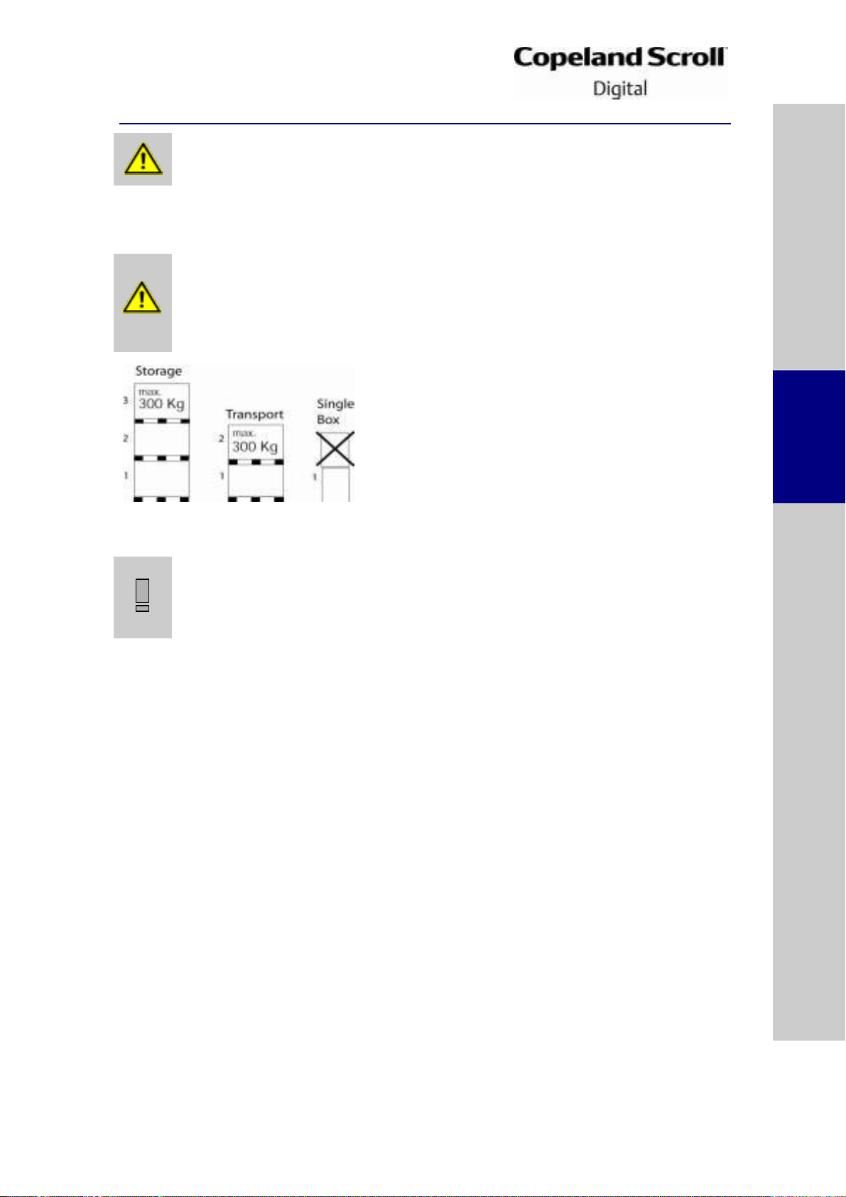
Risk of collapse! Personal injuries! Move compressors only with
appropriate mechanical or handling equipment according to weight. Keep in
the upright position. Stack pallets on top of each other when not exceeding
300 kg. Do not stack single boxes on top of each other. Keep the packaging
dry at all times.
IMPORTANT
Handling damage! Compressor malfunction! Only use the lifting eyes
whenever the compressor requires positioning. If the compressor has two
lifting tabs, both must be used for lifting. Using discharge or suction
connections for lifting may cause damage or leaks.
Safety
instructions
Product
description
Installation
Electrical
connection
Starting up &
operation
Maintenance &
repair
Dismantling &
disposal
3 Installation
3.1 Compressor handling
3.1.1 Transport and storage
Figure 5
3.1.2 Positioning and securing
For models ZBD58K* to ZBD114K* and ZFD41K5E, because oil might spill out of the suction
connection located low on the shell, the suction connection plug must be left in place until the
compressor is set into the unit. If possible, the compressor should be kept vertical during
handling. The discharge connection plug should be removed first before pulling the suction
connection plug to allow the dry air pressure inside the compressor to escape. Pulling the plugs
in this sequence prevents oil mist from coating the suction tube making brazing difficult. The
copper-coated steel suction tube should be cleaned before brazing. No object, eg, a swaging
tool should be inserted deeper than 51 mm into the suction tube or it might damage the suction
screen and motor.
3.1.3 Installation location
Ensure the compressors are installed on a solid level base.
3.1.4 Mounting parts
Four vibration absorber grommets are supplied with each compressor. They dampen the start-up
surge of the compressor and minimise sound and vibration transmission to the compressor base
during operation. The metal sleeve inside is a guide designed to hold the grommet in place. It is
not designed as a load-bearing member, and application of excessive torque to the bolts can
crush the sleeve. Its inner diameter is approximately 8.5 mm to fit, eg, an M8 screw. The
mounting torque should be 13 ± 1 Nm. It is critically important that the grommet is not
compressed.
If the compressors are mounted in tandem or used in parallel, then the hard mountings (bolt M9
5/16”) are recommended. The mounting torque should be 27 ± 1 Nm. It is possible to deliver
these hard mounting parts as a kit, or on request to deliver the compressor with these parts
instead of the rubber grommets.
C6.2.24/0215-0515/E 7
 Loading...