

YARWAY TempLowHT DESUPERHEATER
InstallatIon and MaIntenance InstructIons
Before installation these instructions must be fully read and understood
MODEL 59/69/79
ATTENTION WHEN PUTTING INTO OPERATION
Readjust ‘Stuffing box’ immediately as required
(see separate section). Leakage is out of guarantee.
INSTALLATION OF THE TempLowHT
DESUPERHEATER
Before installation, check the TempLowHT
Desuperheater, actuator and accessories for any
visible damage.
Check that the information on the documentation,
identification plate and tag number complies with
the order specification. Remove the TempLowHT
Desuperheater carefully from its packaging,
liftingby means of straps around the body.
Do not use the water inlet connection, yoke,
actuator or any of its accessories for lifting. Leave
the flange covers
until ready to install in the pipework.
WARNING
The hoisting lug is for the actuator only,
NOT for a total assembly!
When installing the TempLowHT
Desuperheater use gaskets and bolting
material in accordance with the relevant piping
code, for example ASME B31.1 or AD 2000/EN.
Place the gasket onto the mounting flange
and carefully insert the nozzle into the branch
pipe. Ensure that the spray cylinder is pointed
with the direction of the steam flow before
tightening the mounting bolts (see figure 3).
in place during transportation,
RECOMMENDATIONS
(acid cleaning ofsteam boilers)
Remove TempLowHT Desuperheaters from
thepiping prior to acid cleaning!
UNPACKING
The Yarway TempLowHT Desuperheater is
packed with the greatest of care in wooden
boxes or cartons for protection during handling
and transit to site. After hydrostatic testing,
the TempLowHT Desuperhater is flushed
through with a high grade of preservative to
protect machined and internal surfaces from
corrosion. If it is found, however, that damage
has occurred during shipment, then this should
be reported immediately to your forwarder or
Yarway representative.
Particular care should be taken when removing
the TempLowHT Desuperheater from its packing
and your special attention is required to check
carefully that no damage has occurred to flange
faces, threading, actuators, connecting pipes, etc.
(See figure 1).
NOTE
The TempLowHT Desuperheaters should be installed
free of ‘forces, moments and torques’.
The TempLowHT Desuperheater is provided
with a standard lower body length, as specified
in the contract drawing and the mounting
branch for the steam pipework must be
manufactured to suit. The length of this branch
should be such, that the centerline of the spray
cylinder is located on the centerline of the
steam pipe (± 5 mm).
The mounting branch should be 3” (DN 80) for
Model 59, 4” (DN 100) for Model 69 and 5” (DN125)
for Model 79 nominal bore, maximum pipe
schedule 160 for clearance purposes (check the
applicable power piping code). Check the certified
drawing for flange details.
© 2017 Emerson. All Rights Reserved.Emerson.com/FinalControl VCIOM-03239-EN 18/04
YARWAY TempLowHT DESUPERHEATER
InstallatIon and MaIntenance InstructIons
The minimum pipe run, required downstream
of the TempLowHT Desuperheater, varies
with each individual application and would
be specified by Yarway at the enquiry stage.
This straight run is needed to prevent erosion
due to impingement of water droplets against
pipewalls, valves and fittings and is normally
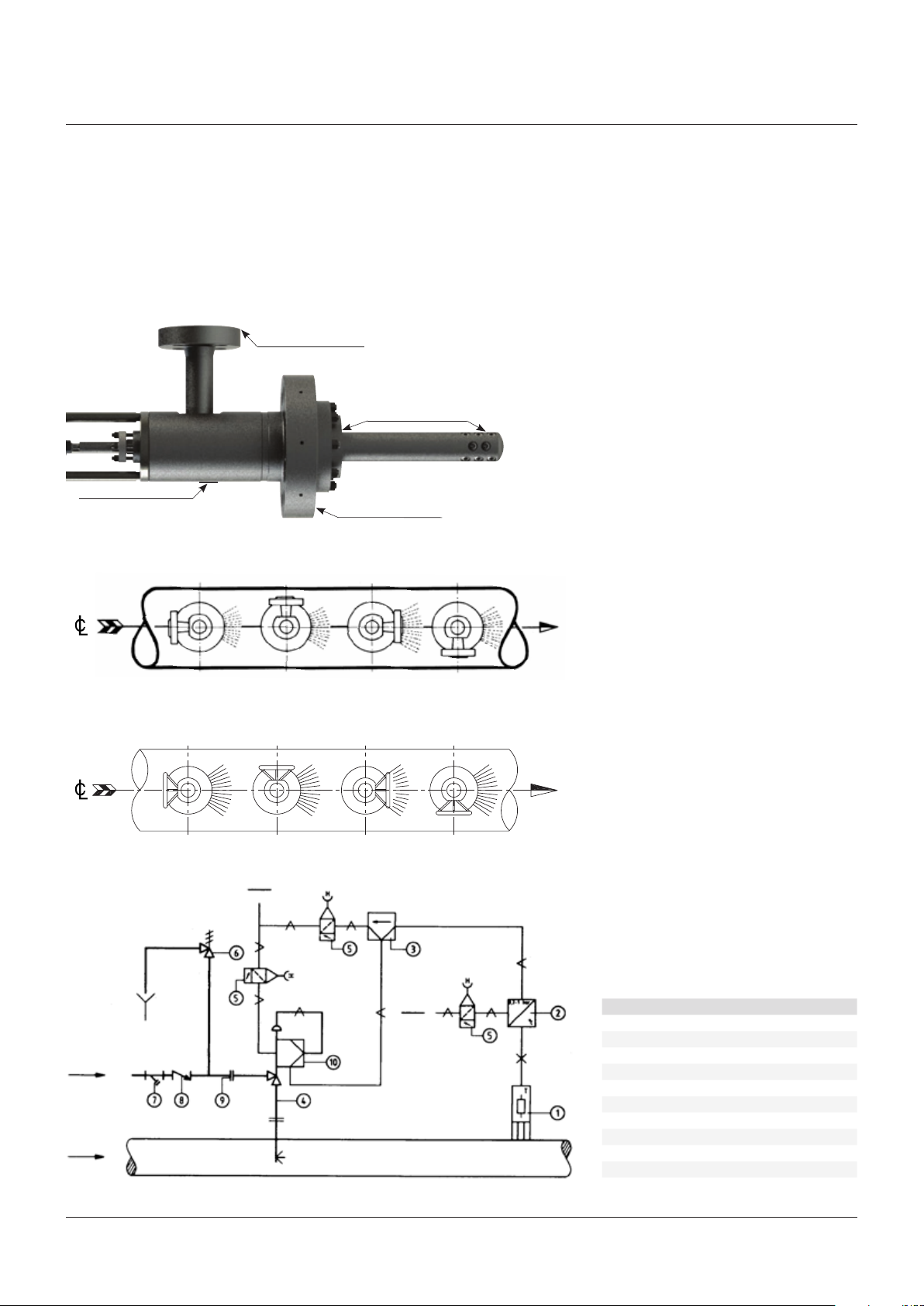
FIGURE 1 - MODEL 59/69/79
Check for damages
Identification plate
FIGURE 3
Water flange positions
Steam line
inthe order of 4 to 6 meters, as a minimum (no
upstream straight length is normally required).
The distance from the TempLowHT Desuperheater
to the temperature sensor is nominally 12to
15meters, although the distance specific to
theapplication would be advised by Yarway at
the enquirystage. Longerdistances will ensure
Check for damages
Check for damages
Steam flow
that full evaporation of the water will take place
at lowersteam velocities.
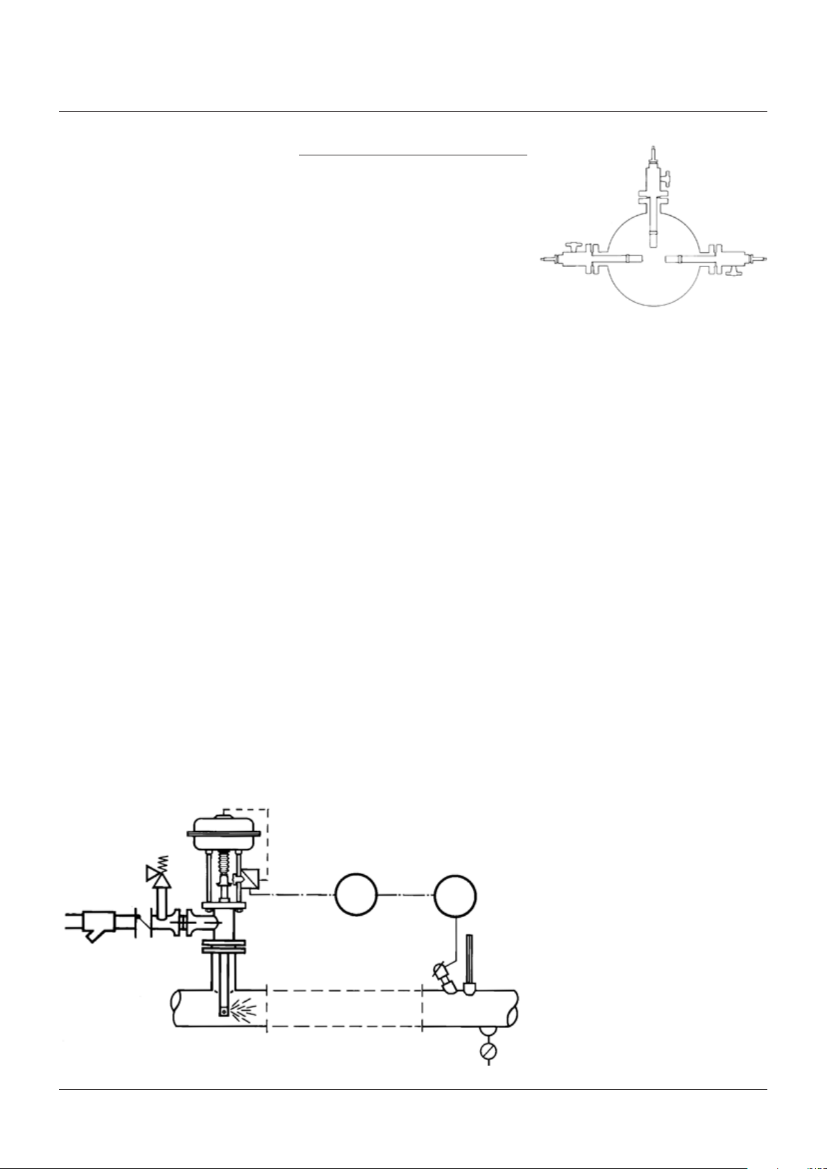
The temperature sensor should be located in
the upper half of the pipe, avoid branching of
the steam pipework between the TempLowHT
Desuperheater and the sensor (see figure 4).
Steam line
FIGURE 4
Water
Steam
FP9 FP12 FP3 FP6
Handwheel positions
HWW HWN HWE HWS
Air
Air
Steam flow
Item Description
1 Temperature sensor
2 Temperature transmitter
3 Temperature controller
4 TempLowHT Desuperheater
5 Air filter regulator
6 Safety relief valve
7 Strainer
8 Check valve
9 Flange
10 E/P-positioner
2
YARWAY TempLowHT DESUPERHEATER
InstallatIon and MaIntenance InstructIons
Pipe bends should always be of the long radius
type to assist in keeping the water droplets in
suspension, until complete evaporation has
taken place. Installation may be in vertical or
horizontal piping, but the direction of water
injection should always be with the steam flow.
The TempLowHT Desuperheater may be
mounted at 90° to the steam pipe, for all steam
flow orientations, but avoid installation in
the vertically downwards position, wherever
possible (see figure 5).
Yarway supplies the TempLowHT
Desuperheater as follows:
Identification number:
xx. 59. xxxxx - Forged type with 3” (DN 80)
mounting flange
xx. 69. xxxxx - Forged type with 4” (DN 100)
mounting flange
xx. 79. xxxxx - Forged type with 5” (DN 125)
mounting flange
NOTE
Horizontal orientated TempLowHT Desuperheater has
to be installed with a support for weightcompensation.
The water supply should be of a good quality;
clean and filtered, for example boiler feed
water and should have a constant pressure as
specified in the order documents. Each water
supply line should be protected with its own
individual strainer with a maximum element
perforation size of 0.1 mm (0.4 mm acceptable
for nozzles ‘E’ size and up).
Where there are positive shut-off components
in the water supply (including electric actuators)
then a safety relief valve of an approved type
should be fitted. As in the case of thesteam
pipework,
accordance with the relevant piping code.
Flushout the water line before connecting
to the TempLowHT Desuperheater mounting
flange (see figure 6).
use gasketing and bolting in
START-UP
Ensure that all components are installed
correctly. Connection of electrical supplies and
instrument air piping should be in accordance
with the manufacturer’s instruction manual.
Verify and adjust, ifnecessary, set points for
filter regulators and valve positioners, following
the manufacturer’s recommendations.
Similarly, calibrate thetemperature
transmitter/controller, verifying automatic
response to temperature changes.
Warm the steam main and open the
valve in the water supply. Check the
water pressure at the TempLowHT
Desuperheater. Verifytheoperation of the
temperature transmitter and controller by
manually increasing and decreasing the
output signal and observing indicated and
recordedtemperatures.
When satisfactory coordination between
instrument signals and temperature are
attained, adjustment of the set point can
be made and the system transferred to
automaticoperation.
It is recommended to record the various steam
coordinates, over a sustained period, to verify
operation, adjusting where necessary.
FIGURE 5
FIGURE 6
Check valve
Strainer
Safety valve
TC TT
3
 Loading...