

Page 1

Instruction Manual
HASXMDE-IM-EX
03/2012
Gas Analyzer
X-STREAM X2 Series
Flameproof Variation
For Use in Zone 1 and Division 2 Hazardous Areas
Instruction Manual Addendum
www.EmersonProcess.com
Page 2

ESSENTIAL INSTRUCTIONS
READ THIS PAGE BEFORE PROCEEDING!
Emerson Process Management (Rosemount Analytical) designs, manufactures and
tests its products to meet many national and international standards. Because these
instruments are sophisticated technical products, you MUST properly install, use, and
maintain them to ensure they continue to operate within their normal specications.
The following instructions MUST be adhered to and integrated into your safety program
when installing, using and maintaining Emerson Process Management (Rosemount
Analytical) products. Failure to follow the proper instructions may cause any one of the
following situations to occur: Loss of life; personal injury; property damage; damage to
this instrument; and warranty invalidation.
• Read all instructions prior to installing, operating, and servicing the product.
• If you do not understand any of the instructions, contact your Emerson Process
Management (Rosemount Analytical) representative for clarication.
• Follow all warnings, cautions, and instructions marked on and supplied with the
product.
• Inform and educate your personnel in the proper installation, operation, and
maintenance of the product.
• Install your equipment as specied in the Installation Instructions of the
appropriate Instruction Manual and per applicable local and national codes.
Connect all products to the proper electrical and pressure sources.
• To ensure proper performance, use qualied personnel to install, operate, update,
program, and maintain the product.
• When replacement parts are required, ensure that qualied people use replacement
parts specied by Emerson Process Management (Rosemount Analytical).
Unauthorized parts and procedures can affect the product’s performance, place the
safe operation of your process at risk, and VOID YOUR WARRANTY. Look-alike
substitutions may result in re, electrical hazards, or improper operation.
• Ensure that all equipment doors are closed and protective covers are in place,
except when maintenance is being performed by qualied persons, to prevent
electrical shock and personal injury.
The information contained in this document is subject to change without notice.
6th edition 03/2012
Rosemount Analytical
Process Gas Analyzer Center of Excellence
Emerson Process Management GmbH & Co. OHG
Industriestrasse 1
D-63594 Hasselroth
Deutschland
T +49 (0) 6055 884-0
F +49 (0) 6055 884-209
www.emersonprocess.de
Original Instruction Manual for the purpose
of the European Directive 94/9/EC.
Page 3

Instruction Manual
HASXMDE-IM-EX
03/2012
X-STREAM X2FD
Table of ConTenTs
Preamble S-1
Denitions S-1
Terms used in this manual ....................................................S-2
Symbols used on and inside the unit ............................................S-3
Symbols used in this manual ..................................................S-4
Safety Instructions S-5
Intended Use Statement .....................................................S-5
General Safety Notice / Residual Risk ..........................................S-5
Special Conditions for Safe Use ...............................................S-5
Authorized Personnel .......................................................S-6
Additional Literature. . . . . . . . . . . . . . . . . . . . . . . . . . . . . . . . . . . . . . . . . . . . . . . . . . . . . . . . . S-6
Chapter 1 Technical Description 1-1
1.1 Overview .............................................................1-1
1.2 Design Features .......................................................1-1
1.3 Protective Measures in Detail .............................................1-2
1.4 High Pressure Option / Purge Option .......................................1-3
1.5 Explosion Protection Compliances .........................................1-4
1.5.1 Special conditions for safe use ..........................................1-5
1.6 Nameplate Label .......................................................1-6
1.7 Technical Data. . . . . . . . . . . . . . . . . . . . . . . . . . . . . . . . . . . . . . . . . . . . . . . . . . . . . . . . . 1-7
1.8 Measurements Specications ............................................1-14
1.9 Vapor Recovery Application (Simultaneous Measurement of CH4 and Non-CH4) ....1-18
Table of Contents
TOC
Chapter 2 Installation 2-1
2.1 Scope of Supply .......................................................2-1
2.2 Installing the Analyzer ...................................................2-2
2.3 Connecting Gas Lines ...................................................2-5
2.3.1 Special Conditions ...................................................2-6
2.3.2 Gas Conditioning ....................................................2-8
2.4 Electrical Installation ....................................................2-9
Chapter 3 Startup 3-1
3.1 Final Check ...........................................................3-1
3.2 Performing a Leak Test ..................................................3-2
3.3 Switching On ..........................................................3-3
3.4 Symbols used .........................................................3-4
Emerson Process Management GmbH & Co. OHG TOC-1
Page 4

Instruction Manual
X-STREAM X2FD
Table of Contents
3.5 The user interface ......................................................3-5
3.5.1 Display ............................................................3-6
3.5.2 Status LED .........................................................3-6
3.5.3 Keys 3-7
3.6 Software .............................................................3-9
3.6.1 Navigating and editing ................................................3-9
3.6.2 Access levels ...................................................... 3-11
3.6.3 Special messages ...................................................3-12
3.7 Powering up .........................................................3-13
3.7.1 Boot sequence .....................................................3-13
3.7.2 Measurement display ................................................3-13
3.8 Selecting the language .................................................3-14
3.9 Calibrating the analyzer ................................................3-15
3.9.1 Preparing Calibrations ...............................................3-16
3.9.2 Manual Calibration ..................................................3-18
HASXMDE-IM-EX
03/2012
Chapter 4 Service and Maintenance 4-1
4.1 Verications and Tests ..................................................4-3
4.1.1 Routine Tests on Analyzer .............................................4-3
4.1.2 Tests on Flame Arrestors ..............................................4-4
4.2 Replacement of Parts ...................................................4-6
4.3 Vapor Recovery Application - Special Information .............................4-8
4.3.1 Determining the converter efciency .....................................4-9
4.3.2 Replacement Instructions .............................................4-10
4.3.3 Failure Situation ....................................................4-14
4.4 Perform a Calibration ..................................................4-15
4.4.1 Manual Calibration ..................................................4-16
Chapter 5 Dismounting and Disposal 5-1
5.1 Dismounting and Diposal of the Analyzer ....................................5-1
Appendix A-1
A.1 EC Declaration of Conformity .............................................A-2
A.2 ATEX EC Type Examination Certicate .....................................A-3
A.3 CSA Certicate of Compliance ...........................................A-12
A.4 Block diagram ........................................................A-19
A.5 Assignment of Terminals and Sockets .....................................A-24
Emerson Process Management GmbH & Co. OHGTOC-2
Page 5

Instruction Manual
HASXMDE-IM-EX
03/2012
X-STREAM X2FD
Index of fIgures
Fig. 1-1: Frontal View .......................................................1-1
Fig. 1-2: Bottom view .......................................................1-2
Fig. 1-3: Nameplate Label Details (exemplary) ...................................1-6
Fig. 1-4: Dimensions. . . . . . . . . . . . . . . . . . . . . . . . . . . . . . . . . . . . . . . . . . . . . . . . . . . . . . . . 1-7
Fig. 1-5: Signals terminals ..................................................1-12
Fig. 1-6: Power terminals / fuse holders ........................................1-13
Fig. 1-7: Vapor Recovery Gas Flow Diagram ....................................1-18
Fig. 2-1: Scope of Supply ....................................................2-1
Fig. 2-2: Dimensions. . . . . . . . . . . . . . . . . . . . . . . . . . . . . . . . . . . . . . . . . . . . . . . . . . . . . . . . 2-4
Fig. 2-3: Flame arrestor installed into instrument enclosure. . . . . . . . . . . . . . . . . . . . . . . . . . 2-5
Fig. 2-4: Flame arrestor elements, exemplarly considering FA 01 .....................2-5
Fig. 2-5: Exemplary diagram for a single channel unit with purge option ................2-6
Fig. 2-6: Exemplary diagram for a single channel instrument for high gas pressure ......2-7
Fig. 2-7: Label with fastening torques, installed at the instrument ....................2-7
Fig. 2-8: Allocation of terminals ..............................................2-13
Fig. 2-9: Terminals block X1 - analog signals and relay outputs 1-4 ..................2-15
Fig. 2-10: Terminals block X1 - Modbus interface ................................2-16
Fig. 2-11: Modbus Interface - Ethernet connector ................................2-17
Fig. 2-12: Terminal blocks X4.1 and X4.2 - Digital inputs and outputs ................2-18
Fig. 2-13: Power terminals ..................................................2-19
Fig. 2-14: Equipotential bonding conductor terminal ..............................2-20
Table of Contents
TOC
Fig. 3-1: Leak Testing with U-turn Manometer ....................................3-2
Fig. 3-2: Front Panel ........................................................3-5
Fig. 4-1: Leak Testing with U-tube Manometer (Flame arrestor) ......................4-5
Fig. 4-2: Pressure Drop Test ..................................................4-5
Fig. 4-3: Vapor recovery application setup .......................................4-8
Fig. 4-4: Converter assembly ................................................4-10
Fig. 4-5: Converter assembly details ..........................................4-10
Fig. 4-6: Heated jacket .....................................................4-11
Fig. 4-7: Converter, laid open ................................................4-11
Fig. 4-8: Converter lling sequence ...........................................4-12
Fig. 4-9: Jacket in converter assembly ........................................4-13
Fig. 4-10: Heated jacket ....................................................4-13
Fig. 4-11: Converter metallic cover ...........................................4-13
Fig. 4-12: Location of Overtemperature Protection Device .........................4-14
Emerson Process Management GmbH & Co. OHG TOC-3
Page 6

Instruction Manual
X-STREAM X2FD
HASXMDE-IM-EX
03/2012
Index of Tables
Tab. 1-1: Gas Components and Measuring Ranges, examples ......................1-14
Tab. 1-2: NDIR/UV/VIS, TCD - Standard Measurement Performance Specications .....1-15
Tab. 1-3: Trace Moisture - Standard Measurement Performance Specications .........1-15
Tab. 1-4: Oxygen - Standard Measurement Performance Specications ..............1-16
Tab. 1-5: Special Performance Specications for Gas Purity Measurements ...........1-17
Emerson Process Management GmbH & Co. OHGTOC-4
Page 7
Instruction Manual
HASXMDE-IM-EX
03/2012
X-STREAM X2FD
PREAMBLE
This instruction manual provides information about installing, operating and maintaining/
servicing X-STREAM X2 series gas analyzers in hazardous (classied) areas and shall be
read in conjunction with the basic analyzer instruction manual only!
This instruction manual covers several X-STREAM X2FD series analyzer variations and
therefore may describe congurations and/or options not part of your specic analyzer.
Safety Instructions
DEFINITIONS
The following denitions apply to WARNINGS, CAUTIONS and NOTES found throughout
this publication.
HIGHLIGHTS AN OPERATION OR MAINTENANCE PROCEDURE,
PRACTICE, CONDITION, STATEMENT, ETC.
If not strictly observed, could result in injury, death, or long-term health hazards of
personnel.
HIGHLIGHTS AN OPERATION OR MAINTENANCE PROCEDURE,
PRACTICE, CONDITION, STATEMENT, ETC.
If not strictly observed, could result in damage to or destruction of equipment, or loss
of effectiveness.
S
NOTE
Highlights an essential operating procedure, condition or statement.
Emerson Process Management GmbH & Co. OHG S-1
Page 8

X-STREAM X2FD
Instruction Manual
HASXMDE-IM-EX
03/2012
TERMS USED IN THIS MANUAL
ATEX
Directive 94/9/EC, commonly called the
ATEX („Atmosphères Explosibles“) directive,
dealing with equipment intended to be used
in potentially explosive atmospheres.
This directive is valid for equipment to be
sold into and/or installed and operated in the
European Union (EU).
Division 2
Where ignitable concentrations of ammable
gases are not likely to exist under normal
operating conditions (similiar to Zone 2).
Explosive Gas(es)
Flammable Gases and gas mixtures in a mixture with air within the explosive limits.
Flammable Gas(es)
Gases and gas mixtures are assigned to be
ammable if they might become ignitable
when in a mixture with air.
Infallible Containment
This term is derived from the standards of
explosion protection especially from the requirements for pressurized housings: thus an
infallible containment can be characterized
by no intended leakage into the gas paths
enabling gas to enter the inner compartment
of the analyzer housing.
Intrinsically Safe Cell (IS Cell)
Cells supplied with an intrinsically safe power
signal, approved by a Test Institute, to operate
with explosive gases.
The design ensures the IS cells remains safe
even in case of failure and explosive gases
are not ignited.
Lower Explosion Limit (LEL)
Volume ratio of ammable gas in air below
which an explosive gas atmosphere will not
be formed: the mixture of gas and air lacks
sufcient fuel (gas) to burn.
Protection Class IP66 / NEMA 4X
Both terms are used to specify conditions for
equipment to be installed outdoor.
IP stands for Ingress Protection, the rst num-
ber species protection against solid objects
(6. = dust tight) while the second number
species the degree of protection against
liquids (.6 = heavy seas).
NEMA stands for National Electrical Manuf-
acturers Association. 4X species a degree
of protection to personnel against incidental
contact with the enclosed equipment; to provide a degree of protection against falling dirt,
rain, sleet, snow, windblown dust, splashing
water, and hose-directed water; and that will
be undamaged by the external formation of
ice on the enclosure
Upper Explosion Limit (UEL)
Volume ratio of ammable gas in air above
which an explosive gas atmosphere will not
be formed: the mixture of gas and air is too
rich in fuel (decient in oxygen) to burn.
Zone 1
Where ignitable concentrations of ammable
gases can exist some of the time under normal operating conditions.
(A guideline value [not part of a standard ] is
10 to 1.000 hours per year.)
Zone 2
Where ignitable concentrations of ammable
gases are not likely to exist under normal
operating conditions.
(A guideline value [not part of a standard ] is
less than 10 hours per year.)
Emerson Process Management GmbH & Co. OHGS-2
Page 9
Instruction Manual
HASXMDE-IM-EX
03/2012
X-STREAM X2FD
Symbols used on and inside the unit
Wherever one or more of the following symbols appear on or inside the instrument, be careful
and read the instructions given in the accompanying manuals!
Strictly observe the given warnings, instructions and information to minimize hazards!
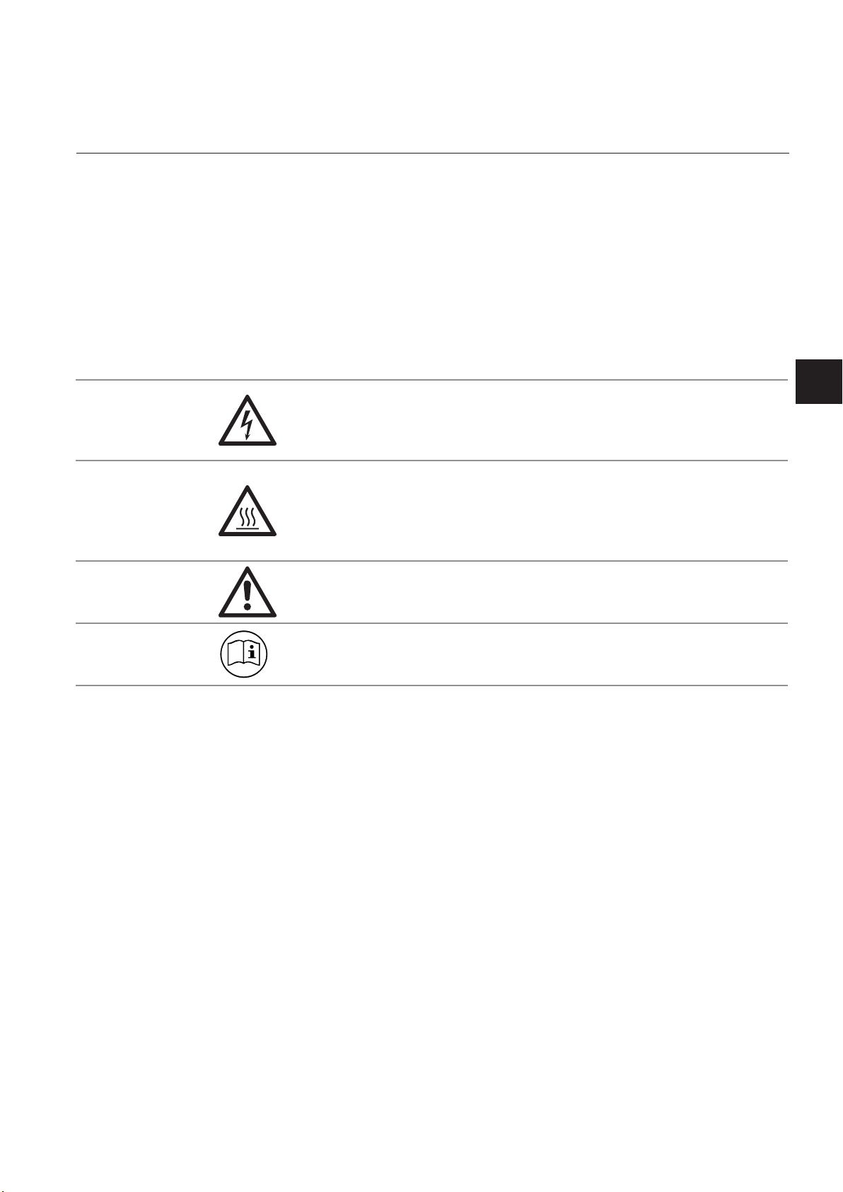
This symbol at the instrument ... ... means
dangerous voltages may be accessible. Remo-
ving covers is permitted only, if the instrument is
disconnected from power - and even in this case
by qualied personnel only!
hot surfaces may be accessible. Removing
covers by qualied personnel is permitted only,
if the instrument is disconnected from power.
Nevertheless several surfaces may remain hot
for a limited time.
more detailled information available: see in-
struction manual before proceeding!
more detailled information available: see in-
struction manual before proceeding!
Safety Instructions
S
Emerson Process Management GmbH & Co. OHG S-3
Page 10
Instruction Manual
X-STREAM X2FD
HASXMDE-IM-EX
03/2012
Symbols used in this manual
Where one or more of the following symbols appear within this manual, carefully read the related information and instructions!
Strictly observe the given warnings, instructions and information to minimize hazards!
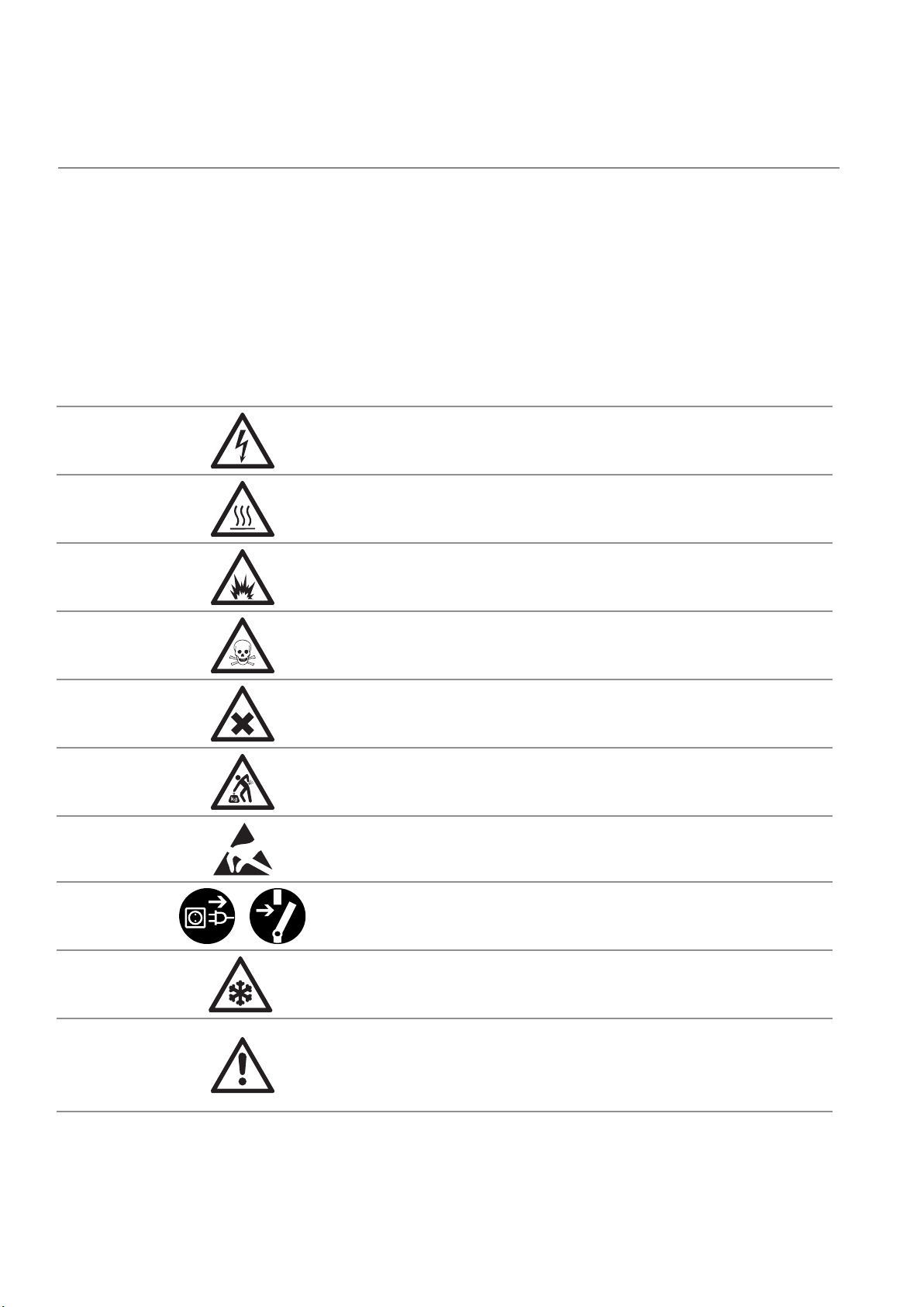
This symbol used in the manual ... ... means
dangerous voltages may be exposed
hot surfaces may be exposed
possible danger of explosion
toxic substances may be present
substances harmful to health may be present
indicates notes relating to heavy instruments
electrical components may be destroyed by
electrostatic discharges
units must be disconnected from the power
source
indicates special instructions or information for
operation at low temperatures.
indicates basic conditions or procedures are
being described.
This symbol may also indicate information impor-
tant for achieving accurate measurements.
Emerson Process Management GmbH & Co. OHGS-4
Page 11

Instruction Manual
HASXMDE-IM-EX
03/2012
X-STREAM X2FD
SAFETY INSTRUCTIONS
Intended Use Statement
X-STREAM X2 series gas analyzers are intended to be used as analyzers for industrial purposes.
They must not be used in medical, diagnostic or life support applications.
Using X-STREAM X2 analyzers as safety devices is prohibited where redundancy and/or SIL
classication or equivalent is needed.
No independent agency certications or approvals are to be implied as covering such applications!
Safety Instructions
General Safety Notice / Residual Risk
If this equipment is used in a manner not specied in these instructions, protective systems may
be impaired.
Despite of incoming goods inspections, production control, routine tests and application of state-
of-the-art measuring and test methods, an element of risk remains when operating a gas analyzer!
Even when operated as intended and observing all applicable safety instructions some residual
risks remain, including, but not limited to, the following:
• An interruption of the protective earth line, e.g. in an extension cable, may result in risk to
the user.
• Live parts are accessible when operating the instrument with doors open or covers removed.
• The emission of gases hazardous to health may even be possible when all gas connections
have been correctly made.
Avoid exposure to the dangers of these residual risks by taking particular care when installing,
operating, maintaining and servicing the analyzer.
Special Conditions for Safe Use
• Only specied screws M16x45 ISO 4762
A2-70 as specied in the maintenance
section of this manual shall be used (spare
part # 42716945).
• Vapor recovery application:
Pressure of gases not to exceed 1100 hPa.
Concentrations of gases must be below
25 % LEL.
S
• The ame joints correspond to the drawing
No. 4.271-7112/1 and do not comply with
the dimensions mentioned into the Tab. 1
and Tab. 2 of EN 60079-1 ed.2.
• The gas path for the sample gas shall be
equipped with additional appropriate ame
arrestors in case of gas pressure above
1100 hPa to 1500 hPa.
• Appropriate certied cable glands shall be
used in accordance with IEC/EN 60079-14.
Emerson Process Management GmbH & Co. OHG S-5
• Depending on the particular application all
approbriate safety instructions mentioned
in this instruction manual on hand must
be considered!
• Take special care of formation of ammable gas at the outlet of breathing and/or
purging devices, if the sample gas con-
centration is above 25% LEL! If need be,
such outlets have to end in a safe area!
Page 12

Instruction Manual
X-STREAM X2FD
Safety Instructions
HASXMDE-IM-EX
03/2012
Authorized Personnel
In-depth specialist knowledge is an absolutely necessary condition for working with and on the
analyzer.
Authorized personnel for installing, operating, servicing and maintaining the analyzer are instructed
and trained qualied personnel of the operating company and the manufacturer.
It is the responsibility of the operating company to
• train staff,
• observe safety regulations,
• follow the instruction manual.
Operators must
• have been trained,
• have read and understood all relevant sections of the instruction manual before commencing
work,
• know the safety mechanisms and regulations.
To avoid personal injury and loss of property, do not install, operate, maintain or service this instru-
ment before reading and understanding this instruction manual and receiving appropriate training.
Additional Literature
This manual covers aspects specic for using ameproof X-STREAM X2FD gas analyzers
in hazardous (classied) areas, only.
For comprehensive information on operating and maintain/service the instrument in a
safe manner it is MANDATORY to read all additional instruction manuals, if not provided
as printed version, see the accompanying USB stick for an electronic version (PDF)!
The following instruction manuals are available and/or referenced within this manual at hand:
HASX2E-IM-HS X-STREAM X2 series instruction manual
HASICx-IM-H Infallible Containment
The original manufacturer's cable gland or conduit instruction manual, depending on what is used.
Contact your local service center or sales ofce when missing documents.
SAVE ALL INSTRUCTIONS FOR FUTURE USE!
Emerson Process Management GmbH & Co. OHGS-6
Page 13
Instruction Manual
HASXMDE-IM-EX
03/2012
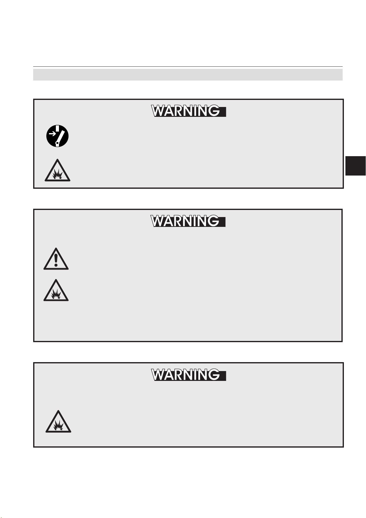
Do not open instrument when energized.
X-STREAM X2FD
Safety Instructions
POSSIBLE EXPLOSION HAZARD
Ensure that external circuitry is disconnected or de-energized before
opening the instrument.
Ensure that all gas connections are made as labeled and are leak free.
Improper gas connections could result in explosion and death.
EXPLOSION HAZARD BY MODIFICATION
Any addition, substitution, or replacement of components installed on or
in this device, must be certied to meet the hazardous area classication
that the device was certied to prior to any such component addition,
substitution, or replacement. In addition, the installation of such device or
devices must meet the requirements specied and dened by the hazardous
area classication of the unmodied device.
Any modications to the device not meeting these requirements, will void
the product certication(s).
Contact Emerson Process Management‘s customer service center for
return authorization.
Safety Instructions
S
EXPLOSION HAZARD
The X-STREAM X2FD analyzer may utilize not only sample gas but one or
more pressurized carrier gases and/or calibration gases.
If an external owmeter is required for ow control, legislative requirements
and instructions for installation in hazardous (classied) areas must be
considered.
Emerson Process Management GmbH & Co. OHG S-7
Page 14
X-STREAM X2FD
Installation and connecting mains and signal cables are subject to qualied
personnel only taking into account all applicable standards and legislative
requirements!
Failure to follow may cause warranty invalidation, property damage and/or
personal injury or death! Connecting mains and signal cables to internal
srew terminals requires working at open housing near life parts!
Installation of this instrument is subject to qualied personnel only, familiar
with the resulting potential risks!
The gas analyzers do not provide a mains power switch and are operable
when connected to power.
Instruction Manual
HASXMDE-IM-EX
03/2012
Safety Instructions
ELECTRICAL SHOCK HAZARD
The gas analyzers do not provide a mains switch! A mains switch or
circuit breaker (to comply with IEC 60947-1 /-3) has to be provided in the
building installation. This switch has to be installed near by analyzer, must
be easily operator accessible and has to be assigned as disconnector for
the analyzer.
EXPLOSION and ELECTRICAL SHOCK HAZARD
These instruments provide a protective earth terminal. To prevent electrical
shock and explosion hazards, the instrument must be connected to a
protective earth.
Therefore the instrument has to be connected to mains by using a three
wire mains cable with earth conductor!
Any interruption of the earth connector inside or outside the instrument
or disconnecting the earth terminal may cause potential electrical shock
hazard!
Intended interruption of protective earth connections is not permitted!
Emerson Process Management GmbH & Co. OHGS-8
Page 15
Instruction Manual
HASXMDE-IM-EX
03/2012
Temperatures inside an analyzer for VAPOR RECOVERY applications
exceed the analyzer‘s temperature classication for hazardous areas!
Special conditions apply to handling and operating this analyzer, consider
the safety instructions at the beginning of this manual!
The analyzer model X-STREAM X2FD, to which this manual relates, intended
to be wall mounted and/or outdoor installed, weighs up to approx. 63 kg
(139 lbs), depending on included options!
X-STREAM X2FD
Safety Instructions
EXPLOSION HAZARD BY HOT COMPONENTS
Safety Instructions
S
HEAVY INSTRUMENT
Use two people and/or suitable tools for transportation and lifting these
instruments!
Take care to use anchors and bolts specied to be used for the weight of
the units!
Take care the wall or stand the unit is intended to be installed at is solid
and stable to hold the units!
HIGH TEMPERATURES
While working at internal components hot surfaces may be accessible
after the instrument has been disconnected from power!
, even
HOW TO STAY IN COMPLIANCE WITH THE
EUROPEAN DIRECTIVE 94/9/EC ("ATEX") WHEN PERFORMING GAS
ANALYSIS WITHIN A FLAMEPROOF ENCLOSURE.
Special conditions apply to using a ameproof enclosure analyzer under the scope of the
"European Directive for Equipment used in Explosive Atmosphere" (Directive 94/9/EC;
ATEX). To stay compliant to the directive consider the following clarication sheet released
by the European ATEX Notied Body Group (see next page):
Emerson Process Management GmbH & Co. OHG S-9
Page 16
X-STREAM X2FD
Instruction Manual
HASXMDE-IM-EX
03/2012
Safety Instructions
Emerson Process Management GmbH & Co. OHGS-10
Page 17
Instruction Manual
HASXMDE-IM-EX
03/2012
1.1 Overview
X-STREAM X2FD
Chapter 1
Technical Description
The new X-STREAM X2FD gas analyzer is
designed to be used in hazardous areas.
Its ameproof enclosure can be installed at
Zone 1 and Division 2 locations without the
need of any additional protective measures,
e.g. purge gas supply.
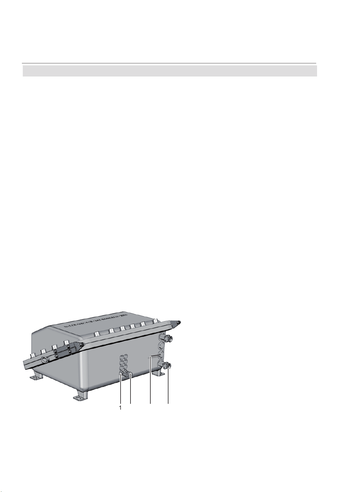
1.2 Design Features
Packaged into a cast aluminum enclosure,
the X-STREAM X2FD gas analyzer provides
all the measurement options available for general purpose instruments, but for installation
at locations, where explosive gas atmosphere
might be present frequently (Zone 1) or occasionally (Zone 2, Division 2).
The basic concept used to protect the surrounding atmosphere from being ignited if an
internal failure results in high temperatures,
ames or even an explosion, is to keep the
explosion inside the enclosure and quench all
ames possibly passing through the ange.
To provide adequate explosion protection the
X-STREAM X2FD analyzer features:
•
a cast aluminum enclosure, designed to
• withstand an internal explosion,
• quench ames resulting from an internal
explosion (thus preventing a surroun-
ding explosive atmoshere from being
ignited).
• ame arrestors avoiding ame transmissi-
on from the gas paths into the surrounding
atmosphere.
• approved cable glands (option: conduits),
protecting the cable inlets and outlets.
Techn. Description
1
3
5
2
6
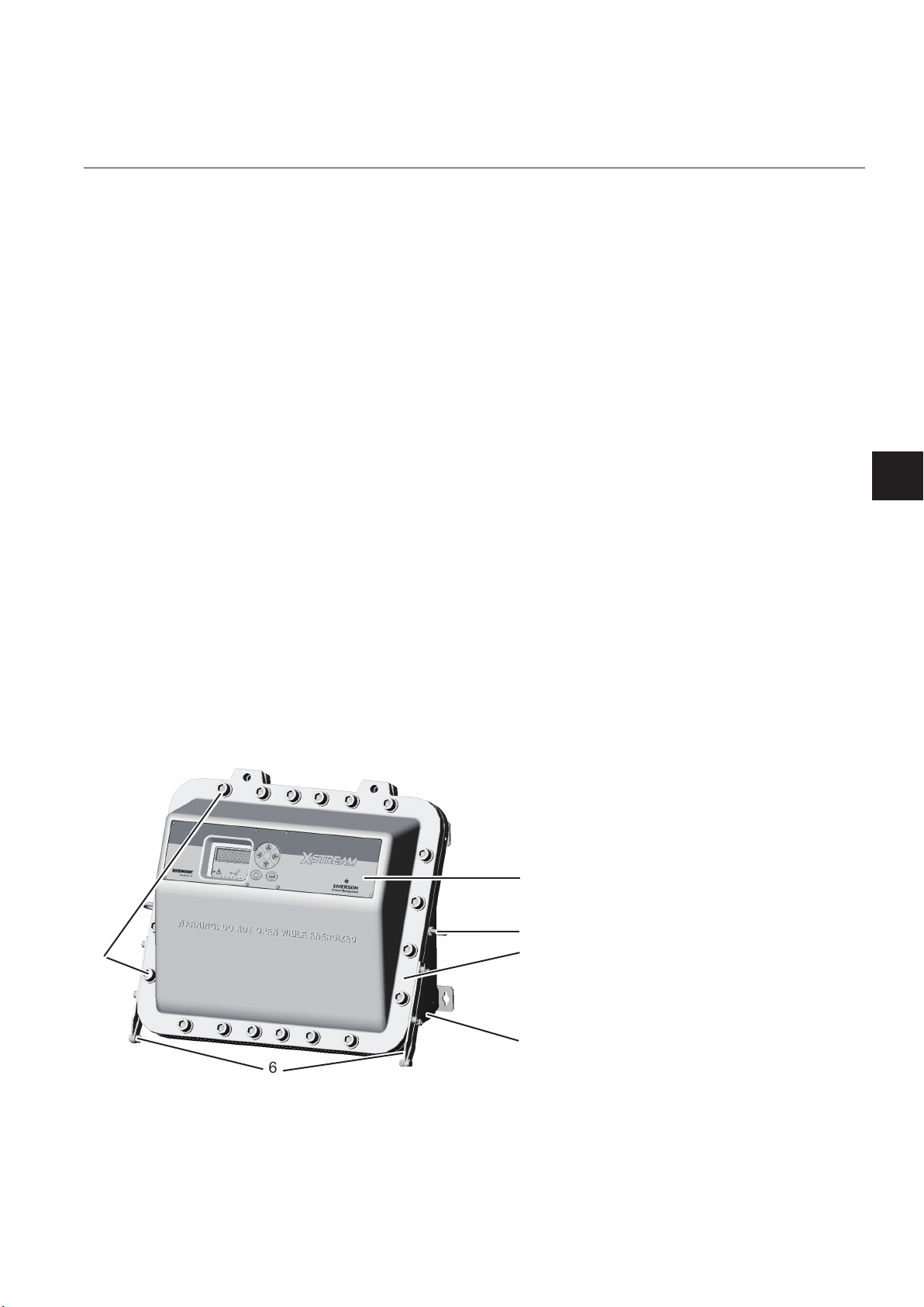
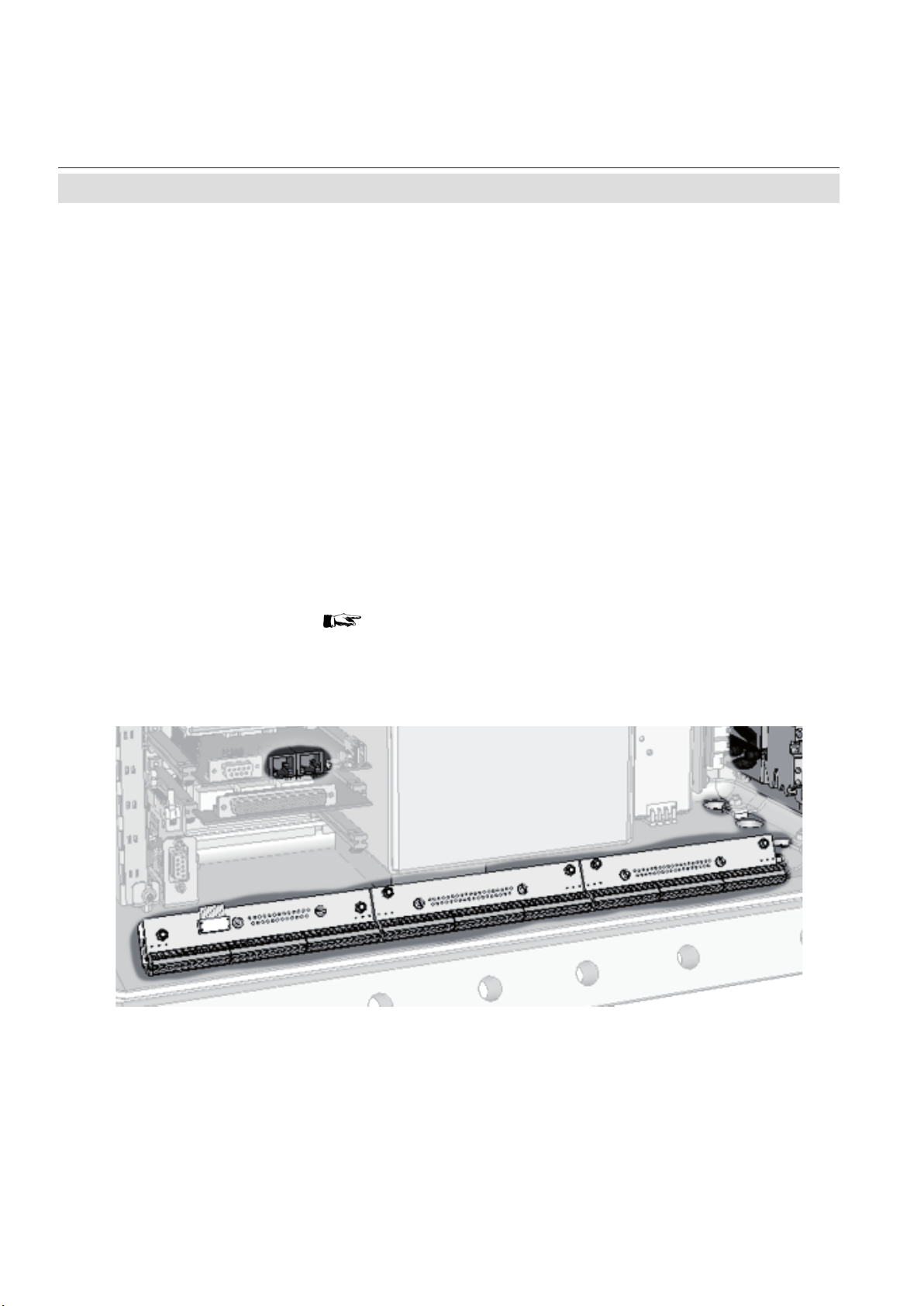
Fig. 1-1: Frontal View
Emerson Process Management GmbH & Co. OHG 1-1
4
1
1: Enclosure base
2: Screws
3: Enclosure cover
4: Flange
5: Eyebolts for lifting
6: Hinges
Page 18
X-STREAM X2FD
1.3 Protective Measures in Detail
1.3 Protective Measures in Detail
The cast aluminum enclosure consists of
two parts: base and cover, connected by
hinges.
The area where the two parts are in contact
is designed to work as a ange, quenching
ames entering the small path between them.
When operated, the analyzer enclosure has to
be closed and secured by 20 screws evenly
arranged all over the ange. The only ope-
nings penetrating the enclosure are threads,
to be used for gas and cable in- and outlets:
Instruction Manual
HASXMDE-IM-EX
03/2012
Cables are fed into the enclosure utilizing up
to 4 cable glands, located at the enclosure`s
bottom right side.
For installation in North America cable glands
are replaced by a combination of conduits and
metric-to-NPT thread adapters.
All threads provide a ame path of a length
ensuring that possibly entering ames are
quenched before reaching the external at-
mosphere.
Depending on the measurement application
the instrument provides up to 8 gas in- and
outlets, each protected by an approved ame
arrestor. These arrestors are installed into
threads at the bottom side of the enclosure
base. Two tting sizes are available for ex-
ternal connection of gas pipes with 3,18 mm
(1/8“) or 6,35 mm (1/4“) outer diameter (OD).
Optionally a clamping ring for 6 mm OD may
be used, replacing the 6,35 mm version.
Unused threads must be closed with plugs
when the instrument is operated to ensure
explosion protection.
Note!
See the X-STREAM X2 series instruction
manual for more information about common
X-STREAM X2 series gas analyzers features and special features of the X-STREAM
X2FD.
1: Plugged when not used
2: Gas tting (part of ame arrestor)
3: Plug
4: Cable gland (or conduits)
Fig. 1-2: Bottom view
1 2 3 4
Emerson Process Management GmbH & Co. OHG1-2
Page 19
Instruction Manual
HASXMDE-IM-EX
03/2012
1.4 High Pressure Option / Purge Option
1.4 High Pressure Option / Purge Option
Normally ameproof housings are permitted
to operate under atmospheric conditions only,
that is within an ambient pressure range between 800 and 1100 hPa.
For analyzers this pressure range also applies
to the gas pressure within the containment
system. While the lower limit is not critical,
the higher is, because it lowers the permitted
sample gas (and calibration gases) pressures
by 400 hPa, compared to general purpose
analyzers. This results in higher requirements
for the sample handling system, as it has to
safely reduce the process gas pressure to the
permitted range.
Another aspect to take care for when ope-
rating ameproof analyzers is the option of
applying a purge gas to the enclosure when
measuring low concentrations of gases, being
constituent of the ambient air: The ambient air
inside the analyzer enclosure cross interfe-
rese with the sample gas and inuences the
measuring results. By purging the housing
with a gas free of the measured component,
this can be avoided, but could increase the
pressure inside the analyzer and so would
violate the atmospheric pressure condition.
X-STREAM X2FD analyzers have been
subjected to additional tests to support both
situations:
X-STREAM X2FD
ximum permitted ow is 1,5 l/min, depending
on the installed measurement system lower
limits may apply.
The gas paths need additionally to be protected by suitable inline ame arrestors, de-
signed and approved for the applied higher
gas pressure and for the area of installation.
These ame arrestors need to be installed
outside the analyzer and in addition to the
ame arrestors provided by the analyzer.
Note!
The external inline ame arrestors are not
subject of the analyzer certication and may
be provided by the customer, or optionally by
EMERSON PROCESS MANAGEMENT.
A separate analyzer ame arrestor has to be
installed, operating as a breathing device and
thus limiting the increase of pressure in the
enclosure in case of internal leakage.
Purging the housing with clean gas when
measuring low concentrations
The maximum permitted gas ow is 2 l/min.
The gas must be supplied via a separate
ame arrestor. Another ame arrestor must
be installed, operating as a breathing device
and so limiting the increase of pressure in
the enclosure.
Techn. Description
1
• higher sample and calibration gas pres-
sures
as well as
• purging the housing with a gas for best
measuring results at low concentrations.
To permit this, special additional conditions
must be taken into account:
Higher sample and calibration gas pressures
Higher gas pressure is specied to be within
the range of 1100 hPa to 1500 hPa. The ma-
Emerson Process Management GmbH & Co. OHG 1-3
EXPLOSION HAZARD
When making use of any of
above mentioned options, take
care of the special conditions
for safe use given on the next
page!
Page 20

X-STREAM X2FD
1.5 Compliances
1.5 Explosion Protection Compliances
Instruction Manual
HASXMDE-IM-EX
03/2012
This product is available in two different variations, separately certied by agencies for the
use in hazardous (classied) areas:
The one version, to be equipped with cable
glands, is certied by Fyzikálně technický
zkušební ústav, s.p (FTZÚ), an European
Notied Body under the Directive 94/9/EC
(„ATEX“) and conforms to the provisions of
EN 60079-0 and EN 60079-1. See appendix for a copy of the EC type examination
certicate.
The second variation, to be equipped with
metric-to-NPT adapters and conduits (these
components are not part of the instrument
certication), is certied by the Canadian
Standards Association, an „OSHA Nationally Recognized Testing Laboratory“
(NRTL), for Canada and USA and conforms
to the provisions of CAN/CSA-E60079-0:02
(R2006), CAN/CSA-E60079-1:02 (R2006),
ANSI/ISA-12.00.01-2002 (IEC 60079-0 Mod),
ANSI/ISA-12.22.01-2002 (IEC 60079-1 Mod).
Furthermore, these X-STREAM X2FD analy-
zers are certied for use in Class I, Division 2,
Group BCD T3 areas.
See appendix for a copy of the CSA Certicate
of Compliance.
The following certication markings apply to
the products:
European Union (EU, ATEX)
Category 2, Zone 1:
Ex d IIB+H2 T4 Gb
EC ATEX Type Examination Certicate:
FTZU 08 ATEX 0028 X.
IECEx
Ex d IIB+H2 T4 Gb
Conforms to the provisions of the „Equipment
intended for use in Potentially Explosive At-
mospheres (ATEX)“ Directive 94/9/EC, EMC
Directive 2004/108/EC and CE Directive
93/68/EEC.
USA
Class I, Zone 1, AEx d IIB+H2 T3
Class I, Division 2, Group BCD T3
IECEx certication enables worldwide approvals with minimized need of testing.
Canada
Class I, Zone 1, Ex d IIB+H2 T3
Certicate of Compliance 1714037X
Emerson Process Management GmbH & Co. OHG1-4
Page 21

Instruction Manual
HASXMDE-IM-EX
03/2012
1.5 Compliances
1.5.1 Special conditions for safe use
X-STREAM X2FD
• Only specied screws M16x45 ISO 4762
A2-70 as specied in the maintenance
section of this manual shall be used (spare
part # 42716945).
• The ame joints correspond to the drawing
No. 4.271-7112/1 and do not comply with
the dimensions mentioned into the Tab. 1
and Tab. 2 of EN 60079-1 ed.2.
• The gas path for the sample gas shall be
equipped with additional appropriate ame
arrestors in case of gas pressure above
1100 hPa to 1500 hPa.
• Appropriate certied cable glands shall be
used in accordance with IEC/EN 60079-14.
• Vapor Recovery application:
Pressure of gases not to exceed 1100 hPa.
Concentrations of gases must be below
25 % LEL.
• Depending on the particular application all
approbriate safety instructions mentioned
in this instruction manual on hand must
be considered!
• Take special care of formation of ammable gas at the outlet of breathing and/or
purging devices, if the sample gas con-
centration is above 25% LEL! If need be,
such outlets have to end in a safe area!
Techn. Description
1
Emerson Process Management GmbH & Co. OHG 1-5
Page 22
Instruction Manual
X-STREAM X2FD
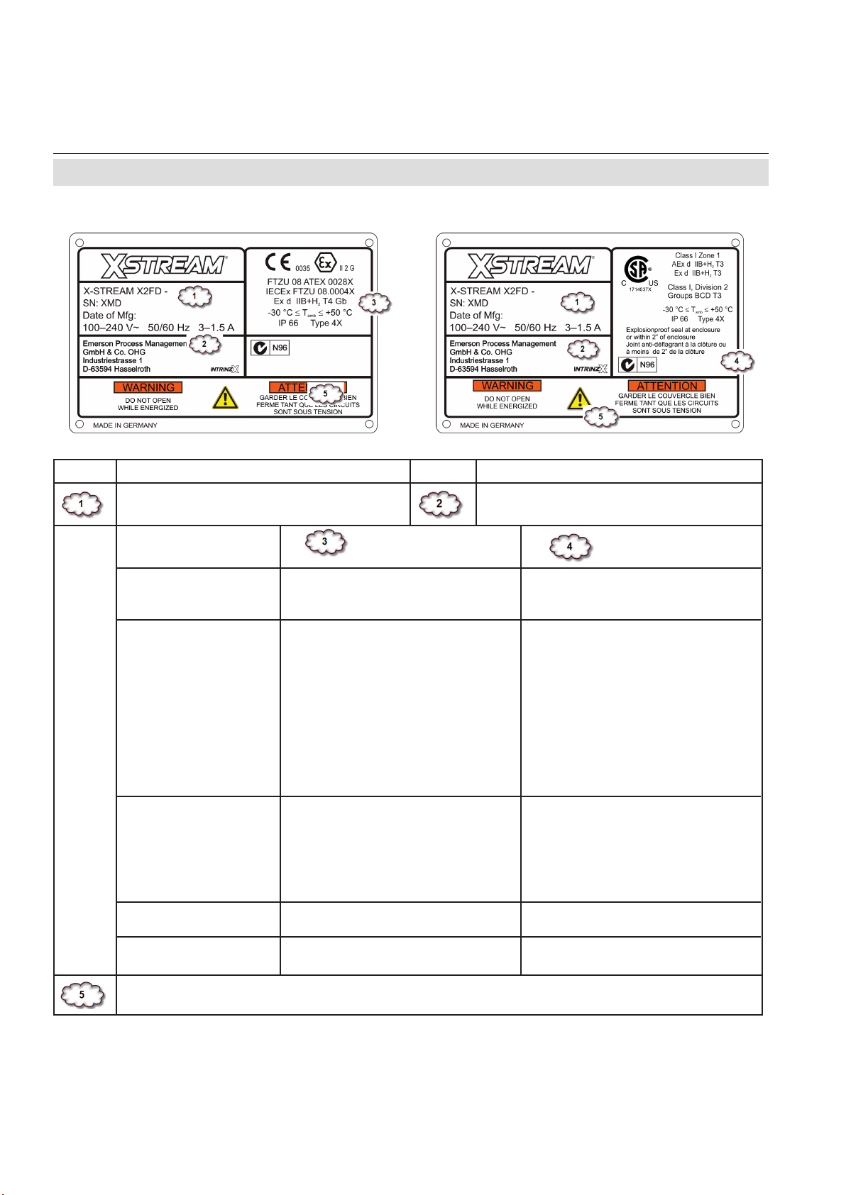
1.6 Nameplate Label
1.6 Nameplate Label
CSA-C/US versionATEX version
Area Description Area Description
The analyzer´s electrical data, manufac-
turing data and serial number
Manufacturer address
HASXMDE-IM-EX
03/2012
Certication Data
Area classication
Protection concepts
Additional Division
Marking, if applicable
Certicate numbers
Other
IECEx /
EU (ATEX)
II other than mines
2 Category 2 Equipm. (Zone 1)
G for explosive Gas atmosphere
Ex Explosion protected
d ameproof
IIB+H
Group II, Gas Group B
2
plus Hydrogen
T4 Temperature Class (135 °C)
Gb Equipment Protection Level
Ambient Temperature Range
T
amb
IP66, Type 4X Enclosure Rating
(outdoor use)
--
IECEx FTZU 08.0004X
FTZU 08 ATEX 0028 X
CE mark, number of Notied
Body for Quality assessment
North America (CSA)
Class I Flammable gases,
vapors or liquids
Zone 1 Zone 1 areas
AEx Explosion protected (US)
Ex Explosion protected (CAN)
d ameproof
IIB+H
Group II, Gas Group B
2
plus Hydrogen
T3 Temperature Class (200 °C)
Ambient Temperature Range
T
amb
IP66, Type 4X Enclosure Rating
(outdoor use)
Class I Flammable gases,
vapors or liquids
Division 2 Division 2 areas
Groups BCD all Gases, except
Acetylene
T3 Temperature Class (200 °C)
1714037X
Instruction note where to install
the explosion proof seal
Additional warning: Do not open the instrument while energized. Consult manual!
Fig. 1-3: Nameplate Label Details (exemplary)
Emerson Process Management GmbH & Co. OHG1-6
Page 23
Instruction Manual
HASXMDE-IM-EX
03/2012
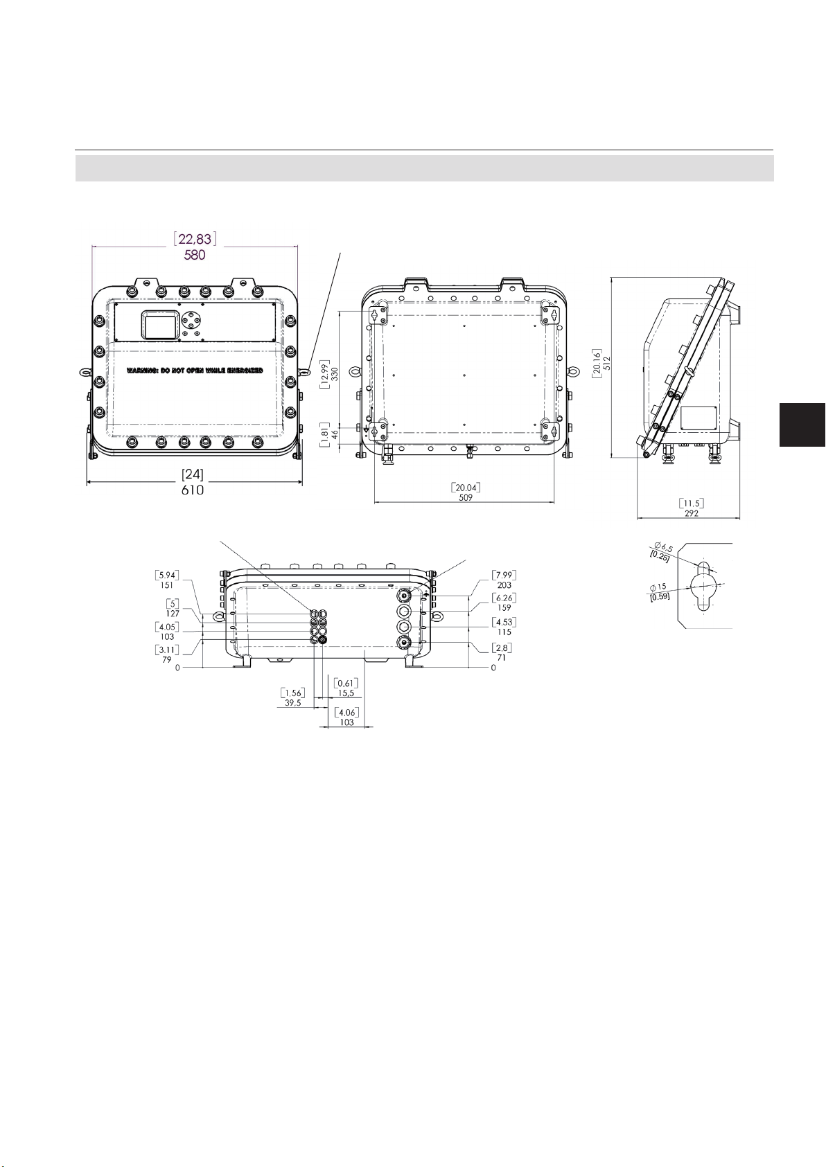
1.7 Technical Data
X-STREAM X2FD
1.7 Technical Data
Transport lugs to be removed after installation
Techn. Description
1
Flame arrestors with gas ttings
(enclosure threads: M18 x 1.5)
(enclosure threads; M20 x 1.5)
Cable inlets
Eyebolt detail
All dimensions in mm
[inches in brackets]
Fig. 1-4: Dimensions
Housing
Permissible operating ambient temperature range -30 °C to +50 °C (-22 F to +122 F)
Permissible storing ambient temperature range -30 °C to +70 °C (-22 F to +158 F)
Weight: approx. up to 63 kg (139 lbs)
(depending on analyzer conguration)
Protection class:
IP 66 (EN 60529) / Type 4X for outdoor in-
stallation (if applicable, see nameplate label !)
Analyzer must not be exposed to direct
sun light
Gas ttings: quantity: max. 8
specication: ame arrestors with ttings
connections: 6/4 mm or 1⁄4“, stainless steel
Emerson Process Management GmbH & Co. OHG 1-7
Page 24

Instruction Manual
X-STREAM X2FD
HASXMDE-IM-EX
1.7 Technical Data
Site of installation
Humidity (non condensing) < 90 % r. h. at +20 °C (68 F)
< 70 % r. h. at +40 °C (104 F)
Pollution degree 2
Installation category I I
Altitude 0 to 6560 ft (2000 m) above sea level
Sourrounding atmosphere Analyzers must not be operated in
corrosive atmosphere.
General Purpose Compliances
Electrical safety CAN / USA CSA-C/US, based on
CAN/CSA-C22.2 No. 61010-1-04 /
UL 61010-1, 2nd Edition
03/2012
Europe CE, based on EN 61010-1
Electromagnetic compatibility
Europe CE, based on EN 61326
other NAMUR
Power supply
Rated input voltage 100 - 240 V 50/60 Hz, wide range input
Power supply voltage uctuations are
not to exceed +/- 10 % of the nominal
supply voltage!
Input voltage range 85 - 264 V , 47 - 63 Hz
Nominal input current
standard 1.3 - 0.7 A max.
with temperature control 3 - 1.5 A max.
Emerson Process Management GmbH & Co. OHG1-8
Page 25

Instruction Manual
HASXMDE-IM-EX
03/2012
1.7 Technical Data
Interfaces, signal inputs / outputs
up to 4 analog outputs channel 4 (0) - 20 mA (RB < 500 Ω)
(Standard: 1 analog output per channel) optically isolated from each other and
from other electronic components;
user-congurable activation and
deactivation concentration levels;
support for NAMUR NE 43 operation
modes, congurable via keypad and
Modbus
4 relay outputs dry contacts,
max. load. 30 V; 1 A; 30 W resistive
X-STREAM X2FD
Techn. Description
1
Each output can be congured to one of the
following functions: NAMUR NE 107 status signal
“Failure”
“Out of specication”
“Function check”
Control signals for
external valve V1 ... V8,
external sample gas valve
external pump
Zoom status for analog outputs
Optional interfaces for all models
1 Modbus interface RS 485 (2 or 4 wire)
optional:
RS 232
Ethernet (RJ45 socket)
Digital inputs and outputs
“Maintenance request”
1 of 2 concentration limits per channel,
7 or 14 digital outputs max. 30 V, internally limited to 2.3 mA
HIGH: min. 4 V; LOW: max. 3 V
(common GND)
Emerson Process Management GmbH & Co. OHG 1-9
Page 26

Instruction Manual
X-STREAM X2FD
HASXMDE-IM-EX
03/2012
1.7 Technical Data
Each input can be congured to one of the
following functions: Open valve V1 ... V8
Open sample gas valve
Activate sample gas pump
Zero calibrate all channels
Span calibrate all channels
Zero and span calibrate all channels
Abort calibration
Zoom analog output 1
Zoom analog output 2
Zoom analog output 3
Zoom analog output 4
9 or 18 additional relay outputs dry contacts,
max. load. 30 V; 1 A; 30 W resistive
Each output can be congured to one of the
following functions: NAMUR NE 107 status signal
“Failure”
“Maintenance request”
“Out of specication”
“Function check”
1 of 2 concentration limits per channel,
Control signals for
external valve V1 ... V8,
external sample gas valve
external pump
Zoom status display for analog outputs
Emerson Process Management GmbH & Co. OHG1-10
Page 27

Instruction Manual
HASXMDE-IM-EX
03/2012
1.7 Technical Data
High sample and calibration gas pressures
X-STREAM X2FD
High gas pressure
care
Maximum ow 1,5 l/min.
Special conditions:
tected by suitable inline ame arrestors, designed
and approved for the applied higher gas
pressure. These inline ame arrestors need to be
installed outside the analyzer and in addition
to the ame arrestors provided by the analy
zer. A separate analyzer ame arrestor has
be installed, operating as a breathing device.
Connection of breathing device:
(exhaust) can be open to the ambience of the
analyzer, if the measured gas concentration is
below 25 % V-V LEL. Otherwise it must end
in a safe area.
Purging the housing with clean gas when e.g. measuring low concentrations
Maximum gas ow 2 l/min.
Permitted purge medium: Inert gas or air. Dry, clean, free of corrosives
or components containing solvents, and free
of components to be measured.
Its temperature must correspond to the am bient temperature of the analyzer, but be at
least within the range 20–35 °C (68–95 °F).
Above 1100 hPa to max. 1500 hPa (take
of the measurement principles limits!)
The gas paths need additionally to be pro-
to
The external output of the breathing device
Techn. Description
1
Special conditions:
ame arrestor. Another ame arrestor must
be installed, operating as a breathing device.
Connection of breathing device: The external output of the breathing device
(exhaust) can be open to the ambience of the
analyzer if inert gas is used as purge medium.
If air is used, the output must end in a safe
area, if the measured gas concentration is above
25 % V-V LEL.
Take care of special conditions for safe use (
Emerson Process Management GmbH & Co. OHG 1-11
The medium must be supplied via a separate
S-5 or 1-5 ) !
Page 28
Instruction Manual
X-STREAM X2FD
HASXMDE-IM-EX
1.7 Technical Data
Signal inputs and outputs
All signal cables are connected to internal
screw-type terminals (g. 1-5), except the optional RJ45 ethernet connector.
Cable cross-section: max. 1.5 mm2 (14 AWG),
end sleeves not required.
Cable entry via three IP 68 cable glands or conduits
03/2012
Permissible cable outer diameter:
see cable gland / conduit specication
Available signals: standard: Analog signal outputs
Relay status signals
Modbus interface (RS232; RS 485)
optional: Digital inputs/outputs
Modbus RJ45 ethernet connector
Detailed terminals conguration „Chapter 2
Installation“
Fig. 1-5: Signals terminals
Note!
Depending on the actual analyzer conguration
not all shown terminals may be provided!
Emerson Process Management GmbH & Co. OHG1-12
Page 29
Instruction Manual
HASXMDE-IM-EX
03/2012
X-STREAM X2FD
1.7 Technical Data
Power Connection
Connection via internal screw terminals near
cable entries, (g. 1-6).
Cross section: max. 4 mm2 (10 AWG), end sleeves not
required
Cable entry via 1 cable gland, classied IP 68 or suitable
conduit with metric-to-NPT adaptor
Permissible outer cable diameter for power
cord:
see cable gland / conduit specication
Power supply fuses
The power terminals integrate fuse holders.
Fuse ratings: AC 230 V / T 4 A / 5x20 mm
1 Power terminals with integrated
fuse holders
2 Protective earth terminal (PE)
3 Power cable entry
4 EMI power supply lter
4
Techn. Description
1
1
3
2
Fig. 1-6: Power terminals / fuse holders
Emerson Process Management GmbH & Co. OHG 1-13
Page 30

Instruction Manual
X-STREAM X2FD
HASXMDE-IM-EX
03/2012
1.8 Measurements Specications
1.8 Measurements Specications
Sample gas components and measuring ranges (standard congurations)
In total, more than 60 gases are detectable, so the following table gives an overview only.
Consult with Emerson for gases / congurations not listed.
Not all data is applicable to all analyzer variations. The sample gas(es) and measuring ranges
for your specic analyzer are given by the order acknowledgement and on the analyzer's name
plate label.
Acetone
Acetone
Acetylene C2H
Ammonia NH
Argon Ar TCD 0–50 % 0–100 %
Carbon dioxide CO
Carbon monoxide CO IR 0–10 ppm
Chlorine Cl
Ethane C2H
Ethanol
Ethylene C2H
Helium He TCD 0–10 % 0–100 %
Hexane
Hydrogen
Hydrogen Sulde H2S UV 0–2 % 0–10 %
Hydrogen Sulde H2S IR 0–10 % 0–100 %
Methane CH
Methanol
n–Butane C4H
Nitrogen dioxide
Nitrogen monoxide NO IR 0–100 ppm 0–100 %
Nitrous oxide N2O IR 0–100 ppm 0–100 %
Oxygen O
Oxygen O
Oxygen, Trace O
Propane C3H
Propylene C3H
Sulfur dioxide SO
Sulfur dioxide SO
Sulfur hexauoride SF
Toluene
Vinyl chloride C2H3Cl IR 0–1000 ppm 0–2 %
Water vapor
Water vapor, Trace
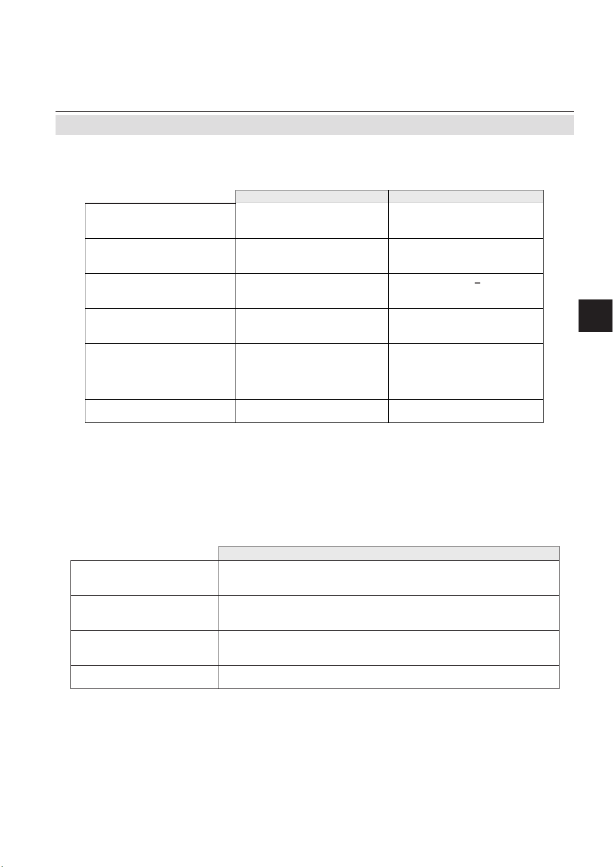
1
Dew point below ambient
temperature
Gas component Principle
1
1
1
1
4
1
1
1
CH3COCH
CH3COCH
2
3
2
2
6
C2H5OH IR 0–1000 ppm 0–10 %
4
C6H
14
H
2
4
CH3OH IR 0–1000 ppm 0–10 %
1
NO
C7H
10
2
2
2
2
8
6
2
2
6
8
H2O IR 0–1000 ppm 0–8 %
1
H2O capacitive 0–100 ppm 0–3000 ppm
2
Higher concentrations
decrease sensor lifetime
3
3
UV 0–400 ppm 0–3 %
IR 0–500 ppm 0–3 %
IR 0–3 % 0–100 %
IR 0–100 ppm 0–100 %
IR 0–5 ppm
UV 0–300 ppm 0–100 %
IR 0–1000 ppm 0–100 %
IR 0–400 ppm 0–100 %
IR 0–100 ppm 0–10 %
TCD 0–1 % 0–100 %
IR 0–100 ppm 0–100 %
IR 0–800 ppm 0–100 %
UV 0–25 ppm
electrochem. 0–5 % 0–25 %
paramagn. 0–1 % 0–100 %
electrochem. 0–10 ppm 0–10 000 ppm
IR 0–1000 ppm 0–100 %
IR 0–400 ppm 0–100 %
UV 0–25 ppm
IR 0–1 % 0–100 %
IR 0–5 ppm
UV 0–300 ppm 0–5 %
3
Special Specs
or Conditions
Lowest
Range
5
5
3
3
3
Daily zero calibration required for ranges below
lowest standard specs range
Standard Specs
(see Tab. 1-2 – 1-4)
Lowest
Range
0–50 ppm 0–100 %
0–50 ppm 0–100 %
0–50 ppm 0–10 %
0–50 ppm 0–1 %
0–20 ppm 0–2 %
4
Special "renery" application with 0–1% H2 in N2
available
Highest
Range
2
5
see Tab. 1-5
Tab. 1-1: Gas Components and Measuring Ranges, examples
Emerson Process Management GmbH & Co. OHG1-14
Page 31
Instruction Manual
HASXMDE-IM-EX
03/2012
1.8 Measurements Specications
Standard Performance Specications
X-STREAM X2FD
Detection limit (4 σ)
Linearity
1 4
Zero-point drift
Span (sensitivity) drift
Repeatability
1 4
1 4
1 4
1 4
Response time (t90) 3 4 s ≤ t90 ≤ 7 s
Permissible gas ow 0.2–1.5 l/min. 0.2–1.5 l/min. (+ 0.1 l/min)
Inuence of gas ow
Maximum gas pressure
Inuence of pressure
1 4
8 9
2
– At constant temperature ≤ 0.10 % per hPa ≤ 0.10 % per hPa
– With pressure compensation
Permissible ambient temperature
Inuence of temperature
(at constant pressure)
– On zero point ≤ 1 % per 10 K ≤ 1 % per 10 K
– On span (sensitivity) ≤ 5 % (0 to +50 °C / 32 to 122 °F) ≤ 1 % per 10 K
Thermostat control
Warm-up time
1
Related to full scale
2
Related to measuring value
3
From gas analyzer inlet at gas ow of 1.0 l/min
(electronic damping = 0 s)
4
Constant pressure and temperature
5
Dependent on integrated photometer bench
6 13
6
1 14
NDIR/UV/VIS Thermal Conductivity (TCD)
≤ 1 % ≤ 1 %
≤ 1 % ≤ 1 %
≤ 2 % per week ≤ 2 % per week
≤ 0.5 % per week ≤ 1 % per week
≤ 1 % ≤ 1 %
5
15 s ≤ t90 ≤ 30 s
≤ 0.5 % ≤ 1 %
12
6
Techn. Description
≤ 1500 hPa abs. (≤ 7 psig) ≤ 1500 hPa abs. (≤ 7 psig)
1
7
10
0 (-20) to +50 °C (32 (-4) to 122 °F) 0 (-20) to +50 °C (32 (-4) to 122 °F)
6
Depending on measuring range
7
Pressure sensor is required
8
Special conditions for > 1100 hPa abs. (1.5 psig)
9
Limited to atmospheric if internal sample pump
10
Temperatures below 0 °C (-4 °F) with thermostat
control only
≤ 0.01 % per hPa ≤ 0.01 % per hPa
none / 60 °C (140 °F) 5 none / 60 °C (140 °F) 11
15 to 50 minutes
5
approx. 50 minutes
Note! 1 psi = 68.95 hPa
11
Thermost. controlled sensor: 75 °C (167 °F)
12
Flow variation within ± 0.1 l/min
13
Optional thermostatically controlled box with
temperature 60 °C (140 °F)
14
Temperature variation: ≤ 10 K per hour
Tab. 1-2: NDIR/UV/VIS, TCD - Standard Measurement Performance Specications
Trace Moisture (tH2O)
Measurement range -100 to -10 °C dew point (0–3000 ppm)
Measurement accuracy ±2 °C dew point
Repeatability 0.5 °C dew point
Response time (t95) 5 min (dry to wet)
Operating humidity 0 to 100 % r.h.
Sensor operating temperature -40 to +60 °C
Temperature coefcient Temperature compensated across operating temperature range
Operating pressure
Flow rate
Depending on sequential measurement system, see analyzer specication
max. 1500 hPa abs / 7 psig
2
Depending on sequential measurement system, see analyzer specication
1
1
0.2 to 1.5 l/min
1
If installed in series to another measurement system, e. g. IR channel
2
Special conditions for > 1100 hPa abs. (1.5 psig)
Note! 1 psi = 68.95 hPa
Note! Do not calibrate, see special calibration notes in the X-STREAM X2 instruction manual!
Tab. 1-3: Trace Moisture - Standard Measurement Performance Specications
Emerson Process Management GmbH & Co. OHG 1-15
Page 32

Instruction Manual
X-STREAM X2FD
HASXMDE-IM-EX
03/2012
1.8 Measurements Specications
Oxygen Sensors
Detection limit (4 σ)
Linearity
1 4
Zero-point drift
Span (sensitivity) drift
Repeatability
Response time (t90)
1 4
1 4
1 4
1 4
3
Permissible gas ow 0.2–1.5 l/min
Inuence of gas ow 1
Maximum gas pressure
Inuence of pressure
4
7 8
2
– At constant temperature ≤ 0.10 % per hPa ≤ 0.10 % per hPa ≤ 0.10 % per hPa
– With pressure compensation
Permissible ambient temperature
Inuence of temperature
6
90(-20) to +50 °C (32 (4) to 122 °F) 5 to +45 °C (41 to 113 °F) 5 to +45 °C (41 to 113 °F)
1 13
(at constant pressure)
– On zero point ≤ 1 % per 10 K ≤ 1 % per 10 K ≤ 1 % per 10 K
– On span (sensitivity) ≤ 1 % per 10 K ≤ 1 % per 10 K ≤ 1 % per 10 K
Thermostat control 60 °C (140 °F) 12 none none
Warm-up time Approx. 50 minutes - Approx. 50 minutes
Paramagnetic (pO2) Electrochemical (eO2) Trace (tO2)
≤ 1 % ≤ 1 % ≤ 1 %
≤ 1 % ≤ 1 % ≤ 1 %
≤ 2 % per week ≤ 2 % per week ≤ 1 % per week
≤ 1 % per week ≤ 1 % per week ≤ 1 % per week
≤ 1 % ≤ 1 % ≤ 1 %
< 5 s approx. 12 s 20 to 80 s
11
0.2–1.5 l/min. 0.2–1.5 l/min.
11
≤ 2 %
≤ 1500 hPa abs. (≤ 7 psig)
14
≤ 1500 hPa abs. (≤ 7 psig) ≤ 1500 hPa abs. (≤ 7 psig)
≤ 2 % ≤ 2 %
≤ 0.01 % per hPa ≤ 0.01 % per hPa ≤ 0.01 % per hPa
Note! 1 psi = 68.95 hPa
10
5
5
1
Related to full scale
2
Related to measuring value
3
From gas analyzer inlet at gas ow of 1.0 l/min
(electronic damping = 0 s)
4
Constant pressure and temperature
5
Range 0–10…200 ppm: ≤ 5 % (5 to 45 °C /
41 to 113 °F)
6
Pressure sensor is required
7
Special conditions for > 1100 hPa abs. (1.5 psig)
8
Limited to atmospheric if internal sample pump
9
Temperatures below 0 °C (-4 °F) with thermostat
control only
10
Thermost. controlled sensor: 35 °C (95 °F)
11
Flow variation within ± 0.1 l/min
12
Optional thermostatically controlled sensor with
temperature 60 °C (140 °F)
13
Temperature variation: ≤ 10 K per hour
14
No sudden pressure surge allowed
Note! Take care of the tO2 sensor‘s documentation, providing important calibration instructions!
Tab. 1-4: Oxygen - Standard Measurement Performance Specications
Note 1!
Not all data listed are applicable to all analyzer versions (e.g. 60 °C thermostatically controlled
box is not available for electrochemical and trace oxygen).
Note 2!
For NDIR/UV/VIS measurements, take into account that
• sample gas may diffuse or be released by leakages into the analyzer enclosure
• if existent in the analyzer surroundings, the component to be measured may enter the enclosure.
Concentrations then may increase inside the enclosure. High concentrations of the component
to be measured inside the enclosure may inuence the measurement by unintended absorption,
which could cause drift of the measurement.
A remedy for this issue is to purge the housing with gas not containing the component of interest.
Emerson Process Management GmbH & Co. OHG1-16
Page 33

Instruction Manual
HASXMDE-IM-EX
03/2012
X-STREAM X2FD
1.8 Measurements Specications
Special Performance Specications for Gas Purity Measurements (ULCO & ULCO2)
0–10…< 50 ppm CO
0–5…< 50 ppm CO2
1 2
1 2 3
1 2
< 2 %
< 1 %
9
9
1 2 4
< 2 % resp. < 0.2 ppm
< 2 % resp. < 0.2 ppm
< 2 % resp. < 0.2 ppm 9
7
1 2
5
8
< 10 s
< 2%
≤ 0.01 % per hPa
9
9
Note! 1 psi = 68.95 hPa
Detection limit (4 σ)
Linearity
1 2
Zero-point drift
Span (sensitivity) drift
Repeatability
Response time (t90)
Permissible gas ow 0.2–1.5 l/min.
Inuence of gas ow
Maximum gas pressure 10 ≤ 1500 hPa abs. (≤ 7 psig)
Inuence of pressure
– At constant temperature ≤ 0.1 % per hPa
– With pressure compensation
Permissible ambient temperature +15 to +35 °C (59 to 95 °F) +5 to +40 °C (41 to 104 °F)
Inuence of temperature 6
(at constant pressure)
– On zero point < 2 % per 10 K resp. < 0.2 ppm per 10 K
– On span (sensitivity) < 2 % per 10 K resp. < 0.2 ppm per 10 K
Thermostat control none 60 °C (140 °F)
Techn. Description
1
1
Related to full scale
2
Constant pressure and temperature
3
Within 24 h; daily zero calibration requested
4
Within 24 h; daily span calibration recommended
5
Related to measuring value
6
Temperature variation: ≤ 10 K per hour
7
From gas analyzer inlet at gas ow of 1.0 l/min
8
Barometric pressure sensor is required
Tab. 1-5: Special Performance Specications for Gas Purity Measurements
9
Whichever value is higher
10
Limited to atmospheric if internal sample pump;
special conditions for > 1100 hPa abs. (1.5 psig)
Emerson Process Management GmbH & Co. OHG 1-17
Page 34

Instruction Manual
X-STREAM X2FD
HASXMDE-IM-EX
1.9 Vapor Recovery Application
1.9 Vapor Recovery Application (Simultaneous Measurement of CH4 and Non-CH4)
03/2012
This application is served by a special conguration of the X-STREAM X2FD ameproof
analyzer.
EXPLOSION HAZARD BY HOT COMPONENTS
Temperatures inside an analyzer for VAPOR RECOVERY applications exceed
the analyzer‘s temperature classication for hazardous areas!
Special conditions apply to handling this analyzer, consider the safety
instructions at the beginning of this manual and the special conditions for
safe use
(
1-5)
Consider the waiting time statement on the front door label before opening!
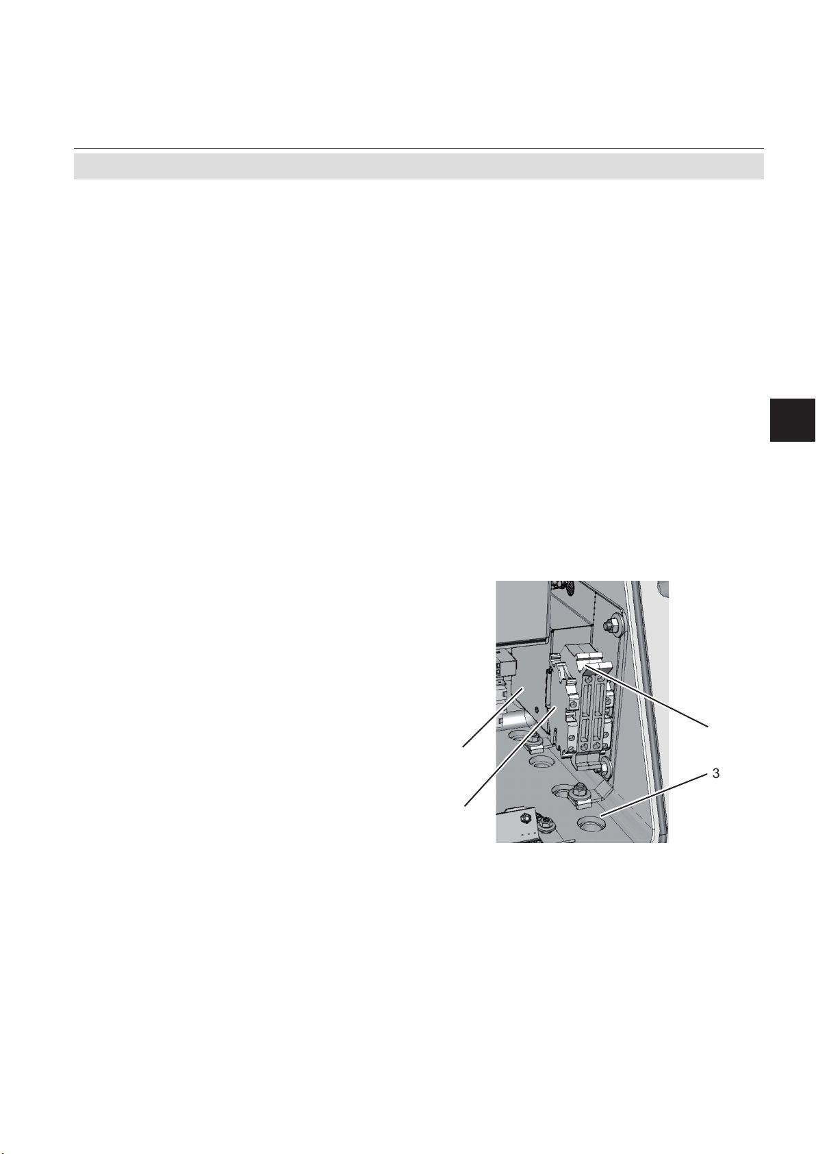
Principle of measurement
The sample gas is taken towards a converter.
At it‘s inlet the gas stream is divided into two:
one is directly fed to a non-CH4 measurement.
The other is supplied to a solenoid valve,
normally forwarding the gas to the converter.
Within the converter, hydrocarbons higher
than CH4 are converted into H2O and CO2.
The converter outlet is connected to a second
IR measurement system, analyzing the re-
maing amount of hydrocarbons (mainly CH4)
in the sample gas.
The conguration consists of a dual channel
IR measurement, connected to the inlet and
outlet of a converter. This converter is installed inside the X-STREAM analyzer and is
heated to about 280 °C (536 °F).
&+&+
CH2: non-CH
&+&+
CH1: CH
7
)
)$ )$ )$
9
Converter
&XWWHU
4
4
After switching power on, wait
about 50 min. for the converter
to reach its operating temperature before applying gases!
Fig. 1-7: Vapor Recovery Gas Flow Diagram
FA1: Analyzer‘s inlet ame arrestor
FA2...3: Analyzer‘s outlet ame arrestors
F1: Filter
T1: Throttle
V1: Valve
Emerson Process Management GmbH & Co. OHG1-18
Page 35

Instruction Manual
HASXMDE-IM-EX
03/2012
1.9 Vapor Recovery Application
Converter efciency
The measurement accuracy is highly depen-
dent on the converter efciency: If this is too
low, the converter material needs replacement.
To measure the converter efciency, one
has to compare the measurement values of
CH1 with and without having the gas owing
through the converter. This requires activating
the valve V1.
4 Maintenance section of this manual for
instructions about when and how to replace
the converter material.
X-STREAM X2FD
Techn. Description
1
Emerson Process Management GmbH & Co. OHG 1-19
Page 36

X-STREAM X2FD
Instruction Manual
HASXMDE-IM-EX
03/2012
Emerson Process Management GmbH & Co. OHG1-20
Page 37

Instruction Manual
HASXMDE-IM-EX
03/2012
X-STREAM X2FD
Chapter 2
Installation
On receipt, check the packaging and its contents thoroughly for damage.
Inform the carrier immediately of any damage to packaging or contents, and keep dama-
ged parts until clarication.
Store the instrument at a dry and clean place, considering the acceptable environmental conditions.
We recommend to keep the packaging available for future transportation, because only the ori-
ginal packaging ensures proper protection!
2.1 Scope of Supply
Installation
HAZARDS FROM MISSING INFORMATION
Compare the content of your package with the pictures below.
Call your local sales ofce if something is missing, and DO NOT continue
to install your analyzer, until all parts are at hand!
Analyzer
Allen key for ange screws
Metric-2-NPT adaptors for
CSA approved analyzers
(amount meets number of
non sealed threads).
2
USB
stick
Fig. 2-1: Scope of Supply
Emerson Process Management GmbH & Co. OHG 2-1
Instruction manuals:
- This manual addendum
- X-STREAM X2 instruction manual (on
USB stick)
Page 38

X-STREAM X2FD
2.2 Installing the Analyzer
POSSIBLE EXPLOSION HAZARD
Installing and wiring this instrument must comply with all relevant national
legislative requirements and regulations.
Consider all safety instructions within this on hand manual and all associated analyzer instruction manuals!
POSSIBLE EXPLOSION HAZARD
Instruction Manual
HASXMDE-IM-EX
03/2012
2 Installation
Installing this instrument requires opening the enclosure and working at
the open instrument. This is permitted only when both no hazardous atmosphere is present and the instrument and connected external circuitry are
de-energized!
Depending on the local regulation, this may require a competent hot work
supervisor to issue a hot work permit.
HEAVY INSTRUMENT
The analyzer model X-STREAM X2FD, to which this manual relates, intended
to be wall mounted and/or outdoor installed, weighs up to approx. 63 kg
(139 lbs), depending on included options!
Use two people and/or suitable tools for transportation and lifting these
instruments!
Take care to use anchors and bolts specied to be used for the weight of
the units!
Take care the wall or stand the unit is intended to be installed at is solid and
stable to hold the units!
Emerson Process Management GmbH & Co. OHG2-2
Page 39

Instruction Manual
HASXMDE-IM-EX
03/2012
Failure to follow this instruction and operating the analyzer without properly
threaded components may result in explosion hazards!
X-STREAM X2FD
2 Installation
EXPLOSION HAZARD
Installation
EXPLOSION HAZARD
Consider the permitted fastening torques when installing components to
the enclosure or closing the cover, as given in this section and on a label
at the instrument ( 2-6)!
2
Emerson Process Management GmbH & Co. OHG 2-3
Page 40

X-STREAM X2FD
2.2 Installation - Analyzer
Install the analyzer to a stand or a wall by
means of 4 eyebolts, provided at the instru-
ments rear side.
It is recommended to install the analyzer in an
upright (vertical) position; other orientations
may affect the measuring results.
Transport lugs to be removed after installation
Instruction Manual
HASXMDE-IM-EX
03/2012
IMPORTANT NOTE
When installing the analyzer
take care to have an area of min.
40 mm surrounding the ange
free of any solid components
not part of the instrument, to
ensure proper function of the
ange!
Flame arrestors with gas ttings
(enclosure threads: M18 x 1.5)
Fig. 2-2: Dimensions
Cable inlets
(enclosure threads; M20 x 1.5)
Eyebolt detail
All dimensions in mm
[inches in brackets]
Emerson Process Management GmbH & Co. OHG2-4
Page 41

Instruction Manual
HASXMDE-IM-EX
03/2012
2.3 Connecting Gas Lines
X-STREAM X2FD
2.3 Installation - Gas Lines
Gas inlets and outlets are protected by ame
arrestors, supporting stainless steel pipes of
either 3,18 mm (1⁄8“) or 6,35 mm (1⁄4“) outer
diameter (OD). The 1⁄4“ tting may optionally
be supplied with a clamping ring for 6 mm OD
pipes.
POSSIBLE EXPLOSION HAZARD
Take care not to damage the threats, this may void the instrument´s safety
and cause hazards!
Ensure unused entries remain sealed with approved plugs!
When thightening the tting, counterhold the
ame arrestor with a wrench placed at the
hexagon (items 5 of g. 2-3) next to the cap
nut (items 1, 4) to be tightened.
The instrument provides up to 8 gas inlets and
outlets, depending on the ordered conguration. Unused entries are closed by approved
plugs.
Installation
2
1
5
Always counterhold the ame
arrestor while thightening ttings; otherwise the ame arre-
stor may be damaged!
Maximum permitted fastening
torque: 40 Nm!
Fig. 2-3: Flame arrestor installed
into instrument enclosure
2
3
6
5
4
1: Gas tting 1⁄8“ (inside instrument) *
2: M18 male threat (inside enclosure wall)
3: O-ring (optional)
4: Gas tting 1⁄4“ or 1⁄8“ (outside instrument) *
5: Hexagon for counter holding while thightening
6: Hexagon for wrench when mounting into a M18 threat
7: O-ring shoulder
*) FA 01 with 1⁄4“ (outside instrument) and 1⁄8“ (inside)
FA 02 with 1⁄4“ at both ends
FA 03 with 1⁄8“ at both ends
Fig. 2-4: Flame arrestor elements,
exemplarly considering FA 01
)
7
)
Emerson Process Management GmbH & Co. OHG 2-5
Page 42
X-STREAM X2FD
Instruction Manual
HASXMDE-IM-EX
03/2012
2.3 Installation - Gas Lines
Gas ttings are accessible at the instrument‘s
outer bottom side.The number and assignment of gas inlet and outlet ttings depends
on the application and is given on a label attached to the analyzer‘s bottom side adjacent
For simple installation we recommend to
mark the gas lines according to the marking
on the analyzer label. This avoids confusion
during re-installation if the analyzer had to be
disconnected for whatever reason.
to the ttings.
2.3.1 Special Conditions
2.3.1.1 Purging the Housing with Clean Gas when e.g. Measuring Low Concentrations
POSSIBLE EXPLOSION HAZARD
Risk of internal overpressure under leakage conditions!
For the following option, take care to limit the total of purge gas ow and
highest ow of sample gas lines into the instrument to max. 2 l/min!
Take care of special conditions for safe use, and gas parameter specications
( S-5 and 1-10) !
The purge medium must be supplied via a
separate ame arrestor (purge gas inlet),
installed into the analyzer enclosure. Another
ame arrestor must be installed, operating as
a breathing device (purge gas outlet).
Connection of breathing device:
The external output of the breathing device
(exhaust) can be open to the ambience of the
analyzer, if inert gas is used as purge medium.
If air is used, the output must end in a safe
area, if the measured gas concentration is
above
25 % V/V LEL.
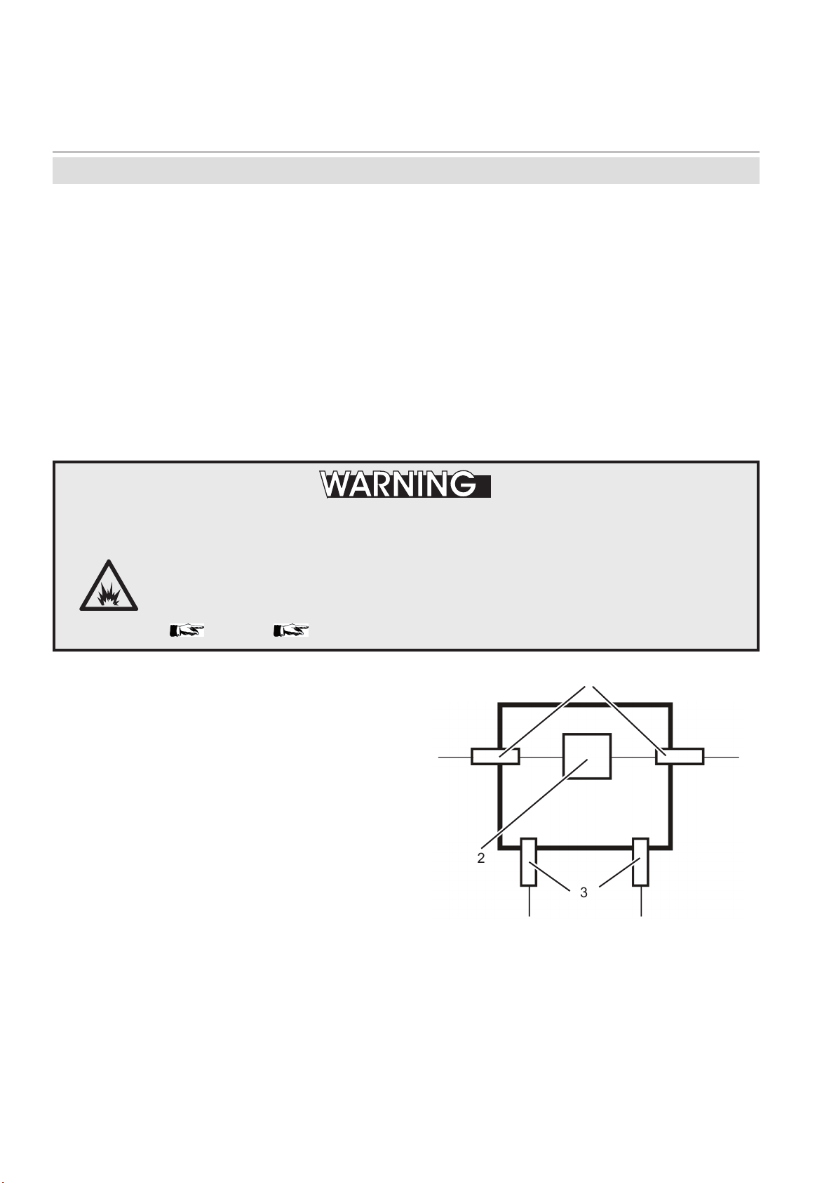
Fig. 2-5: Exemplary diagram for a single channel unit with purge option
1
2
3
1: Flame arrestors for gas path
2: Measuring system
3: Flame arrestors for purge gas in-/outlet
Emerson Process Management GmbH & Co. OHG2-6
Page 43

Instruction Manual
HASXMDE-IM-EX
03/2012
2.3 Installation - Gas Lines
2.3.1.2 High Sample and Calibration Gas Pressures
X-STREAM X2FD
The gas paths need additionally to be
protected by suitable external inline ame
arrestors, designed and approved for the
installation area and for the applied high-
er gas pressure (above 1100 hPa to max.
1500 hPa; see gas parameter specication
1-10). These inline ame arrestors need
to be installed outside the analyzer and in
addition to the ame arrestors provided by
the analyzer.
Note!
The external inline ame arrestors are not
subject of the analyzer certication and may
be provided by the customer, or optionally by
EMERSON PROCESS MANAGEMENT.
1: Flame arrestors for gas path
2: Measuring system
3: Flame arrestor as breathing device
4: External ame arrestors, approved
for higher pressure
2
A separate analyzer ame arrestor has to be
installed, operating as a breathing device,
limiting the internal pressure rise in case of
gas path leakage.
Connection of breathing device:
The external output of the breathing device (ex-
haust) may be open to the ambience of the analyzer, if the measured gas concentration is below
25 % V/V LEL. Otherwise it must end in a
safe area.
4
1
Installation
2
Fig. 2-6: Exemplary diagram for a single channel
instrument for high gas pressure
3
2.3.1.3 Fastening Torques for Enclosure Components
Consider the permitted fastening torques,
when installing components to the enclosure,
as given on a label at the instrument!
Fig. 2-7: Label with fastening torques,
installed at the instrument
Emerson Process Management GmbH & Co. OHG 2-7
Page 44

X-STREAM X2FD
2.3.2 Gas Conditioning
Instruction Manual
HASXMDE-IM-EX
03/2012
2.3 Installation - Gas Lines
In order to ensure trouble-free operation, special attention must be paid to the preparation
of the gases:
All gases must be conditioned
before supplying to the analyzer,
to be
• dry,
• free of dust and
• free of any aggressive com-
ponents which may damage
the gas lines (e.g. by corrosion or solvents) .
Case purge option
The purge medium (e.g. to minimize CO
interference or for enhanced safety when
measuring corrosive or poisonous gases)
• must be dry, clean and free of corrosives or components containing solvents.
• has to be free of components to be
measured, to minimize cross interferences.
Its temperature must correspond to the ambient temperature of the analyzer, but be at
least within the range 20…35 °C (68…95 °F).
For safety reasons, consider section 2.3.1
when making use of this option!
Pressure and gas ow must remain within
the values given in the „Measurement
Specications“ section within this manual.
If moisture cannot be avoided, it is necessary
to ensure that the dew point of the gases is at
least 10 °C (18 °F) below the ambient temperature to avoid condensate in the gas lines.
Hints for selected gases
• Calibration gases for CO and NO need
to be moistured by supplying them via a
cooler.
Open reference option
I
2
n some cases, the measuring cell has an open
reference side, to be supplied with nitrogen.
This nitrogen
• at least should be of quality 5.0, which
means nitrogen of purity ≥ 99.999 %.
If such gas is not available, the substitute
• must be dry, clean and free of corrosives or components containing solvents.
• has to be free of components to be
measured, to minimize cross interferences.
In any case, the gas temperature must correspond to the ambient temperature of the
analyzer, but at least be within the range
20…35 °C (68…95 °F).
Pressure and gas ow must remain within
the values given in the „Measurement
Specications“ section within this manual.
Perform a calibration each time
the source of this gas (e. g.
bottle) has changed!
Emerson Process Management GmbH & Co. OHG2-8
Page 45

Instruction Manual
HASXMDE-IM-EX
03/2012
2.4 Electrical Installation
Installation and connecting power and signal cables are subject to qualied
personnel only, taking into account all applicable standards and legislative
requirements!
X-STREAM X2FD
2.4 Installation - Electrical
ELECTRICAL SHOCK HAZARD
Failure to follow may cause warranty invalidation, property damage and/or
personal injury or death!
Installation of these instruments is subject to qualied personnel only,
familiar with the resulting potential risks! Instruments providing screw
terminals for electrical connections may require working near live part!
X-STREAM X2FD gas analyzers do not provide a power switch!
A power switch or circuit breaker (complying with IEC 60947-1/-3) has to be
provided in the building installation. This switch has to be installed near
by analyzer, must be easily operator accessible and has to be assigned as
disconnector for the analyzer.
Disconnect instruments with screw terminals from power when working at
power terminals (pull power plug or operate power switch/ circuit breaker
in building installation)!
The analyzers provide a protective earth terminal. To prevent electrical
shock hazards the instruments must be connected to a protective earth.
Therefore the instruments must be connected to power by using a three
wire power cable with earth conductor!
Any interruption of the earth connector inside or outside the instrument
or disconnecting the earth terminal may cause potential electrical shock
hazzard!
Installation
2
The analyzers do not provide a power switch and are operable when connected to power.
Emerson Process Management GmbH & Co. OHG 2-9
Page 46

X-STREAM X2FD
Do not open instrument when energized.
Ensure that external circuitry is disconnected or de-energized before
opening the instrument.
All cables (power and signal) must end (be connected) in either a safe (nonhazardous) area or in a protecting enclosure (e.g. Ex e junction box)!
SELECT THE CORRECT TYPE OF CABLE ENTRY
Instruction Manual
HASXMDE-IM-EX
03/2012
2.4 Installation - Electrical
POSSIBLE EXPLOSION HAZARD
Before starting to install the analyzer, verify what type of cable entry is required at your
site of installation:
X-STREAM X2FD gas analyzers may be equipped with cable glands (regulated e.g. for
installations covered by ATEX) or may be installed with conduits (e.g. in North-America).
INSTALLATION USING CONDUITS
X-STREAM X2FD analyzers provide metric threads for installing cable
entries. Installing conduits requires using metric-to-NPT adaptors!
To stay compliant with the North-American certication use only ameproof
certied adaptors, e.g. the following type:
Redapt AD-U series, stainless steel with captive o-ring seals,
size male M20 x 1.5 to female 3/4-NPT or 1/2-NPT.
Select a type of conduit according the local code, suitable for above
mentioned adaptors and the site of installation.
During installation follow the instructions provided by the manufacturer
of the conduits!
Unused entries must be provided with ameproof plugs!
Emerson Process Management GmbH & Co. OHG2-10
Page 47
Instruction Manual
HASXMDE-IM-EX
03/2012
X-STREAM Flameproof analyzers are shipped without certied cable glands.
Cable glands have to be selected while preparing the installation according
all applicable standards, e. g. EN 60079-14 or IEC 60079-14.
Use only cables as specied in the cable glands installation instruction,
and carefully follow the original manufacturer‘s installation instructions,
accompanying the cable glands!
X-STREAM X2FD
2.4 Installation - Electrical
INSTALLATION USING CABLE GLANDS
Installation
2
The next page shows
• the English installation instructions for type
AD-U adapters, reprinted with the permission of
Redapt Ltd
Note!
See the documentation delivered together
with your analyzer for an original version of
the cable gland or adapter installation instructions, whatever is applicable !
Emerson Process Management GmbH & Co. OHG 2-11
Page 48

X-STREAM X2FD
2.4 Installation - Electrical
Type AD-U adapter installation instructions
Instruction Manual
HASXMDE-IM-EX
03/2012
Emerson Process Management GmbH & Co. OHG2-12
Page 49

Instruction Manual
HASXMDE-IM-EX
03/2012
2.4 Installation - Electrical
ATEX approved analyzers provide 4 cable
entries (M20 x 1.5) and are shipped with a
set of 4 plugs.
Owner of such analyzers are responsible to
provide suitable cable glands according all ap-e suitable cable glands according all applicable standards (e. g. IEC/EN 60079-14).
See maintenance section of this manual for
recommended cable glands.
X-STREAM X2FD
Unused entries during installation have to be
provided with plugs!
Installation under CSA certication requires
the use of approved conduits and suitable
metric-to-NPT adaptors. .
Both plugs and cable entries must be installed
properly and xed by applying the prescribed
torque.
The instrument provides internal screw termi-
nals for connecting power and signal cables.
This requires opening the instrument during
installation:
Installation
2
1 42 35
1 Terminals for signal cables
2 Power EMI lter
3 4 cable entries for power and signal cables
4 Power terminals with integrated fuses
5 Ethernet connector (option)
Fig. 2-8: Allocation of terminals
• Unsrew the 20 screws located on the
enclosure ange.
• Flap down the cover part to gain access
to the analyzer inside.
Inside the enclosure, keep all cables as short
as possible to prevent from interferences.
Emerson Process Management GmbH & Co. OHG 2-13
Page 50

X-STREAM X2FD
Instruction Manual
HASXMDE-IM-EX
03/2012
2.4 Installation - Electrical
Installation with conduits
Ensure all required parts are available:
Adaptors, suitable conduits, compound and
plugs for not used entries (see accessory kit).
Install the required number of adaptors into
the related cable entries:The 3 rear entries
are reserved for signal cables, the rst one is
for the power cord.
Tightening torque:
max. 354 in.lb / 40 Nm!
Ensure the explosionproof seal is placed
at the analyzer enclosure or within 2“ from
enclosure.
All cables need to be fed properly through
conduits when entering the instrument and
connected to the terminals ( warning
notes, page 2-8).
To seal the cable entries proceed according to
the installation instruction given in the related
conduits manufacturer documentation.
Keep the original manufacturer‘s
documentation available for future reference!
Seal unused entries utilizing the ameproof
certied plugs.
Installation with cable glands
Ensure all required parts are available:
Cable glands and plugs for not used entries.
Verify the provided cable gland is designed
for your type of cable (e. g. armoured, non-;
diameter), see marking on the cable gland.
Install the required number of cable glands
according the manufacturers instruction into
the related cable entry:The 3 rear entries are
reserved for signal cables, the rst one is for
the power cord.
Tightening torque:
max. 354 in.lb / 40 Nm!
All cables need to be fed properly through the
cable glands when entering the instrument
and connected to the terminals ( warning
notes, page 2-8).
To seal the cable entries proceed according to
the installation instruction given in the related
cable glands manufacturer documentation.
Keep the original manufacturer‘s
documentation available for future reference!
Seal unused entries utilizing the ameproof
certied plugs.
Preparation of signal cables
All signal cables are to be connected via
screw terminals, except the optional ethernet
connector, located inside the analyzer.
Supported wire cross sections: 0,14 to 1,5 mm2 (26 to 15 AWG) ,
no need to use wire end sleeves
Cable skinning length: 5 mm (0.2 inch)
Screw thread: M 2
Tightening torque, min: 0,25 Nm (2.3 in.lb)
Emerson Process Management GmbH & Co. OHG2-14
Page 51

Instruction Manual
HASXMDE-IM-EX
03/2012
X-STREAM X2FD
2.4 Installation - Electrical
Analog Outputs
Relay Outputs 1 - 4
Terminals for analog signals and relais outputs
1 - 4 are located at the leftmost terminal module
(terminal block X1; g. 2-5).
Analog outputs specication: 4 (0) - 20 mA; burden: RB ≤ 500 Ω
Specication of relay outputs 1-4: Dry
relay change-over contacts
can be used as NO or NC.
Electrical specication: max. 30 VDC, 1 A, 30 W
Note!
Take care of the special installation instructions in section 4.5 of the X-STREAM gas
analyzer series manual!
Pin Signal
P2.1 Channel 1, (+) 4 (0) - 20 mA
P2.2 Channel 1, GND
P2.3 Channel 2, (+) 4 (0) - 20 mA
P2.4 Channel 2, GND
P2.5 Channel 3, (+) 4 (0) - 20 mA
P2.6 Channel 3, GND
P2.7 Channel 4, (+) 4 (0) - 20 mA
P2.8 Channel 4, GND
P2.9 not used
P2.10 not used
P2.11 not used
P2.12 not used
P3.1 not used
P3.2 not used
P3.3 Output 1 (Failure), NC
P3.4 Output 1 (Failure), NO
P3.5 Output 1 (Failure), COM
P3.6 Output 2 (Maintenance Request), NC
P3.7 Output 2 (Maintenance Request), NO
P3.8 Output 2 (Maintenance Request), COM
P3.9 Output 3 (Out of Spec), NC
P3.10 Output 3 (Out of Spec), NO
P3.11 Output 3 (Out of Spec), COM
P3.12 Output 4 (Function check), NC
P4.1 Output 4 (Function check), NO
P4.2 Output 4 (Function check), COM
P4.3 not used
P4.4
P4.5
P4.6
P4.7
P4.8
P4.9
P4.10
P4.11
P4.12
Installation
2
Serial Interface
*)
Relay Outputs
**)
**)
Conguration of relay output termi-
Conguration of relay output termi-
nals as per standard factory setting
nals as per standard factory setting
(NAMUR status signals)
(NAMUR status signals)
**)
Analog Outputs
Fig. 2-9: Terminals block X1 - analog signals and relay outputs 1-4
Emerson Process Management GmbH & Co. OHG 2-15
Page 52

X-STREAM X2FD
Modbus Interface
Instruction Manual
HASXMDE-IM-EX
03/2012
2.4 Installation - Electrical
Specication and interface control:
Analyzer instruction manual, chapter 9
P3.12 Output 4 (Function check), NC
P4.1 Output 4 (Function check), NO
P4.2 Output 4 (Function check), COM
P4.3 not used
P4.4
P4.5
P4.6
P4.7
P4.8
P4.9
P4.10
P4.11
P4.12
P3.3 Output 1 (Failure), NC
P3.4 Output 1 (Failure), NO
P3.5 Output 1 (Failure), COM
P3.6 Output 2 (Maintenance Request), NC
P3.7 Output 2 (Maintenance Request), NO
P3.8 Output 2 (Maintenance Request), COM
P3.9 Output 3 (Out of Spec), NC
P3.10 Output 3 (Out of Spec), NO
P3.11 Output 3 (Out of Spec), COM
The 9 terminals on the left (28 - 36) of the
strip next to the power connections carry the
Modbus interface signals.
Pin Signal
P2.1 Channel 1, (+) 4 (0) - 20 mA
P2.2 Channel 1, GND
P2.3 Channel 2, (+) 4 (0) - 20 mA
P2.4 Channel 2, GND
P2.5 Channel 3, (+) 4 (0) - 20 mA
P2.6 Channel 3, GND
P2.7 Channel 4, (+) 4 (0) - 20 mA
P2.8 Channel 4, GND
P2.9 not used
P2.10 not used
P2.11 not used
P2.12 not used
P3.1 not used
P3.2 not used
Serial Interface
*)
See table below
*)
Relay Outputs
Assignment of serial interface terminals
Termi-
nal
P4.4 Common Common Common
P4.5 not used not used RXD
P4.6 not used not used TXD
P4.7 not used RXD1 not used
P4.8 D1 TXD1 Common
P4.9 not used not used not used
P4.10 not used not used not used
P4.11 not used RXD0 not used
P4.12 D0 TXD0 not used
Fig. 2-10: Terminals block X1 - Modbus interface
MOD 485/
2 wire
MOD 485/
4 wire
RS 232
**)
Analog Outputs
Note!
Take care of the special installation instructions in section 4.5 of the
X-STREAM gas analyzer series instruction manual!
Note 2!
X-STREAM analyzers are to be considered a DTE (Data Terminal Equipment).
Emerson Process Management GmbH & Co. OHG2-16
Page 53

Instruction Manual
HASXMDE-IM-EX
03/2012
2.4 Installation - Electrical
Optional Modbus RJ45 connection
If tted, the optional RJ45 connection is located on an electronics board in the card cage
section of the unit (g. 2-4.
To install this connection, a cable must be
fed through the cable entry without a con-
nector.
The connector can be wired on when the free
end has been fed into the instrument:
We recommend the VARIOSUB RJ45 QUICKON connector (PHOENIX CONTACT), which
is supplied with the unit and requires no spe-
cial tools. Wiring instructions can be found
in the separate manual supplied with the
connector.
X-STREAM X2FD
Note!
Take care that the Modbus terminals
2-16) are still installed but not connected!
(
Installation
2
Pin 1 Pin 8
Pin no.
1 TX+
2 TX3 RX+
6 RX-
other not used
Fig. 2-11: Modbus Interface - Ethernet connector
Emerson Process Management GmbH & Co. OHG 2-17
Signal
Page 54

Instruction Manual
X-STREAM X2FD
HASXMDE-IM-EX
03/2012
2.4 Installation - Electrical
Digital inputs
Quantity: 7 (1 terminal block) or
14 (2 terminal blocks)
Electrical specication: max. 30 V , internally limited to 2.3 mA
H Signal: min. 4 V;
L Signal: max. 3 V
common ground (GND), electrically
isolated from chassis earth
Digital outputs
Quantity: 9 (1 terminal block) or
18 (2 terminal blocks), dry change-over
relay contacts, can be used as NO or NC
Electrical specication: max. 30 VDC, 1 A, 30 W
Notes!
Depending on conguration, an analyzer can
be tted with up to two of these terminal blocks
(the unit will then feature 14 digital inputs and
18 digital outputs). To aid identication, the
sockets are labelled X4.1 and X4.2.
P4.1 Output 6, NC
P4.2 Output 6, NO
P4.3 Output 6, COM
P4.4 Output 7, NC
P4.5 Output 7, NO
P4.6 Output 7, COM
P4.7 Output 8, NC
P4.8 Output 8, NO
P4.9 Output 8, COM
P4.10 Output 9, NC
P4.11 Output 9, NO
P4.12 Output 9, COM
P2.1 Output 10, NC
P2.2 Output 10, NO
P2.3 Output 10, COM
P2.4 Output 11, NC
P2.5 Output 11, NO
P2.6 Output 11, COM
P2.6 Output 12, NC
P2.8 Output 12, NO
P2.9 Output 12, COM
P2.10 Output 13, NC
P2.11 Output 13, NO
P2.12 Output 13, COM
P3.8 GND for Inputs 1-7
P3.9 not used
P3.10 Output 5, NC
P3.11 Output 5, NO
P3.12 Output 5, COM
Note!
Take care of the special installation instructions in section 4.5 of the X-STREAM gas
analyzer series manual!
P4
Pin Signal
P3.1 Input 1
P3.2 Input 2
P3.3 Input 3
P3.4 Input 4
P3.5 Input 5
P3.6 Input 6
P3.7 Input 7
Note!
The conguration illustrated here is that of the rst
adapter, labelled X4.1.
Inputs 8-14 and outputs
14-22, if available, are on
the second adapter X4.2,
see label above).
Digital InputsDigital Outputs
Fig. 2-12: Terminal blocks X4.1 and X4.2 - Digital inputs and outputs
Emerson Process Management GmbH & Co. OHG2-18
Page 55

Instruction Manual
HASXMDE-IM-EX
03/2012
X-STREAM X2FD
2.4 Installation - Electrical
Connecting the power cord
The power cord is connected to screw-type terminals located inside the housing.
Electrical Connections
Power terminals
Schraubklemmen mit integrierten Sicherungshaltern
max. 4 mm²
Supported wire cross sections
0.2 to 4 mm2 (24 to 12 AWG) no need to use wire end sleeves
Cable skinning length 8 mm (0.315 inch);
Tightening torque, min . 0.5 Nm (4.4 in.lb)
Power Inlet Fuses
Data AC 230 V / T 4 A / 5x20 mm
Cable Inlets
Variations
Outer cable diameter (cable
glands)
Cable glandes, IP 68, or
Conduits with adaptors (metric-2-NPT)
depending on cable gland
To install the cable proceed according to the
installation instructions for either conduits or
cable glands, given on page 2-11.
Insert the power cord through the foremost
L= Line
N=Neutral
PE=Protective Earth
entry, strip the outer insulation, skin and
connect the conductors to the terminals (a
descriptive label is attached nearby the termi-
Power cord entry
nals), by inserting them from the bottom sides.
Installation
2
L
N
PE
Fig. 2-13: Power terminals
ELECTRICAL SHOCK HAZARD
Verify the power supply at installation site meets the specication given on
the analyzer´s nameplate label, before installing the instrument!
Verify power cables are disconnected and/or instrument is de-energized
prior to working at the terminals!
Verify the power cord is layed with a distance of at least 1 cm (0.5“) to any
signal cable to ensure proper insulation from signal circuits!
Emerson Process Management GmbH & Co. OHG 2-19
Page 56

X-STREAM X2FD
2.4 Installation - Electrical
Connecting an optional equipotential
bonding conductor
The X-STREAM X2FD enclosure provides
an additional terminal for connecting an equi-
potential conductor, located at the base part
ange´s rear side (see g. 2-14), near the
nameplate label.
Screw thread: M5 x 10 mm
Conductor cross section: min. 4 mm²
The installation has to comply with sound
engineering practice (see example to the
right). Take care of contact corrosion due to
the aluminum cast enclosure.
Instruction Manual
HASXMDE-IM-EX
03/2012
Fig. 2-14: Equipotential bonding conductor terminal
1
1 Lock washer
2 Ring terminal
3 Flat washer
2
4 Lock washer
5 Screw M5
4
3
5
Emerson Process Management GmbH & Co. OHG2-20
Page 57

Instruction Manual
HASXMDE-IM-EX
03/2012
Before completing the electrical connection of the instrument, verify cables
are inserted and connected in correct manner!
Ensure the earthing conductor (protective earth; PE) is connected!
X-STREAM X2FD
2.4 Installation - Electrical
ELECTRICAL SHOCK HAZARD
Installation
After all connections are established in the
specied manner, and veried,
• x the cables according to the installation
instruction given in the cable glands / con-
duits manufacturer documentation.
• All cable entries must be sealed by means of either Ex d approved cable glands,
conduits or sealing plugs.
• Install the analyzer´s cover by means of
ALL 20 screws!
EXPLOSION HAZARD
Do NOT operate the instrument with doors, sealing plugs or covers open!
This is permitted only when no hazardous atmosphere is present!
Depending on the local regulation, this may require a competent hot work
supervisor to issue a hot work permit.
2
Tightening torque:
25 Nm (221 in.lb)
Use ALL 20 screws to x the cover! Violation may cause an explosion!
Emerson Process Management GmbH & Co. OHG 2-21
Page 58

X-STREAM X2FD
Instruction Manual
HASXMDE-IM-EX
03/2012
Emerson Process Management GmbH & Co. OHG2-22
Page 59

Instruction Manual
HASXMDE-IM-EX
03/2012
Ensure all covers, plugs and housing parts are in place and secured properly
before supplying power and signal voltages!
Ensure all requirements given by the clarication sheet for performing
gas analysis within a ameproof enclosure are considered BEFORE
supplying gases ( page S-10)!
The sheet also gives instructions for the sequence of supply-ing gases
during process and analyzer startup .
X-STREAM X2FD
Chapter 3
Startup
EXPLOSION HAZARD
Startup
3.1 Final Check
Ensure that the analyzer has been installed
according to the descriptions in chapter 2,
and that all covers and doors are closed and
fastened.
OPERATION AT LOW TEMPERATURES
When operating an instrument at temperatures below 0 °C (32 °F), do
NOT apply gas nor operate the internal pump before the warmup time has
elapsed!
Violation may result in condensation inside the gas paths or damaged
pump diaphragm!
Consider the related instructions in the X-STREAM X2 series manual!
3
Emerson Process Management GmbH & Co. OHG 3-1
Page 60

X-STREAM X2FD
3.2 Leak Test
3.2 Performing a Leak Test
Before starting up the instrument, it appears
to be appropriate to perform a leak test, thus
ensuring the gas path system does not have
leaks, and to achieve best and proper measuring results.
The following procedure describes how to perform a leak test with focus on the instrument.
The gas path system should be leak tested
at least on a bimonthly basis and after main-
tenance, replacement or repair of gas path
parts.
Note!
It is recommended to include external equip-
ment (e.g. cooler, dust lters, etc.) into a leak
test!
Instruction Manual
HASXMDE-IM-EX
03/2012
HAZARD FROM GASES
Before opening gas paths
they must be purged with
ambient air or neutral
gas (N2) to avoid hazards
caused by toxic, ammable,
explosive or harmful to
health sample gas components!
Required tools
• U-turn manometer for max. 1.45 psi
(100 mbar)
• Stop valve
Procedure
• Connect the water lled u-turn manome-
ter to the analyzer‘s sample gas output
(disconnect external gas lines).
• Install the stop valve between gas input
tting and a Nitrogen (N2) supply.
• Open the stop valve until the internal
gas path is under pressure of approx.
0.725 psi/50 mbar (corresponding to 19.7
inch/500 mm water column)
• Close the stop valve. After a short time
for the water to balance, the water level
must not change over a time period of
approx. 5 minutes!
Analyzer
overpressure
stop
valve
Water
Fig. 3-1: Leak Testing with U-turn Manometer
approx.
0.725 psi /
50 mbar
Max. pressure 7.25 psig
(500 mbar)!
Multi channel instruments:
Analyzers with parallel tubing
require separate leak tests for
each gas path !
Emerson Process Management GmbH & Co. OHG3-2
Page 61

Instruction Manual
HASXMDE-IM-EX
03/2012
3.3 Switching On
X-STREAM X2FD
3.3 Switching On
Once the unit has been unpacked and installed, we recommend to rst check the
settings, and if necessary adjust them to the
user’s needs. e.g:
• What hardware is installed?
• Is the unit configured to your needs
(alarms, inputs, outputs, etc.)
EXPLOSION HAZARD
Before applying power and signals:
• Verify for proper installation
• Verify that all covers and plugs are properly installed and in place!
In order for the information in this chapter
to be of any relevance, the unit must have
been installed according to the instructions
in chapter 2.
The following pages describe how to navigate
through the menus and what is to be observed
when conguring the unit. For the rst startup
after installation, follow the step-by-step in-
structions for navigating the menus, allowing
you to familiarise yourself with the unit and its
software, and if necessary adjust the settings
to your needs.
Startup
3
• Verify that all gas connections are tight.
Violation may result in explosion, personal injury or death!
EXPLOSION HAZARD BY HOT COMPONENTS
Temperatures inside an analyzer for VAPOR RECOVERY applications exceed
the analyzer‘s temperature classication for hazardous areas!
Special conditions apply to handling and operating this analyzer, consider
the safety instructions at the beginning of this manual!
Switch on the analyzer by applying power.
Emerson Process Management GmbH & Co. OHG 3-3
Page 62

X-STREAM X2FD
3.4 Symbols used
3.4 Symbols used
In the following sections, the symbols and
typographical conventions described below
are used to describe the software menus and
navigation.
Instruction Manual
HASXMDE-IM-EX
03/2012
Symbols and conventions used
lowing sections
Symbol Meaning
Within descriptions of procedures
Setup..
Setup..
Analog outputs..
Analog outputs..
Output1 (2...4)
Zero calibration..
Span calibration..
Adv. Calibration..
Apply gas..
Menu title
Parent (Setup) and current
Menu (Analog outputs)
As an example, the menu
for Output1 is displayed;
the menus for outputs 2 to
4 are identical
Display
Note!
Menus or lines on a grey
background are optional or
context-dependent, and are
not always displayed
Access levels:
in the fol-
Convention Meaning
Within descriptions
(Menu title)
6.2.2, page 6-12
CONTROL - ZOOM..
„Valves“ Parameter name
Never, 1 min Selectable values
0 ... 2000 Range of values
For a detailed description
of this Menü, see section
6.2.2 on page 6-12
Navigate from the main
menu via the CONTROL
menu to the ZOOM.. menu
Access level 1
(user)
Access level 2
(expert)
Access level 3
(administrator)
Access level 4
(service level)
Emerson Process Management GmbH & Co. OHG3-4
Page 63
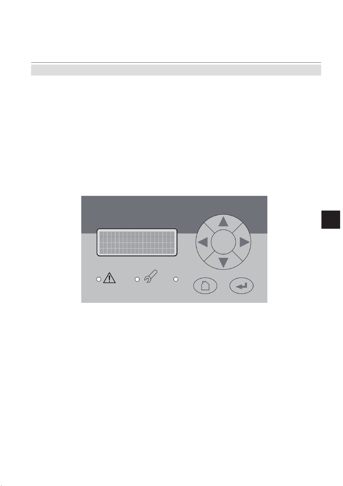
Instruction Manual
HASXMDE-IM-EX
03/2012
3.5 The user interface
X-STREAM X2FD
3.5 The user interface
All X-STREAM gas analyzers have an alphanumeric display with four lines of 20
characters to display measuring and status
information and the easy-to-use menu-based
user interface for entering parameters. For
ease of understanding, the user can at any
time select one of three languages stored in
the unit (currently available: English, French,
German, Italian and Spanish in various com-
binations).
Units are operated using six keys on the front
panel.
Three LEDs on the front panel enable the
operating status to be recognised instantly.
Startup
3
Fig. 3-2: Front Panel
Emerson Process Management GmbH & Co. OHG 3-5
Page 64

X-STREAM X2FD
3.5.1 Display
3.5.2 Status LED
Instruction Manual
HASXMDE-IM-EX
03/2012
3.5 The user interface
The display has 4x20 characters, either liquid
crystal or vacuum uorescent (LCD or VFD).
What information is displayed depends on
the currently displayed menu.
Three status LED indicate the unit’s status,
recognisable from a distance.
Status is indicated in accordance with the
German NAMUR NE 44 recommendations.
“Failure” is indicated when this red LED is lit.
A ashing red LED in the middle indicates
“Maintenance request”, “Function check” or
“Off-spec operation”.
The third, green LED indicates the power
supply status:
on: power supply OK
off: power supply interrupted
Emerson Process Management GmbH & Co. OHG3-6
Page 65

Instruction Manual
HASXMDE-IM-EX
03/2012
3.5.3 Keys
X-STREAM X2FD
3.5 The user interface
Six keys enable the use of the menu system.
Depending on the operational mode (measu-
ring, browsing menus, editing) they have the
following functions:
ENTER key:
Mode Function
Measuring
Browsing
Editing Conrms new entry
MEASURE key:
Mode Function
Measuring (no function)
Browsing
Editing Cancels entry
UP / DOWN keys:
Mode Function
Measuring
Browsing
Editing Changes current parameter
Leaves the measurement display
Accesses submenu (..) or executes command (!)
Returns to measurement display
Leaves the measurement display
Selects menu line
Goes to previous/next page,
when currently in a line beginning with /
Startup
3
Emerson Process Management GmbH & Co. OHG 3-7
Page 66

X-STREAM X2FD
3.5 The user interface
LEFT key:
Mode Function
Measuring
Browsing
Editing
Instruction Manual
HASXMDE-IM-EX
03/2012
Leaves the measurement
display
Goes up 1 level or page in
menu system
Moves cursor 1 space
Leaves channel selection
Cancels editing of given pa-
rameter
Goes to previous page,
when
showing in rst line
RIGHT key:
Mode Function
Measuring Leaves the measurement
display
Browsing Accesses submenu (..)
Goes to next page, when
Editing
showing in fourth line
Moves cursor 1 space
Emerson Process Management GmbH & Co. OHG3-8
Page 67

Instruction Manual
HASXMDE-IM-EX
03/2012
3.6 Software
X-STREAM X2FD
3.6 Software
The analyzer software displays measurement results and status messages, allows
parameters to be set and edited and allows
maintenance functions (e.g. calibration) to be
carried out.
To make it possible to perform all these
functions on a 4x20 display, the software
is organised hierarchically: measurement
Function Description
Displaying
TEXT
Editing
VARIABLES
Simple text (not selectable with
cursor)
A variable description ends
with a colon and the line can be
made up of up to 3 elements:
1. description
2. value: number or text
3. unit (optional)
Examples:
Span gas: 2000 ppm
Tol.Check: Off
Variables without a colon cannot be edited.
display is on the topmost level, while menus
and submenus are below (
X2 series instruction manual).
The following methods are used to distinguish
between various functions, e.g. executing
commands:
Function Description
A command line text ends in a
colon; when this line is selec-
Executing
COMMANDS
Selecting a
MENU
ted and ENTER pressed, a
command is executed, e.g. a
calibration procedure.
Example:
Start calibration !
A menu line text ends in two
dots; when this line is selected
and ENTER pressed, a submenu is opened.
Example:
Setup..
X-STREAM
Startup
3
3.6.1 Navigating and editing
Selecting a line
Lines are selected using the (UP/DOWN)
keys.
The cursor is displayed over the rst character
of the selected line. It is moved down with the
DOWN key and up with the UP key.
If the cursor is in the rst line, pressing the
key will move it to the last line.
Emerson Process Management GmbH & Co. OHG 3-9
If the cursor is in the last line, pressing the
key will move it to the rst line.
An action in the selected line is initiated by
pressing the 8 key, i.e. opening a new menu,
starting a procedure or entering edit mode.
Page 68

X-STREAM X2FD
Instruction Manual
HASXMDE-IM-EX
03/2012
3.6 Software
If a selected parameter has been changed,
the “function check” status is set, with the
following consequences:
• the middle LED lights
• the NAMUR relay is activated.
Browsing
Some menus have more than four entries,
and these cannot all be displayed at once. In
these menus, an indicator in the last () or
rst () line indicates the direction the menu
continues in.
Line 1
Line 2..
Line 3
Line 4
Line 1
Line 2..
Line 3
Line 4
The status can be reset by acknowledging it
in the “Acknowledgements” menu.
A “function check” message set off by editing
a parameter is automatically reset upon returning to the measurement display.
To show the following page, the cursor is
placed in the line with the indicator and the
UP or DOWN key pressed. Alternatively, the
LEFT or RIGHT key can be used, irrespective
of where the cursor is located.
Line 1
Line 2..
Line 3
Line 4
Menu continues downwards.
Menu continues upwards and
.
downwards..
Editing
Editing mode enables the setting of a parameter. It is initiated by pressing the 8 key.
The cursor is now placed over the last character of the current value. Pressing the keys
change the selected character; if it is a list of
possible values, the entire value is changed.
The and keys are used to select a spe-
cic character for editing.
Which characters are available depends on
the position of the cursor:
• It is not possible to select the minus sign or
decimal point as the last character
.
• It is not possible to select the decimal point
in integer values
.
Menu continues upwards.
• For decimal numbers, the decimal point
can be placed anywhere within certain
limits.
There are two ways to leave editing mode:
8 key: the value is veried (e.g. min/max).
If the value is possible, it is saved and
the new value displayed; if not, an
error message is displayed
.
key: Cancel: all settings and changes are
reset to their former values.
Emerson Process Management GmbH & Co. OHG3-10
Page 69

Instruction Manual
HASXMDE-IM-EX
03/2012
3.6 Software
Component selection menu
A single channel analyzer has only one
measurement channel (component): editing
any parameter will only effect this one channel.
A multi-channel analyzer requires that a
channel must be selected before its parameters can be changed. When this selection is
necessary, a menu is automatically displayed;
it is not displayed on single-channel units.
X-STREAM X2FD
Select component
Component: CO2.1
Back -
3.6.2 Access levels
Access levels can be used to prevent changes
to parameters by unauthorised personnel.
The X-STREAM menu system supports four
prioritized access levels which can be acti-
vated and deactivated separately, and should
be supplied with their own access codes.
Level four has the highest priority and is
used for factory settings — only qualied
EMERSON service personnel have access
to this level.
Level three allows access to system admin
parameters, e.g. for data capture and processing systems.
Level two covers the expert settings, e.g.
basic settings for calibration.
Level one is the user level and includes
parameters which should be set by trained
personnel.
Any menus not assigned to one of these le-
vels are not editable or are of minor relevance.
In this chapter, the descriptions of the individual menus also indicate which level the
menus are in. These assignments cannot be
changed.
Access codes for levels 1 to 3 can be dened, activated and deactivated by the client.
The analyzer is delivered with the following
settings:
Level Access code Status
1 00000001 Off
2 00000002 Off
3 00000003 Off
It is recommended to set new access codes
if they are to be activated.
Note!
If a lower level is locked (i.e. its code acti-
vated), all higher levels will also be locked.
If a higher level is unlocked (i.e. its code
deactivated), all lower levels will also be automatically unlocked.
Startup
3
Emerson Process Management GmbH & Co. OHG 3-11
Page 70

X-STREAM X2FD
Entering access codes
Instruction Manual
HASXMDE-IM-EX
03/2012
3.6 Software
If an access code is required for a menu, the
following message is displayed:
Access Code 1
Code 00000001
Back - Press
3.6.3 Special messages
Depending on the last action performed by the
user, one of the following messages may be
displayed to assist or inform the user (the two
conrmation messages are displayed only for
a few seconds):
Use
• the UP/DOWN keys to change the cur-
rently selected digit,
• the LEFT/RIGHT keys to select a different
digit,
• the ENTER key to submit the code
or
• the MEASURE key to leave edit mode
and return to the previous display.
(i)
-COMMAND EXECUTED-
Wrong Input
Min: 500
Max: 10.000
Press 8
Information on incorrect entry:
The value entered by the user is outside valid
limits. The display indicates what limits apply.
Pressing 8 returns the display to the previous
screen to allow a valid setting to be entered.
Conrmation of execution of command:
Conrms that a procedure (e.g. calibration)
has been started.
(i)
CANCELLED
Conrmation of cancellation:
Conrms that a procedure (e.g. calibration)
has been aborted.
Emerson Process Management GmbH & Co. OHG3-12
Page 71

Instruction Manual
HASXMDE-IM-EX
03/2012
3.7 Powering up
3.7.1 Boot sequence
X-STREAM X2FD
3.7 Powering up
When the unit is powered up, a series of internal tests is automatically performed. During
this time the front panel keys are disabled,
3.7.2 Measurement display
The measurement display is shown
• automaticaly on completion of the boot
sequence
• when the MEASURE key is pressed
• automatically after a set period of time
of inactivity (i.e. with no keys being
pressed).
The information displayed in the four lines of
the measurement display can be determined
by the operator:
• Sample gas components, measuring
results and measuring units for each
channel
• additional measurements, e.g. pressu-
re, gas ow, temperature
• nothing (empty line)
The factory settings are as follows:
Line 1: measured value of channel 1
Line 2: measured value of channel 2
Line 3: measured value of channel 3
Line 4: measured value of channel 4
Note!
If less than four channels are installed in the
unit, only the values of the available channels
will be shown.
while the time remaining for the boot sequence counts down in the display.
Line 4 is also used to display plain text status
information (errors, maintenance requests,
function checks or off-spec performance).
If such messages are active, line 4 alternates
between the messages and the parameter
selected for line 4.
Active messages are stored in an internal
buffer. If there is more than one message in
the buffer, the display will cycle through them.
Each message is not just shown in the display
as text, but also indicated by the appropriate
LED on the front panel and the activation of
the appropriate NAMUR relay (if a relay has
been assigned to that NAMUR function;
X-STREAM X2 series instruction manual
Note!
There are also functions, that do activate a
relay or LED, but are not shown on the display
(e.g. concentration alarms). In such cases,
check the status menu for more information.
CO2.1 135.1 ppm
O2.2 201952 ppm
CO.3 58.8 ppm
H2.4 1.5 %
MEASUREMENT DISPLAY
).
Startup
3
Emerson Process Management GmbH & Co. OHG 3-13
Page 72

X-STREAM X2FD
3.8 Selecting the language
Instruction Manual
HASXMDE-IM-EX
03/2012
3.8 Selecting the language
If the analyzer is operational and it becomes
clear that the incorrect language has been
set, which is unintelligible to the operator, the
following sequence of keypresses (starting at
the measurement display) can be used to set
the language.
If the system has been set up accordingly, the
code for access level 1 must be entered at this
point to enable access to the following menu.
Note!
The factory setting for this unit is “no code
required”. For ease of operation, it is recommended to use the factory settings for access
codes while setting up the unit for the rst
time. In the following sections, therefore, no
more reference will be made to any need for
entering a code.
Note!
The fourth press of the ENTER key in this
sequence access the “Language” parameter
line.
The DOWN key changes the language. Pressing ENTER will set this language and the
display is updated accordingly.
If the selected language is not the intended
one, the previous three steps can be repeated
until the intended language is set.
Emerson Process Management GmbH & Co. OHG3-14
Page 73

Instruction Manual
HASXMDE-IM-EX
03/2012
3.9 Calibrating the analyzer
3.9 Calibrating the analyzer
X-STREAM X2FD
Note!
To achieve best and proper measuring results
it is recommended to perform zero and span
calibrations on a regular weekly basis.
Also a zero calibration must always precede
a span calibration!
Zero calibration
Nitrogen (N2) or any other suitable neutral gas
is supplied to the gas path. The concentration
of the component of interest is declared to be
"zero" and so the measured signal during zero
calibrations is declared to be 0.
Span calibration
Span gases with concentrations of 80 % to
110 % of the upper measuring range limit is
supplied to the gas path (lower concentrati-
ons are acceptable, but inuence accuracy of
measurements if later sample gas concentrations are higher). The contained concentration
of the component of interest is setup as set
point, and the measured value during span
calibration is then declared to correspond to
that concentration.
Note!
If the current concentration is known, ambient
air may be used to span calibrate %-Oxygen
channels.
X-STREAM gas analyzers support several
calibration procedures:
Manual calibration
Typically a calibration procedure is carried out
manually by supplying the gases sequentially
by hand and activating the procedures via
front panel keys.The operator has to take
care to consider purge times and supply the
proper gases in correct order.
It is the operators responsibility to not perform
a span calibration without a preceding zero
calibration!
Advanced calibration
Advanced calibration is a more comfortable
variation of manual calibration, providing ONE
KEY calibrations supported by internal and/or
external valves. The analyzer automatically
supplies the right gas and considers purge
times.
Remote calibration
Remote calibrations may be activated by
means of digital inputs or Modbus commands.
Calibrations activated via digital inputs require either internal or external valves to be
installed. Modbus supports both calibrations
with or without valves as well as calibration
sequences.
Unattended automatic calibration
Unattended automatic calibrations are activa-
ted utilizing the analyzer software time interval
setting:
After a specied time interval has elapsed,
the analyzer automatically carries out valve
supported zero or span calibrations.
The main advantage is that no user interaction
is required to start a calibration or during calibrations: The analyzer automatically supplies
the right gas, considers purge times and, that
a span calibration has to be preceded by a
zero calibration.
The following sections describe
how to carry out manual calibrations.
For information about other calibration procedures see the XSTREAM X2 instruction manual.
Startup
3
Emerson Process Management GmbH & Co. OHG 3-15
Page 74

X-STREAM X2FD
3.9.1 Preparing Calibrations
Instruction Manual
HASXMDE-IM-EX
03/2012
3.9 Calibrating the analyzer
Before starting calibrations it is required to
tell the instrument the calibration gas concen-
trations.
Setup..
Calibration..
Calibration gases..
Calibration gases
ZeroGas: 0.0 ppm
SpanGas: 500.0 ppm
Starting from the measurement screen press
the DOWN key to open the MAIN MENU,
enter the SETUP-CALIBRATION.. menu and
directly enter the CALIBRATION GASES..
menu.
Multi-channel unit:
Select the channel to be calibrated in the
SELECT COMPONENT menu.
Enter the concentration value for the zero gas
to be used during zero calibration.
Enter the concentration value for the span
gas to be used during span calibration.
Note!
The units for the calibration gases are taken
from the related entry in the display setup
menu.
Multi-channel unit:
Press the key to enter the SELECT COM-
PONENT menu to change the settings for a
different channel.
When done, press the key to return to the
CALIBRATION menu.
Emerson Process Management GmbH & Co. OHG3-16
Page 75

Instruction Manual
HASXMDE-IM-EX
03/2012
3.9 Calibrating the analyzer
Calibration gases...
Tol.Check: Off
Hold on cal: On
Purge time: 15 s
Example:
Measuring range: 0 ... 50 %
Zero gas: 0 %
Span gas: 50 %
Situation:
Due to a fault zero gas is supplied to carry
out a span calibration, instead of span gas.
Tolerance check disabled (Off):
The analyzer calibrates the span with the
wrong gas resulting in an analyzer out of tune.
Tolerance check enabled (10%; AutoOff):
Starting a span calibration with zero gas
connected instead of span gas, the analyzer
gives an error message and stops calibrating
because the measured (expected span gas)
value differs more than 10 % from the upper
measuring range limit.
X-STREAM X2FD
By default the option "Tol.Check" (tolerance
check) is disabled (Off).
So tolerance check helps avoiding calibrating
with a wrong gas applied (e.g. starting a span
calibration while zero gas is owing) resulting
in an instrument out of tune (see example to
the left side).
With tolerance check enabled (10%) during
calibration the analyzer checks that the en-
tered (setpoint) values for zero gas and span
gas are reasonable compared to the currently
owing calibration gas. If this gas concen-
tration differs more than 10 % of measuring
range from zero gas (during zero calibration)
or span gas setup (during span calibration),
calibration is aborted and a maintenance
request alarm is set (LED and optional relay
output). Resetting the alarm requires to per-
form a valid calibration or to conrm it within
the CONTROL - ACKNOWLEDGEMENTS..
screen.
The 3rd option (AutoOff) has the same functionality as 10% except that the maintenance
request is reset after 2-3 minutes.
There are still situations when tolerance check
must be disabled, e.g. when calibrating after
changing the span gas concentration. In this
cases select Off.
Startup
3
Note!
Calibration gases...
Tol.Check: Off
Hold on cal: On
Purge time: 15 s
The last line ("purge time") shows up only
if the valve option is other than none (see
INSTALLED OPTIONS menu) and is used
for advanced, remote and unattended calibrations only..
Emerson Process Management GmbH & Co. OHG 3-17
Page 76

X-STREAM X2FD
3.9 Calibrating the analyzer
3.9.2 Manual Calibration
Control..
Zero calibration..
Span calibration..
Adv.Calibration..
Apply gas..
3.9.2.1 Manual Zero Calibration
Instruction Manual
HASXMDE-IM-EX
03/2012
Starting from the measurement screen press
the DOWN key to open the MAIN MENU and
enter the CONTROL.. menu.
To start a zero calibration select the rst line:
Before selecting any further line
make sure the required calibra-
tion gas is applied and owing!
CANCEL calibration!
START calibration!
ZeroGas 0.000 ppm
CO2.1 0.200 ppm
Supply all calibration gases
with the same ow as the sample gas (recommeded approx. 1 l/
min), pressureless and utilizing
the right gas tting.
Ensure the warm-up time after
switching on has elapsed!
Warm-up time is 15 to 50 minutes
depending on installed measu-
ring system and conguration!
Multi-channel unit:
Select the channel to be calibrated in the
SELECT COMPONENT menu.
The rst line gives you the choice to cancel
the procedure now.
Select the second line to start the calibra-
tion.
Line 3 shows the calibration gas setup
(here: required zero gas concentration is
Emerson Process Management GmbH & Co. OHG3-18
Page 77

Instruction Manual
HASXMDE-IM-EX
03/2012
Gasow ZeroGas
CO2.1 0.500 ppm
Procedure Zeroing
Time 10 s
3.9 Calibrating the analyzer
0.000 ppm), while line 4 shows the currently
measured gas concentration.
After having started the calibration, watch the
screen for information about the status:
The rst lines shows the gas (channel) to be
calibrated as well as the currently measured
concentration (after zero calibration this value
should be set to "0").
The line "Procedure" shows what's currently
happening (Zeroing = calibration ongoing;
Purging = waiting for measuring system to
be lled with currently owing gas; None =
calibration nished), while the last line shows
the remaining time till end of calibration
(countdown starting from 40 seconds).
X-STREAM X2FD
Startup
3
When nished press the LEFT key two times
to return to either
the SELECT COMPONENT menu (multi
channel analyzer only), select another chan-
nel to perform the steps described above to
zero calibrate this channel, too,
or
the CONTROL.. menu, which allows you to
start a span calibration. The procedure and
screens look similiar to those of a zero cali-
bration:
Select SPAN CALIBRATION...
Emerson Process Management GmbH & Co. OHG 3-19
Page 78

X-STREAM X2FD
3.9 Calibrating the analyzer
3.9.2.2 Manual Span Calibration
CANCEL calibration!
START calibration!
SpanGas 20.000 ppm
CO2.1 16.200 ppm
Gasow SpanGas
CO2.1 20.000 ppm
Procedure Spanning
Time 10 s
Instruction Manual
HASXMDE-IM-EX
03/2012
Before selecting any further line
make sure the required calibra-
tion gas is applied and owing!
Multi-channel unit:
Select the channel to be calibrated in the
SELECT COMPONENT menu.
The rst line gives you the choice to immediately cancel the procedure.
Select the second line to start the calibra-
tion.
Line 3 shows the calibration gas setup (here:
required span gas concentration is 20 ppm),
while line 4 shows the currently measured gas
concentration.After having started the calibration watch the screen for status information:
The display shows the currently owing gas,
the gas (channel) to be calibrated as well as
the currently measured concentration (after
span calibration it should be set to the expected value) and a countdown for the current
procedure:
The line "Procedure" shows what's currently
happening (Spanning = calibration ongoing;
Purging = waiting for measuring system to
be lled with currently owing gas; None =
calibration nished), while the last line shows
the remaining time till end of calibration
(countdown starting from 40 seconds).
When nished, either press
the LEFT key two times to return to the
SELECT COMPONENT menu (multi channel
analyzer only), select another channel and
perform the steps described above to zero
calibrate this channel, too,
or
the HOME key to return to the measurement
screen to nish with manual calibration procedures.
Emerson Process Management GmbH & Co. OHG3-20
Page 79

Instruction Manual
HASXMDE-IM-EX
03/2012
X-STREAM X2FD
Chapter 4
Service and Maintenance
Note!
This chapter deals with service and maintenance procedures related to explosion protection only!
More detailled instructions about servicing and maintaining general purpose components of
X-STREAM gas analyzers are subject of the X-STREAM analyzer instruction manual.
POSSIBLE EXPLOSION HAZARD
Inspection, maintenance and service must be carried out considering all
related standards e.g. for „Inspection and maintenance of electrical
installations in hazardous areas“.
POSSIBLE EXPLOSION HAZARD
Service or replacement of safety related components or requiring to open
the instrument are permitted only if no hazardous atmosphere is present
and both the instrument and connected circuitry are de-energized!
Depending on the local regulation this may require a competent hot work
supervisor to issue a hot work permit.
POSSIBLE EXPLOSION HAZARD
After maintenance or replacement of parts concerning explosion protection
an authority on explosion protection has to verify that the analyzer still meets
the requirements for explosion protection before it is switched on again.
Parts essential for explosion protection must not be repaired, they must
be replaced if defective!
Maintenance
4
The authority has to issue a certicate for this and/or attach a test label to
the equipment before startup after maintenance or replacement of parts.
Emerson Process Management GmbH & Co. OHG 4-1
Page 80

X-STREAM X2FD
FLAMMABLE GASES - EXPLOSION HAZARD
Leaks may cause explosion when measuring ammable gases!
When measuring ammable gases it is recommended to perform a leak test
on all gas paths, connections and components before startup or applying
power. Leak tests should be carried out on a 2 month‘s regular basis and
after repair/maintenance.
See the analyzer instruction manual for instructions on how to carry out
leak tests.
Instruction Manual
HASXMDE-IM-EX
03/2012
4 Service and Maintenance
HAZARDOUS GASES
When measuring ammable and / or toxic gases it is recommended to
purge the system with air or an inert gas, e.g. nitrogen, prior to opening
the gas paths.
Violation may cause an explosion and/or personal injury or death!
EXPLOSION HAZARD
Modications affecting the integrity of type of protection (e.g. afxing
addtional threads, replacing the ame arrestors by other model) are NOT
PERMITTED!
Violation may cause an explosion and/or personal injury or death!
Emerson Process Management GmbH & Co. OHG4-2
Page 81

Instruction Manual
HASXMDE-IM-EX
03/2012
4.1 Verications and Tests
Contents
4.1 Verications and Tests ...........................................4-3
4.2 Replacement of Parts............................................4-6
4.3 Vapor Recovery Application - Special Information ......................4-8
4.4 Perform a calibration ...........................................4-15
4.1 Verications and Tests
X-STREAM X2FD
Modications made on the electrical apparatus affecting the integrity of the type of protection or the temperature of the apparatus shall
be permitted only if the modied apparatus is
resubmitted to a testing station.
4.1.1 Routine Tests on Analyzer
The following tests shall be performed on a
regular basis:
4.1.1.1 Visual Inspection
The instrument shall be visually checked for
damages to the enclosure, ange and exter-
nal analyzer components.
EXPLOSION HAZARD
Do not continue to operate a damaged analyzer!
In the case of repairs affecting the type of
protection, the parts which have been repaired should be subjected to new routine
verications and tests. These tests need not
necessarily be made by the manufacturer.
Maintenance
4
Call for service!
Violation may cause an explosion and/or personal injury or death!
4.1.1.2 Detailed Inspection
Check cable inlets (glands or conduits): If
the cable moves, e. g. thighten the cap nut.
If tightening is ineffective, replace the cable
gland or conduit.
Emerson Process Management GmbH & Co. OHG 4-3
Also consider the original manufacturer‘s
instructions for maintenance!
Page 82

X-STREAM X2FD
4.1 Verications and Tests
4.1.2 Tests on Flame Arrestors
EXPLOSION HAZARD AND HAZARD FROM GASES !
Maintaining the FA shall be carried out considering all applicable safety
and legislative rules. Maintenance should be carried out by instructed and
trained personnel only!
Before opening gas paths they must be purged with safe air or neutral gas
(N2) to avoid hazards caused by toxic, ammable, explosive or harmful to
health sample gas components!
Instruction Manual
HASXMDE-IM-EX
03/2012
Maintenance is limited to performing visual
inspections, leak testing and pressure drop
tests on at least a regular basis. The time
interval has to be operator dened, conside-
ring operating conditions and composition of
supplied gases.
The ame arrestor is completely welded, no
inner parts are user accessible. Therefore
the ame arrestor has to be replaced by a
new one, if
- a re occurred on the ame arrestor
element
- the housing or the ttings show visible
mechanical damages
- contamination of inner elements is
detected (e.g. by pressure drop test)
-
the ame arrestor did not pass leak testing
4.1.2.1 Leak Testing
The following procedure describes how to
perform a leak test with the ame arrestor
installed at the instrument.
Required tools
Procedure
• Connect the manometer to the analyzer‘s
sample gas outlet to the ame arrestor´s
outlet fitting (disconnect external gas
lines).
• Install the stop valve between gas inlet
tting and a Nitrogen (N2) supply.
• Open the stop valve until the internal gas
path is under pressure of approx. 0.725
psi/50 mbar (corresponding to approx.
19.7 inch/500 mm water column)
• Close the stop valve. After a short time
for the pressure to balance, the level must
not change over a time period of approx.
5 minutes!
When using a water lled u-tube
manometer prevent water from
entering backwards into the ame arrestor!
Don‘t exceed the maximum
pressure applicable to the analyzer as specied in it´s instruction manual!
•
Manometer for max. 7.25 psi (500 mbar)
• Stop valve
Emerson Process Management GmbH & Co. OHG4-4
Page 83

Instruction Manual
HASXMDE-IM-EX
03/2012
X-STREAM X2FD
4.1 Verications and Tests
Analyzer
ame
arrestors
stop
valve
Water
Fig. 4-1: Leak Testing with U-tube Manometer (Flame arrestor)
4.1.2.2 Pressure Drop Test
To measure the pressure drop at a ame
arrestor
• disconnect internal and external gas lines
• connect a ow meter in series to the ame
arrestor
• connect an air or nitrogen supply to the
ow meter
• connect a manometer in a way to measu-
re the pressure at the ame arrestor inlet
against the outlet
• adjust the ow to 1 l/min and compare the
resulting pressure drop to the following
reference value: (5.1 ± 1) hPa.
overpressure approx.
ow meter
ame
arrestor
0.725 psi/50 mbar
Maintenance
4
Q = 1 l/min
P
manometer
Replace the ame arrestor if the measured
pressure value differs more than 10 % from
the reference value given above.
Emerson Process Management GmbH & Co. OHG 4-5
Fig. 4-2: Pressure Drop Test
Page 84

Instruction Manual
X-STREAM X2FD
4.2 Replacement of Parts
4.2 Replacement of Parts
EXPLOSION HAZARD !
Replacement of parts found defective is permitted only by using original
parts, or suitable approved parts, if permitted by the table below!
Violation voids the approvals and may cause explosions!
Parts beside the cast enclosure, the safety of the X-STREAM X2FD relies on:
Specically for ATEX approved analyzers
Any ATEX approved ameproof type without
Cable glands
NOT FOR analyzers for
vapor recovery applications!
compound, suitable according EN 60079-14,
e. g.
- 8163/2 A2F M20 by Stahl
Spare part # ??????
HASXMDE-IM-EX
03/2012
Cable glands
for all ATEX approved
variations
Cable entries stopping plugs
Any ATEX approved ameproof type with
compound, suitable according EN 60079-14,
e. g.
- ADE 1FC ISO 20 No. 05 by CAPRI, or
- 8163/2–PXSS2K M20 by Stahl
Any ATEX approved ameproof type, e. g.
- 120209 by CAPRI
Male thread: M20 x 1,5
Spare part # ETC01754
Emerson Process Management GmbH & Co. OHG4-6
Page 85

Instruction Manual
HASXMDE-IM-EX
03/2012
Specically for CSA-C/US approved analyzers
Metric-to-NPT adapters
Cable entries stopping plugs
4.2 Replacement of Parts
Any CSA-C/US certied ameproof type
Male thread: M20 x 1,5
Female thread: 1⁄2“ or 3⁄4“ per request
e.g.
- AD-U series by Redapt Ltd.
3
⁄4“ version spare part # ETC01877
Any CSA-C/US certifed ameproof type
Male thread: M20 x 1,5
e.g.
- PD-U by Redapt Ltd.
X-STREAM X2FD
Maintenance
Flame arrestors
Enclosure screws
Spare part # ETC01878
For ATEX and CSA analyzers
Type: FA 01, FA 02, FA 03
by EMERSON PROCESS MANAGEMENT
FA 01: Spare part # 42716625
FA 02: Spare part # 42716625-V1
FA 03: Spare part # 42716625-V2
Material: stainless steel A2-70
Thread: M16 x 45 ISO 4762 A2
Modied to drawing 4.271-6945
by EMERSON PROCESS MANAGEMENT
Spare part # 42716945
4
Emerson Process Management GmbH & Co. OHG 4-7
Page 86

X-STREAM X2FD
4.3 Vapor Recovery Application - Special Information
4.3 Vapor Recovery Application - Special Information
EXPLOSION HAZARD BY HOT COMPONENTS
Consider the waiting time statement on the front door label before opening!
Do not open the instrument when energized.
Ensure that external circuitry is disconnected or de-energized before
opening the instrument.
The waiting time is calculated
to ensure, temperatures of
components are below the analyzer temperature class for hazardous areas!
Accessible components still may
be hot and harmful to humans!
hot
5
Instruction Manual
HASXMDE-IM-EX
03/2012
1
X2FD analyzers, intended for vapor recovery
applications (measuring CH4 and non-CH4),
contain additional components and have a
special conguration:
• Below the two IR channels a converter
assembly is installed, thermostated to
about 270 °C.
• Inside the front door a second power sup-
ply unit and another electronics board is
installed to supply the converter.
An overtemperature switch limits the temperature of the converter in case of failure of the
temperature control board.
Inside the converter assembly there is a small
stainless steel vessel, filled with catalytic
converter material, which is a consumable
and needs to be replaced depending on the
required converter efciency:
2
3
4
1: IR measurement
2: High temperature converter assembly
3: Additional temperature control
4: Additional power supply unit
5: Overtemperature switch
Fig. 4-3: Vapor recovery application setup
Emerson Process Management GmbH & Co. OHG4-8
Page 87

Instruction Manual
HASXMDE-IM-EX
03/2012
4.3 Vapor Recovery Application - Special Information
4.3.1 Determining the converter efciency
Note!
The analyzer is congured to measure CH4
at channel 1 (CH1), with the converter installed in front of its measurement cell.
The total content of hydorcarbons (CnHm)
within the sample gas is measured at channel 2 (CH2).
Lock menus!
Acknowledgements..
Pump: Off
Zoom..
Page 2
X-STREAM X2FD
• Ensure „Pump“ within the control menu is
set to ON.
Note!
„Pump“ is used to disable (Off) or
enable (On) the gas ow through
the converter!
• Apply the calibration gas for CH2 (e. g.
C6H14). As CH1 and CH2 inside the analyzer are piped in parallel, this gas now
goes through the converter.
• When stabilized, write down the measure-
ment reading of CH1 (CH4 channel with
converter)
• Now change „Pump“ to Off, to let the gas
bypass the converter.
• When stabilized, write down the measure-
ment reading of CH1 (CH4 channel without converter)
Maintenance
4
• Calculate the converter efciency:
• If the result is below 0.9 (90 %), the con-
Notes!
While „Pump“ is set to Off, the NAMUR status Function Check is actvated.
Don‘t forget to set „Pump“ to On again, after
verter material should be replaced as
described in the next section.
Part number for converter replacement ma-
terial: ETC02579
nishing the calculation of converter efcieny!
Emerson Process Management GmbH & Co. OHG 4-9
Page 88

X-STREAM X2FD
4.3 Vapor Recovery Application - Special Information
4.3.2 Replacement Instructions
To replace the converter material:
• consider all applicable safety instructions
and measures to switch off the analyzer
and connected signals
• read the waiting time label on the front
door and wait for the time specied
• carefully open the front door (High weight!
Take care not to damage the door!)
The converter is installed behind a metallic
cover, which is xed with a screw nut and a
key (Fig. 4-5). Loosen the screw nut a few
turns (don‘t remove it) and push the cover
upwards until the key is free to remove the
cover (Fig. 4-6).
Now you have access to the inner thermostated jacket (Fig. 4-6).
Instruction Manual
HASXMDE-IM-EX
03/2012
1
2
1: Terminals
2: Metallic cover
Heating elements are inside the
isolating jacket!
Accessible components still may
be hot and harmful to humans!
Fig. 4-4: Converter assembly
Fig. 4-5: Converter assembly details
Emerson Process Management GmbH & Co. OHG4-10
Page 89

Instruction Manual
HASXMDE-IM-EX
03/2012
4.3 Vapor Recovery Application - Special Information
1. Loosen the lace cord that keeps the jacket
closed.
2. Open the jacket to get access to the con-
verter.
3. Loosen the union nuts of the ttings that
connect the gas lines from the converter
to the solenoid valve (Fig. 4-7).
X-STREAM X2FD
2
1
1: Jacket
2: Union nuts
4. Take the converter vessel with connected
gas lines out of jacket and analyzer.
Fig. 4-6: Heated jacket
Maintenance
4
1
2
1: Converter vessel
2: End cap
Fig. 4-7: Converter, laid open
Emerson Process Management GmbH & Co. OHG 4-11
Page 90

X-STREAM X2FD
4.3 Vapor Recovery Application - Special Information
5. Remove the end cap.
6. Remove the washer.
Instruction Manual
HASXMDE-IM-EX
03/2012
Behind the washer, the vessel is lled with
converter material.
7. Remove this old material and ll the vessel
with new converter material, considering
to
• hold the vessel vertically while lling
• completely ll the vessel
• keep the inner pipe free of converter
material.
8. Put the washer on top of the vessel / new
material.
9. Install the end cap.
Fig. 4-8: Converter lling sequence
Emerson Process Management GmbH & Co. OHG4-12
Page 91

Instruction Manual
HASXMDE-IM-EX
03/2012
4.3 Vapor Recovery Application - Special Information
10. Insert the converter vessel into the jacket
and place it into the assembly.
11. Connect the open gas lines to the ttings
of the solenoid valve (Fig. 4-9). Carefully
x the union nuts.
12. At this point we recommend to perform a
leak test to ensure the gas connections
are tight! If some are not, they are accessible now.
X-STREAM X2FD
1
1: Union nuts
Fig. 4-9: Jacket in converter assembly
13. Lay the lace cord around the boot hooks
and close the jacket.
14. Install the metallic cover in such a way,
that when it is pushed downwards, the key
ts into the small slot and the screw nut is
on top of the butt strap.
15. Fix the cover with the screw nut.
16. Make sure all installation has been done
properly and close the front door. Fix the
door by means of ALL 20 screws.
Tightening torque:
25 Nm (221 in.lb)
2
1
Fig. 4-10: Heated jacket
Maintenance
4
1: Jacket
2: Boot hooks
(8 pcs)
17. You‘re done!
Emerson Process Management GmbH & Co. OHG 4-13
Fig. 4-11: Converter metallic cover
Page 92

X-STREAM X2FD
4.3 Vapor Recovery Application - Special Information
4.3.3 Failure Situation
Instruction Manual
HASXMDE-IM-EX
03/2012
Separated from the converter assembly an
independent over temperature protection device is installed. This device is setup to take
control of the jacket heaters if the measured
temperature inside the jacket exceeds about
310 °C ( 590 °F), e. g. due to a failure with
the temperature control board.
The overtemperature device is self-resetting,
so the heaters are not continuously discon-
nected from power, but only as long as the
measured temperature is above the limit. If
the temperature goes below this limit, the
jacket heaters again are powered. This beha-
viour results in a failure operating temperature
of 300 to 315 °C ( 572 to 600 °F).
EXPLOSION HAZARD BY HOT COMPONENTS
Consider the waiting time statement on the front door label before opening!
Also, the overtemperature protection device
is connect to a X-STREAM digital input. This
digital input is setup to provide a failure signal
if the overtemperature protection device has
taken control of the jacket heaters.
If a failure status is active, check
the jacket heaters temperature
control. Continuously operating the converter material at
a temperature above 280 °C
(536 °F) affects the concentration measurement accuracy!
Do not open the instrument when energized.
Ensure that external circuitry is disconnected or de-energized before
opening the instrument.
The waiting time is calculated
to ensure, temperatures of
hot
components are below the analyzer temperature class for hazardous areas!
Accessible components still may
be hot and harmful to humans!
1: Overtemperature
protection device
Fig. 4-12: Location of Overtemperature Protection Device
1
Emerson Process Management GmbH & Co. OHG4-14
Page 93

Instruction Manual
HASXMDE-IM-EX
03/2012
4.4 Perform a Calibration
X-STREAM X2FD
4.4 Perform a Calibration
We recommend to perform at least a zero
calibration, after startup of the instrument, to
ensure proper measuring results.
The following steps describe, how to perform a manual calibration. If your instrument
OPERATION AT LOW TEMPERATURES
When operating an instrument at temperatures below 0 °C (32 °F), do NOT
apply gas nor operate an internal pump before the warmup time has elapsed!
Violation may result in condensation inside the gas paths or damaged pump
diaphragm!
Do NOT calibrate the TRACE OXYGEN sensor without prior reading the instructions!
Together with each sensor an installation manual is shipped, also giving comprehensive
calibration information.
Read these information prior intending to activate calibration procedures!
features a valve block, X-STREAM X2
instruction manual for a comprehensive de-
scription of calibration procedures.
Maintenance
4
Do NOT calibrate the TRACE MOISTURE sensor!
The sensor is completely calibrated with all calibration data stored in its ash memory
and does not require recalibration:
If the sensor is included into a calibration procedure, it might end up with a wrong calibration and unusable sensor. Therefore the analyzer's trace moisture measurement
channel has to be excluded from any autocalibration procedures! You have to care for
not calibrating the trace moisture sensor each time a calibration is performed!
For proper measurement results we recommend to exchange the sensor regularly
after 12 months of operation. For instructions on how to exchange, X-STREAM
X2 instruction manual
Before performing any actions, make sure the required calibration gas is applied
and owing!
Supply all calibration gases with the same ow and pressure as the sample gas (re-
commended: approx. 1 l/min), and utilizing
Ensure the warm-up time after switching on has elapsed! Warm-up time depends on
installed measuring system and conguration, measurement specications in
section 1.7!
the correct gas tting.
Emerson Process Management GmbH & Co. OHG 4-15
Page 94
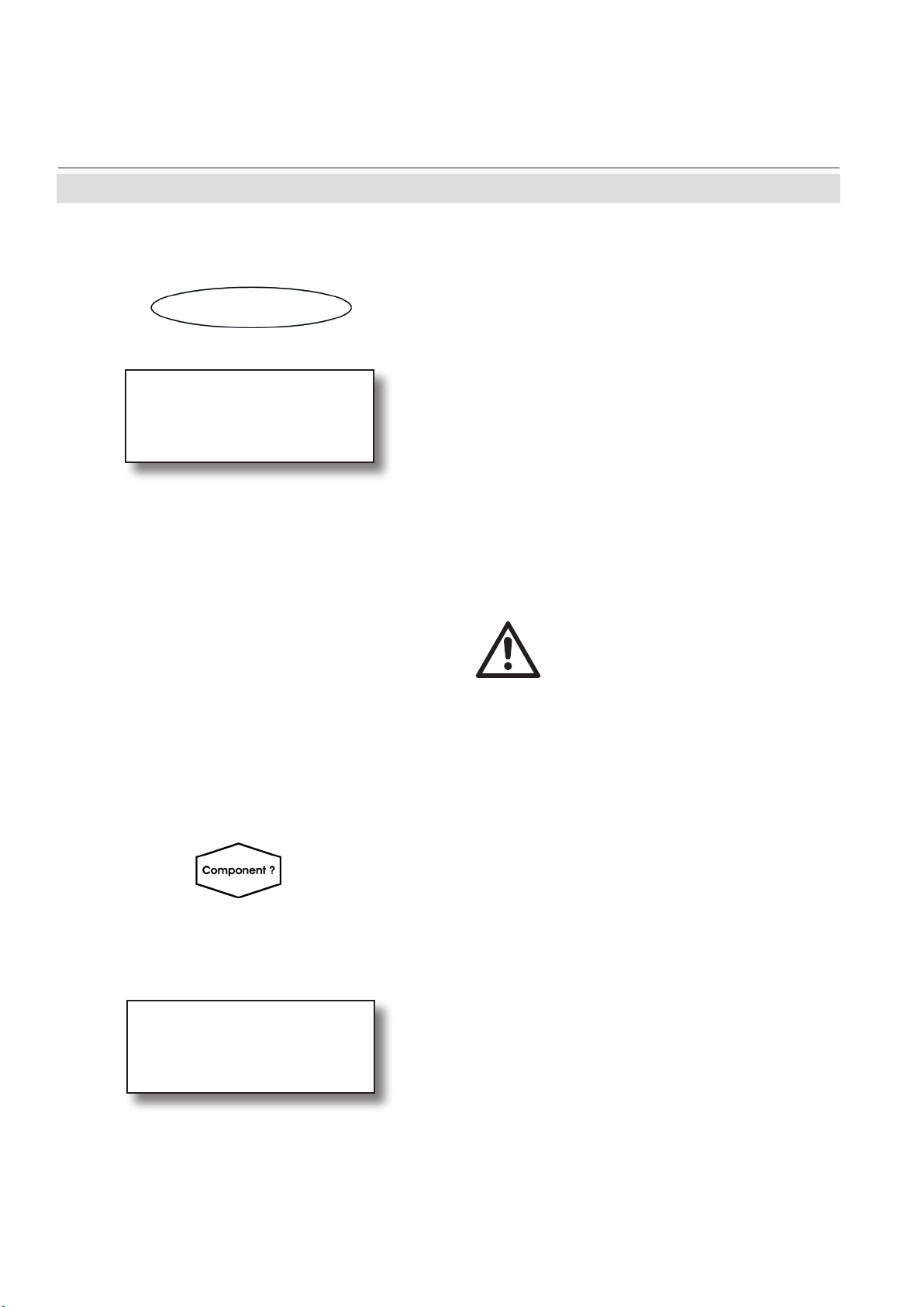
X-STREAM X2FD
4.4.1 Manual Calibration
Control..
Zero calibration..
Span calibration..
Adv.Calibration..
Apply gas..
4.4.1.1 Manual Zero Calibration
Instruction Manual
HASXMDE-IM-EX
03/2012
4.4 Perform a Calibration
Starting from the measurement screen press
the DOWN key to open the MAIN MENU and
enter the CONTROL.. menu.
To start a zero calibration select the rst line:
Before selecting any further line
make sure the required calibra-
tion gas is applied and owing!
CANCEL calibration!
START calibration!
ZeroGas 0.000 ppm
CO2.1 0.200 ppm
Supply all calibration gases with
the same ow as the sample gas
(recommeded approx. 1 l/min),
pressureless and utilizing the
right gas tting.
Ensure the warm-up time after
switching on has elapsed!
Warm-up time is 15 to 50 minutes
depending on installed measu-
ring system and conguration!
Multi-channel unit:
Select the channel to be calibrated in the
SELECT COMPONENT menu.
The rst line gives you the choice to cancel
the procedure now.
Select the second line to start the calibra-
tion.
Line 3 shows the calibration gas setup
(here: required zero gas concentration is
Emerson Process Management GmbH & Co. OHG4-16
Page 95

Instruction Manual
HASXMDE-IM-EX
03/2012
Gasow ZeroGas
CO2.1 0.500 ppm
Procedure Zeroing
Time 10 s
X-STREAM X2FD
4.4 Perform a Calibration
0.000 ppm), while line 4 shows the currently
measured gas concentration.
After having started the calibration, watch the
screen for information about the status:
The rst lines shows the gas (channel) to be
calibrated as well as the currently measured
concentration (after zero calibration this value
should be set to "0").
The line "Procedure" shows what's currently
happening (Zeroing = calibration ongoing;
Purging = waiting for measuring system to
be lled with currently owing gas; None =
calibration nished), while the last line shows
the remaining time till end of calibration
(countdown starting from 40 seconds).
Maintenance
When nished press the LEFT key two times
to return to either
the SELECT COMPONENT menu (multi
channel analyzer only), select another chan-
nel to perform the steps described above to
zero calibrate this channel, too,
or
the CONTROL.. menu, which allows you to
start a span calibration. The procedure and
screens look similiar to those of a zero cali-
bration:
Select SPAN CALIBRATION...
4
Emerson Process Management GmbH & Co. OHG 4-17
Page 96

X-STREAM X2FD
4.4 Perform a Calibration
4.4.1.2 Manual Span Calibration
CANCEL calibration!
START calibration!
SpanGas 20.000 ppm
CO2.1 16.200 ppm
Gasow SpanGas
CO2.1 20.000 ppm
Procedure Spanning
Time 10 s
Instruction Manual
HASXMDE-IM-EX
03/2012
Before selecting any further line
make sure the required calibra-
tion gas is applied and owing!
Multi-channel unit:
Select the channel to be calibrated in the
SELECT COMPONENT menu.
The rst line gives you the choice to immediately cancel the procedure.
Select the second line to start the calibra-
tion.
Line 3 shows the calibration gas setup (here:
required span gas concentration is 20 ppm),
while line 4 shows the currently measured gas
concentration.After having started the calibration watch the screen for status information:
The display shows the currently owing gas,
the gas (channel) to be calibrated as well as
the currently measured concentration (after
span calibration it should be set to the expected value) and a countdown for the current
procedure:
The line "Procedure" shows what's currently
happening (Spanning = calibration ongoing;
Purging = waiting for measuring system to
be lled with currently owing gas; None =
calibration nished), while the last line shows
the remaining time till end of calibration
(countdown starting from 40 seconds).
When nished, either press
the LEFT key two times to return to the
SELECT COMPONENT menu (multi channel
analyzer only), select another channel and
perform the steps described above to zero
calibrate this channel, too,
or
the HOME key to return to the measurement
screen to nish with manual calibration procedures.
Emerson Process Management GmbH & Co. OHG4-18
Page 97

Instruction Manual
HASXMDE-IM-EX
03/2012
Chapter 5
Dismounting and Disposal
5.1 Dismounting and Diposal of the Analyzer
HAZARDS FROM DISMOUNTING
Dismounting instruments installed in hazardous area requires special
instructions to be followed!
Only trained personnel, observing all applicable technical and legal
requirements, and aware of the possible risks is permitted to dismount
these analyzers.
Failure to follow may result in explosion, death or personal injury!
X-STREAM X2FD
EXPLOSION HAZARD WHEN OPEN
Dismounting requires to open the instrument and is permitted only if no
hazardous atmosphere is present and both the instrument and connected
circuitry are de-energized!
Depending on the local regulation this may require a competent hot work
supervisor to issue a hot work permit.
Failure to follow may result in explosion!
HEAVY INSTRUMENT
X-STREAM X2FD analyzers, to which this manual relates, intended
to be wall mounted and/or outdoor installed, weigh up to approx. 63 kg
(139 lbs), depending on included options!
Support the instrument before loosening the xing screws (risk of dropping
instrument).
Two people and/or lifting equipment is required to lift and carry these units.
Dismounting
5
Failure to follow may result in personal injury!
Emerson Process Management GmbH & Co. OHG 5-1
Page 98

X-STREAM X2FD
Follow the safety precautions for all applied gases and gas cylinders.
Before opening the gas lines, they must be purged with air or neutral gas
(N2) to avoid danger from escaping toxic, ammable, explosive or hazardous
gases.
When the instrument has reached the end of its useful life, do not throw it in a
trash can!
This instrument has been made of materials to be recycled by recyclers specialised in this eld. Let the instrument and the packing material duly and environmently friendly be disposed of. Ensure the equipment is free of dangerous
and harmful substances (decontaminated).
Instruction Manual
HASXMDE-IM-EX
03/2012
5.1 Dismounting & Disposal
GASES HAZARDOUS TO HEALTH
Take care of all local regulations for waste treatment.
Consider all instructions regarding dismounting and disposal!
When the instrument has reached the end of its useful life,
• purge all gas lines with inert gas
• ensure all gas lines are pressureless
• disconnect all gas lines
• switch off power and signal lines
• disconnect and remove all electrical connections
• support the instrument before loosening the xing screws (risk of dropping instrument) and
take it off its stand or wall
• ll out the Declaration of Decontamination ( X-STREAM X2 instruction manual) properly
• hand over the dismounted instrument together with the Declaration of Decontamination to
a disposal specialist. The disposal specialist then has to disassemble the instrument, and
recycle and dispose it in compliance with all applicable waste treatment regulations.
Emerson Process Management GmbH & Co. OHG5-2
Page 99

Instruction Manual
HASXMDE-IM-EX
03/2012
X-STREAM X2FD
Appendix
This chapter contains
EC Declaration of Conformity A.1, page A-2
ATEX EC Type Examination Certicate A.2, page A-3
CSA Certicate of Compliance A.3, page A-12
Block diagram A.4, page A-19
Assignment of Terminals and Socket A.5, page A-24
Appendix
Emerson Process Management GmbH & Co. OHG A-1
A
Page 100

X-STREAM X2FD
A.1 EC Declaration of Conformity
A.1 EC Declaration of Conformity
Instruction Manual
HASXMDE-IM-EX
03/2012
Emerson Process Management GmbH & Co. OHGA-2
 Loading...