

Page 1

Instruction Manual
HASAxE-IM-HS
07/2006
Gas Analyzer Series
Instruction Manual
www.EmersonProcess.com
Page 2

ESSENTIAL INSTRUCTIONS
READ THIS PAGE BEFORE PROCEEDING!
Emerson Process Management (Rosemount Analytical) designs, manufactures and tests
its products to meet many national and international standards. Because these
instruments are sophisticated technical products, you MUST properly install, use, and
maintain them to ensure they continue to operate within their normal specifications. The
following instructions MUST be adhered to and integrated into your safety program when
installing, using and maintaining Emerson Process Management (Rosemount Analytical)
products. Failure to follow the proper instructions may cause any one of the following
situations to occur: Loss of life; personal injury; property damage; damage to this
instrument; and warranty invalidation.
• Read all instructions prior to installing, operating, and servicing the product.
• If you do not understand any of the instructions, contact your Emerson Process
Management (Rosemount Analytical) representative for clarification.
• Follow all warnings, cautions, and instructions marked on and supplied with the
product.
• Inform and educate your personnel in the proper installation, operation, and
maintenance of the product.
• Install your equipment as specified in the Installation Instructions of the
appropriate Instruction Manual and per applicable local and national codes.
Connect all products to the proper electrical and pressure sources.
• To ensure proper performance, use qualified personnel to install, operate, update,
program, and maintain the product.
• When replacement parts are required, ensure that qualified people use replacement
parts specified by Emerson Process Management (Rosemount Analytical).
Unauthorized parts and procedures can affect the product’s performance, place the
safe operation of your process at risk, and VOID YOUR WARRANTY. Look-alike
substitutions may result in fire, electrical hazards, or improper operation.
• Ensure that all equipment doors are closed and protective covers are in place,
except when maintenance is being performed by qualified persons, to prevent
electrical shock and personal injury.
The information contained in this document is subject to change without notice.
Edition 2006-07
Emerson Process Management GmbH & Co. OHG
Industriestrasse 1
D-63594 Hasselroth
Germany
T +49 (0) 6055 884-0
F +49 (0) 6055 884-209
Internet: www.EmersonProcess.com
Page 3

Instruction Manual
HASAxE-IM-HS
04/2006
X-STREAM
PREAMBLE
This instruction manual provides information about X-STREAM series gas analyzers
concerning subassemblies, functions, procedures, installation, operation and maintenance.
This instruction manual covers several X-STREAM series analyzer variations and therefore
may describe configurations and/or options not part of your specific analyzer.
Installation and operation of instruments intended to be installed and operated in hazardous
areas is not covered by this instruction manual, but part of the specific instruction manual
shipped together with such analyzers because of the special requirements for working in
hazardous environments!
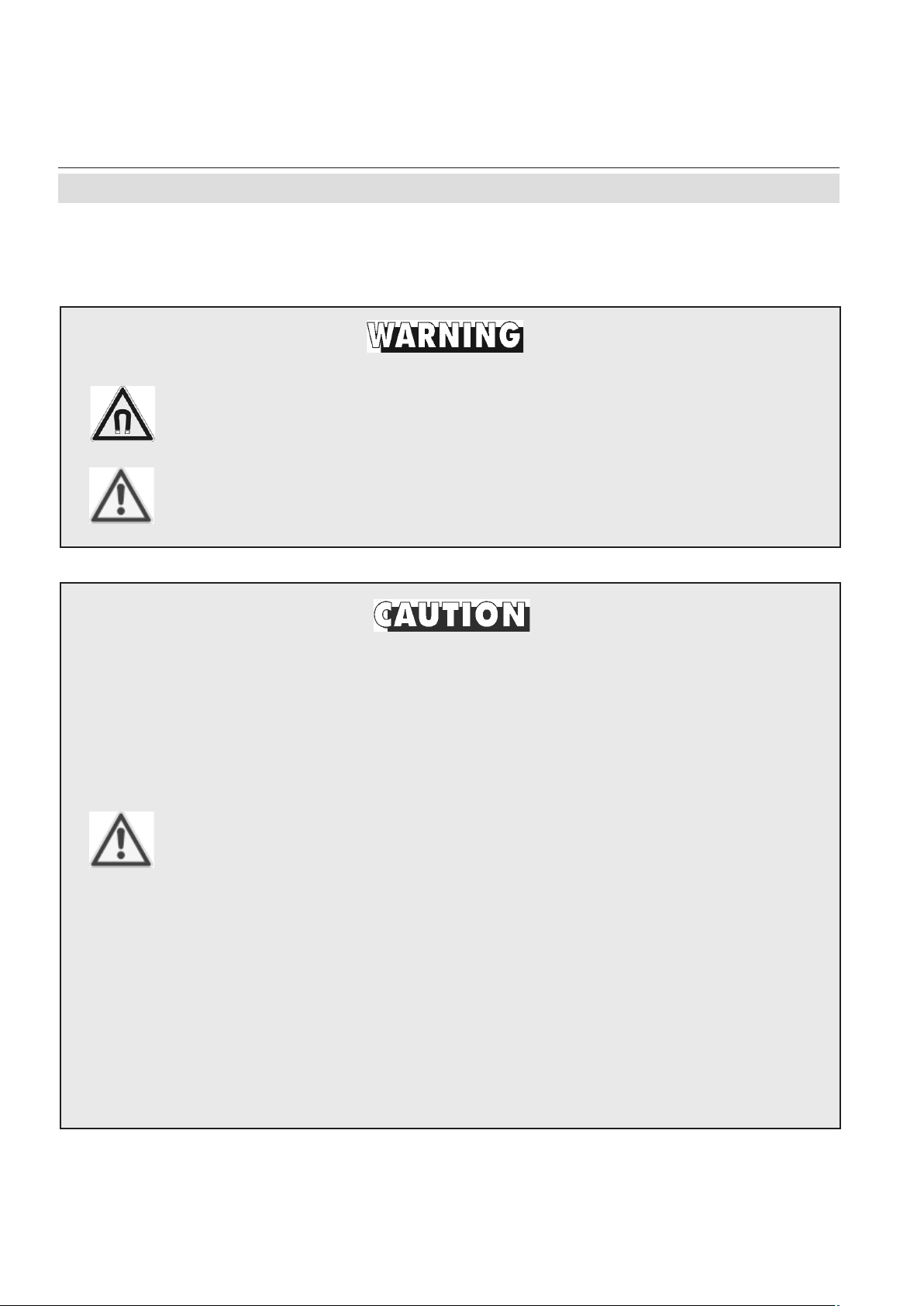
DEFINITIONS
The following definitions apply to WARNINGS, CAUTIONS and NOTES found throughout
this publication.
Highlights an operation or maintenance procedure, practice, condition, statement, etc.
If not strictly observed, could result in injury, death, or long-term health
hazards of personnel.
Safety Instructions
Highlights an operation or maintenance procedure, practice, condition, statement, etc.
If not strictly observed, could result in damage to or destruction of equipment,
or loss of effectiveness.
NOTE
Highlights an essential operating procedure, condition or statement.
Emerson Process Management GmbH & Co. OHG S-1
Page 4

Instruction Manual
X-STREAM
HASAxE-IM-HS
04/2006
IMPORTANT
Safety Instructions
Wiring and Installation of this Apparatus
The following safety instructions apply specifically to all EU member states. They should be strictly
adhered to in order to assure compliance with the Low Voltage Directive. Non-EU st ates should also
comply with the following unless superseded by local or National Standards.
1. Adequate earth connections should be made to all earthing points, internal and external, where
provided.
2. After installation or troubleshooting, all safety covers and safety grounds must be replaced. The
integrity of all earth terminals must be maintained at all times.
3. To ensure safe operation of this equipment, connection to the mains supply should only be
made through a circuit breaker which will disconnect all circuits carrying conductors during a
fault situation. The circuit breaker may also include a mechanically operated isolating switch.
Circuit breakers or switches must comply with a recognized standard such as IEC947. All wiring
must conform with any local standards.
4. Where equipment or covers are marked with the symbol to the right, hazardous
voltages are likely to be present beneath. These covers should only be removed
when power is removed from the equipment — and then by trained service
personnel only .
5. Where equipment or covers are marked with the symbol to the right, there is a
danger from hot surfaces beneath. These covers should only be removed by
trained service personnel when power is removed from the equipment. Certain
surfaces may remain hot to the touch.
6. Where equipment or covers are marked with the symbol to the right, refer to the
Instruction Manual for instructions.
7. Further graphical symbols used in this product:
Electrostatic discharge (ESD)
Harmful (to Health)!
Explosion Hazard!
Toxic!
Heavy Instrument!
Disconnect from Mains!
All graphical symbols used in this product are from one or more of the following standards:
EN61010-1, IEC417, and ISO3864.
Emerson Process Management GmbH & Co. OHGS-2
Page 5

Instruction Manual
HASAxE-IM-HS
04/2006
X-STREAM
Safety Instructions
Operating and Maintaining this Apparatus
This instrument has left the factory in compliance with all applicable safety regulations.
To maintain this operating condition, the user
must strictly follow the instructions and consider
the warnings in this manual or provided on the
instrument.
Before switching on the instrument, verify that
the electrical supply voltage matches the
instrument´s operating voltage as set in the
factory .
Any interruption in the instrument´s ground line,
whether inside or outside the instrument, or
removal or interruption of its ground line
connection, could result in hazardous operating
conditions. Intentionally interrupting the
instrument´s protective ground is strictly prohibited.
Opening cover panels could expose voltagecarrying components. Connectors may also be
under voltage. The instrument must be
disconnected from all electrical supplies before
attempting any calibrations, maintenance
operations, repairs or component
replacements requiring opening of the
instrument. Any calibrations, maintenance
operations, or repairs that need the instrument
to be opened while connected to electrical
supplies should be subject to qualified
technicians familiar with the hazards involved
only!
Observe all applicable regulations when
operating the instrument from an autotransformer or variac.
Substances hazardous to health may emerge
from the instrument‘s exhaust.
Please pay attention to the safety of your
operation personnel. Protective measures
must be taken, if required.
Safety Instructions
Use only fuses of the correct type and current
ratings as replacements. Using repaired fuses
and short circuiting of fuse holders is prohibited.
Emerson Process Management GmbH & Co. OHG S-3
Page 6
Instruction Manual
X-STREAM
Safety Instructions
HASAxE-IM-HS
04/2006
INTENDED USE STATEMENT
X-Stream series gas analyzers are intended to be used as analyzers for industrial purposes.
They must not be used in medical, diagnostic or life support applications nor as safety
devices, and no independent agency certifications or approvals are to be implied as
covering such applications!
AUTHORIZED PERSONNEL
If this equipment is used in a manner not specified in these instructions, protective systems
may be impaired.
SAFETY SUMMARY
T o avoid loss of life, personal injury and damage to this equipment and on-site property , do
not operate or service this instrument before reading and understanding this instruction
manual and receiving appropriate training. Save these instructions.
ELECTRICAL SHOCK HAZARD !
Do not operate without covers secure. Do not open while energized.
Installation requires access to live parts which can cause death or serious
injury .
For safety and proper performace this instrument must be connected to a
properly grounded three-wire source of power.
TOXIC GASES !
This unit’s exhaust may contain toxic gases such as sulfur dioxide.
These gases can cause serious injuries.
Aviod inhalation of the exhaust gases at the exhaust fitting.
Connect exhaust outlet to a safe vent. Check vent line and connections for
leakage.
Keep all fittings tight to avoid leaks. See section 7-2, page 7-2 for leak test
instructions.
Emerson Process Management GmbH & Co. OHGS-4
Page 7
Instruction Manual
HASAxE-IM-HS
04/2006
X-STREAM
Safety Instructions
EXPLOSION HAZARD !
Do not operate nor install these instruments in hazardous areas without additional measures!
HEAVY INSTRUMENTS !
The analyzer variation X-STREAM F, intended to be wall mounted and/or
outdoor installed, weighs up to approx. 26 kg (57 lbs), depending on
included options!
Use two people and/or suitable tools for transportation and lifting these
instruments!
Take care to use anchors and bolts specified to be used for the weight of
the units!
T ake care the wall or stand the unit is intended to be inst alled at is solid and
stable to hold the units!
Safety Instructions
HIGH TEMPERATURES !
While working with photometers and/or thermostated components inside
the analyzers hot components may be accessible!
Emerson Process Management GmbH & Co. OHG S-5
Page 8

X-STREAM
GASES AND GAS CONDITIONING
Take care of the safety instructions applicable for the gases (sample
gases and test gases) and for the gas bottles containing these gases!
Instruction Manual
HASAxE-IM-HS
04/2006
Safety Instructions
INJURY HAZARD !
EXPLOSION HAZARD !
Supplying flammable gases of concentrations above the lower explosion
limit (LEL) we recommend to utilize one or more of the following measures:
• Purging the housing with inert gas
• Internal tubing with stainless steel
• Flame arrestors at gas input and output fittings
• Intrinsically safe paramagnetical or thermal conductivity sensors
Supplying explosive gases is not permitted ! (Explosive gases are mixtures
of flammable gases of concentrations between the explosion limits with air
or oxygen).
Before opening gas paths they must be purged with ambient air or
neutral gas (N2) to avoid hazards caused by toxic, flammable,
explosive or harmful to health sample gas components!
Emerson Process Management GmbH & Co. OHGS-6
Page 9

Instruction Manual
HASAxE-IM-HS
04/2006
POWER SUPPLY
V erify the mains voltage at site of inst allation corresponds to the analyzer´s
rated voltage as given on the nameplate label!
V erify the safety instruction given by power supply unit manufacturer !
CONNECTING INSTRUMENTS FOR FIXED INSTALLATION
X-STREAM
Safety Instructions
Safety Instructions
Installation and connecting mains and signal cables are subject to qualified
personnel only taking into account all applicable standards and legislative
requirements!
Failure to follow may cause warranty invalidation, property damage and/or
personal injury or death! Connecting mains and signal cables to internal
srew terminals requires working at open housing near life parts!
Installation of this instrument is subject to qualified personnel only , familiar
with the resulting potential risks!
The gas analyzers do not provide a mains power switch and are operable
when connected to power.
The gas analyzers do not provide a mains switch! A mains switch or circuit
breaker (to comply with IEC 60947-1 /-3) has to be provided in the building
installation. This switch has to be installed near by analyzer, must be easily
operator accessible and has to be assigned as disconnector for the analyzer.
Cables for external data processing must be double insulated for mains
voltage when used inside the instrument!
If double insulation is not available signal cables inside the analyzer must
be installed in a way that a distance of at least 5 mm is ensured permanently
(e.g. by utilizing cable ties).
Emerson Process Management GmbH & Co. OHG S-7
Page 10
X-STREAM
These instruments provide a protective earth terminal. To prevent electrical
shock hazards the instrument must be connected to a protective earth.
Therefore the instrument has to be connected to mains by using a three
wire mains cable with earth conductor!
Any interruption of the earth connector inside or outside the instrument or
disconnecting the earth terminal may cause potential electrical shock
hazzard! Intended interruption of protective earth connections is not
permitted!
Instruction Manual
HASAxE-IM-HS
04/2006
Safety Instructions
ELECTRICAL SHOCK HAZARD !
Emerson Process Management GmbH & Co. OHGS-8
Page 11
Instruction Manual
HASAxE-IM-HS
04/2006
General Operating Instructions
General Operating Instructions
X-STREAM
DANGER TO LIFE ! EXPLOSION HAZARD !
V erify all gas lines are connected as described within this manual and tight!
Improper gas connections may cause explosion, serious injury or death!
Exhaust may contain hydrocarbons and other toxic gases, e.g. carbon
monoxide. Carbon monoxide is toxic!
• Indoor installation area has to be clean, free from moisture, excessive vibration and frostprotected.
• T ake care to meet the permissible ambient temperatures as given in the technical data section!
Instruments must not be exposed to direct sunlight nor sources of heat. Do not cover venting
openings and take care to mount the instrument in a distance to walls not affecting venting.
• Do not interchange gas inlet and outlet! All gases must be conditioned before supplying! When
supplying corrosive gases ensure that gas path components are not affected!
• Max. permissible gas pressure: 1,500 hPa (7.5 psig), except with paramagnetic Oxygen sensor
(atmospheric pressure;
page 3-17)!
Safety Instructions
• Exhaust lines must be installed in a descending way , need to be pressureless, frost-protected
and in compliance with applicable legislative requirements!
• When it is necessary to open gas paths seal the analyzer‘s gas fittings by using PVC caps to
avoid pollution of the internal gas path by moisture, dust, etc.
• T o stay in compliance with regulations regarding electromagnetic compatibility it is recommended
to use only shielded cables, as optionally available from Emerson Process Management or
equivalent. Customer has to take care that the shield is connected in proper way ( section
4-5, page 4-29). Shield and signal connector enclosure need to be conductively connected,
submin-d plugs and sockets must be screwed to the analyzer .
• Using external submin-d-to-terminal adaptor elements (option) affects electromagnetic
compatibility . In this case the customer has to take measures to stay in compliance and has to
declare conformity , when required by legislation (e.g. European EMC Directive).
Emerson Process Management GmbH & Co. OHG S-9
Page 12
X-STREAM
Magnetically Operated Front Panel
Magnetically Operated Front Panel
Persons with cardiac pacemakers should absolutely avoid magnetic
fields !
Negative effects on persons beyond those described above caused by
magnetic fields are not known. It is presumed that persons showing allergic
reaction on contact with ceramic or metallic material show the same
behavior on contact with magnetic material.
Instruction Manual
HASAxE-IM-HS
04/2006
DANGER TO LIFE !
Permanent magnets are surrounded by magnetic fields. These magnetic
fields can disturb and even destroy sensitive electronic measuring devices,
but also mechanical watches, credit cards, etc.
Usually a distance of 20 inch (0.5 m) is enough to avoid damages. All sintered
permanent magnets are hard and brittle. Hitting of sintered permanent
magnets by the magnetic attraction causes splitting into fragments with many
sharp edges. This especially occurs with high energy magnets, and can
also cause skin bruises by high attraction.
High energy magnets made of rare-earth materials have to be stored dry,
otherwise the surfaces would oxidise. Unprotected operation in a humid
environment may cause corrosion. Avoid damaging the protective galvanic
coating.
A storage in a hydrogen atmosphere destroys these magnets. A
demagnetisation is caused when permanent magnet materials have been
exposed in a radioactive radiation for a long time.
For air transportation of magnetic material the IATA instructions have to be
observed:
Magnetic fields are not allowed to penetrate the package, if necessary the
magnets have to be shorted using a metal plate.
Emerson Process Management GmbH & Co. OHGS-10
Page 13

Instruction Manual
HASAxE-IM-HS
05/2006
To find information about see chapter
Safety measures ................................................ S
The different instruments designs .................. 1
The instruments technical data ....................... 2
Measuring principles characteristics ............. 3
How to install the instruments.......................... 4
X-STREAM
SHORT FORM GUIDE FOR THIS MANUAL
Software menu structure, how to navigate
and menu entries descriptions ........................ 5
st
1
startup procedures,
checking the instrument‘s setup..................... 6
Basic procedures .............................................. 7
Maintenance procedures ................................. 7
Status messages and troubleshooting .......... 8
Modbus Parameters .......................................... 9
Table of Contents
Emerson Process ManagementGmbH & Co. OHG
T-1
Page 14

Instruction Manual
X-STREAM
HASAxE-IM-HS
05/2006
TABLE OF CONTENTS
Preamble S-1
Definitions S-1
Safety Instructions S-2
General Operating Instructions ............................................................................................ S-9
Magnetically Operated Front Panel.................................................................................... S-10
Chapter 1 Technical Description 1-1
1-1 Overview .....................................................................................................................1-1
1-2 X-STREAM General Purpose Tabletop or Rack Mount Version ............................ 1-4
1-3 X-STREAM F (Field Housing).................................................................................... 1-6
1-4 Reserved For Future Use ........................................................................................ 1-11
1-5 Gaspath Design ........................................................................................................1-12
1-5-1 Gas Paths Materials .............................................................................................1-12
1-5-2 Safety Filter........................................................................................................... 1-12
1-5-3 Fittings .................................................................................................................. 1-12
1-5-4 Piping.................................................................................................................... 1-12
1-5-5 Gas Path Variations ............................................................................................. 1-13
1-6 Optional Gas Path Components............................................................................. 1-15
1-6-1 Internal Sample Gas Pump ................................................................................. 1-15
1-6-2 Internal Valve Block.............................................................................................1-15
1-6-3 Internal Flow Monitor...........................................................................................1-15
1-6-4 Internal Barometric Pressure Sensor ................................................................ 1-15
1-6-5 Optional Heated Compartment...........................................................................1-16
1-7 Interfaces ..................................................................................................................1-17
1-7-1 Analog Outputs .................................................................................................... 1-17
1-7-2 Modbus Interface ................................................................................................. 1-17
1-7-3 Status Signals (NAMUR) .....................................................................................1-17
1-8 Optional Interfaces................................................................................................... 1-18
1-8-1 Digital Outputs ..................................................................................................... 1-18
1-8-2 Digital Inputs ........................................................................................................ 1-18
1-8-2-1 Remotely Activating a Calibration Procedure using IN 1 to IN 3................. 1-19
1-8-2-2 V alve Control.................................................................................................... 1-20
1-8-2-3 Remote Pump Control .................................................................................... 1-20
T-2
Emerson Process Management GmbH & Co. OHG
Page 15

Instruction Manual
HASAxE-IM-HS
05/2006
X-STREAM
Table of Contents
Chapter 2 Technical Data 2-1
2-1 Common Technical Data ........................................................................................... 2-2
2-2 Model Specific Technical Data.................................................................................. 2-5
2-2-1 X-STREAM GP, GPS Tabletop or Rack Mount Version....................................... 2-5
2-2-1-1 Terminals Version.............................................................................................. 2-6
2-2-1-2 Sockets Version .................................................................................................2-8
2-2-2 X-STREAM F Field Housing................................................................................2-10
2-3 Information on the Nameplate Label ......................................................................2-13
Chapter 3 Measuring Principles 3-1
3-1 Infrared Measurement (IR), Ultraviolet Measurement (UV).....................................3-1
3-1-1 Interference Filter Correlation (IFC) .....................................................................3-1
3-1-2 Opto Pneumatic Measuring Principle .................................................................. 3-3
3-1-3 Technical Implementation..................................................................................... 3-4
3-2 Oxygen Measurement ................................................................................................3-9
3-2-1 Paramagnetic Measurement................................................................................. 3-9
3-2-2 Electrochemical Measurement ........................................................................... 3-11
3-2-3 Special Hints on Oxygen Sensors ..................................................................... 3-13
3-3 Thermal Conductivity Measurement ......................................................................3-14
3-3-1 Principle of Operation.......................................................................................... 3-14
3-3-2 Technical Implementation................................................................................... 3-15
3-4 Measurement Specification ....................................................................................3-16
Table of Contents
Chapter 4 Installation 4-1
4-1 Abstract....................................................................................................................... 4-1
4-2 Gas Conditioning .......................................................................................................4-2
4-3 Electrical Connections ..............................................................................................4-5
4-4 Detailled Installation Instructions ............................................................................. 4-6
4-4-1 X-STREAM GP, X-STREAM GPS...........................................................................4-6
4-4-1-1 Plugs & Sockets Version .................................................................................. 4-7
4-4-1-2 Terminals Version............................................................................................ 4-13
4-4-2 X-STREAM F......................................................................................................... 4-20
4-5 Hints on Wiring Signal Inputs and Outputs........................................................... 4-29
4-5-1 Electrical Connections in General...................................................................... 4-29
4-5-2 Wiring Inductive Loads .......................................................................................4-31
4-5-3 Driving Multiple Loads ........................................................................................ 4-31
4-5-4 Driving High Current Loads................................................................................ 4-32
Emerson Process Management GmbH & Co. OHG
T-3
Page 16

Instruction Manual
X-STREAM
HASAxE-IM-HS
05/2006
Table of Contents
Chapter 5 User Interface and Software Menus 5-1
5-1 Abstract....................................................................................................................... 5-1
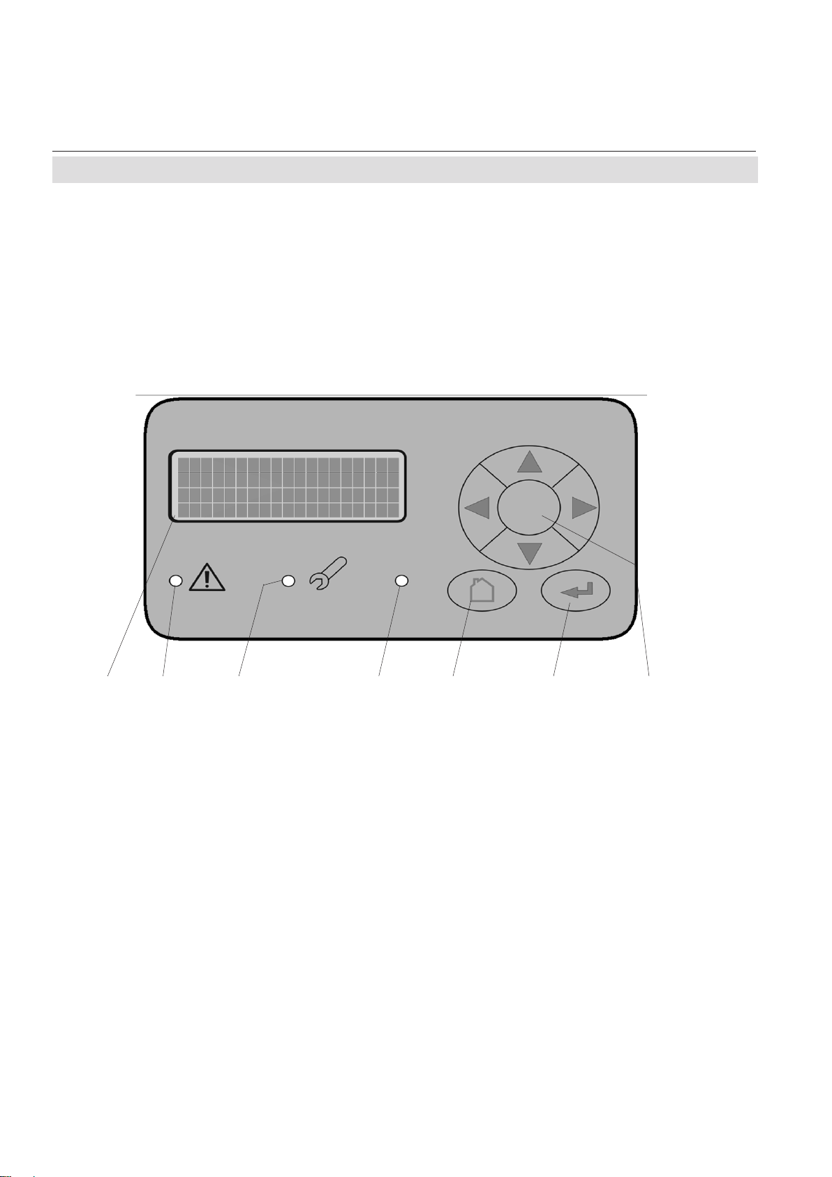
5-2 The User Interface...................................................................................................... 5-1
5-2-2 The Status LEDs .................................................................................................... 5-2
5-2-1 The Display............................................................................................................. 5-2
5-2-3 The Keys ................................................................................................................. 5-3
5-2-3-1 Magnetically Operated Front Panel ................................................................. 5-4
5-3 Software...................................................................................................................... 5-5
5-3-1 Power-On Sequence ............................................................................................. 5-5
5-3-2 Measuring Screen .................................................................................................. 5-5
5-3-3 Menu Structure ......................................................................................................5-6
5-3-4 Navigating and Editing..........................................................................................5-6
5-3-5 Access Levels ........................................................................................................ 5-8
5-3-6 Special Screens ..................................................................................................... 5-9
5-4 Menu System ............................................................................................................5-10
5-4-1 Power-On and Measuring Screen ...................................................................... 5-11
5-4-2 Control Menu ........................................................................................................ 5-13
5-4-2-1 Zero Calibration Menu.....................................................................................5-14
5-4-2-2 Span Calibration Menu ................................................................................... 5-15
5-4-2-3 Advanced Calibration Menu ........................................................................... 5-16
5-4-2-4 Calibration Status Screen...............................................................................5-17
5-4-2-5 Apply Gas Menu............................................................................................... 5-18
5-4-2-6 Acknowledgements Menu .............................................................................. 5-19
5-4-3 Setup Menu .......................................................................................................... 5-20
5-4-3-1 Display Setup Menu ........................................................................................5-21
5-4-3-1-1 Display Language Setup Menu .................................................................5-23
5-4-3-1-2 Menu Access Setup Menu..........................................................................5-24
5-4-3-1-3 Component Setup Menu ............................................................................5-25
5-4-3-2 Calibration Setup Menu ..................................................................................5-26
5-4-3-2-1 Calibration Gases Setup Menu ..................................................................5-27
5-4-3-2-2 Interval Time Setup Menu...........................................................................5-28
5-4-3-3 Measurement Setup Menu..............................................................................5-29
5-4-3-3-1 Signal Damping Setup Menu .....................................................................5-30
5-4-3-3-2 Cross Interference Setup Menu.................................................................5-31
5-4-3-3-3 AD Conversion Setup Menu ......................................................................5-32
5-4-3-4 In/Outputs Setup Menu ...................................................................................5-33
5-4-3-4-1 Analog Output Setup Menu........................................................................5-34
T-4
Emerson Process Management GmbH & Co. OHG
Page 17

Instruction Manual
HASAxE-IM-HS
05/2006
X-STREAM
Table of Contents
5-4-3-4-1-1 Analog Output Signal Setup ..................................................................5-35
5-4-3-4-1-2 Analog Output Range Setup..................................................................5-36
5-4-3-4-1-3 Analog Output Signal Scaling Setup ....................................................5-38
5-4-3-4-1-4 Analog Output Signal Trimming ............................................................5-39
5-4-3-4-2 V alve Assignment........................................................................................5-40
5-4-3-5 Installed Options Setup Menu ........................................................................ 5-41
5-4-3-6 Communication Setup Menu..........................................................................5-42
5-4-3-7 Alarms Setup Menu ......................................................................................... 5-43
5-4-3-8 Save-Load Menu ..............................................................................................5-44
5-4-3-9 Miscellaneous Screen.....................................................................................5-46
5-4-4 Status Menu .........................................................................................................5-47
5-4-4-1 Failure Status Screen......................................................................................5-48
5-4-4-2 Check Requests Status Screen..................................................................... 5-49
5-4-4-3 Function Check Status Screen ...................................................................... 5-50
5-4-4-4 Off Spec Status Screen...................................................................................5-51
5-4-4-5 Calibration Status Screen...............................................................................5-52
5-4-4-6 Measurement Status Screen .......................................................................... 5-53
5-4-4-7 Alarms Status Screen .....................................................................................5-54
5-4-5 Info Menu ..............................................................................................................5-55
5-4-5-1 Measuring Range Info Screen........................................................................ 5-56
5-4-5-2 Factory Settings Screen .................................................................................5-57
5-4-5-3 Installed Options Info Screen .........................................................................5-58
Table of Contents
Chapter 6 Initial Startup 6- 1
6-1 Abstract....................................................................................................................... 6-1
6-2 Checking the Instrument's Setup.............................................................................6-2
6-2-1 Instrument's Language Setup.............................................................................. 6-3
6-2-2 Display Information Setup ....................................................................................6-4
6-2-3 Calibration Data Setup ..........................................................................................6-4
6-2-4 Analog Output Setup............................................................................................. 6-7
6-2-5 Concentration Alarms Setup ..............................................................................6-12
Chapter 7 Maintenance 7-1
7-1 Abstract....................................................................................................................... 7-1
7-2 Performing a Leak Test.............................................................................................. 7-2
Emerson Process Management GmbH & Co. OHG
T-5
Page 18

Instruction Manual
X-STREAM
HASAxE-IM-HS
05/2006
Table of Contents
7-3 Calibration Procedures ............................................................................................7-3
7-3-1 Preparing a Calibration .........................................................................................7-4
7-3-2 Manual Calibration................................................................................................. 7-7
7-3-2-1 Manual Zero Calibration.................................................................................... 7-7
7-3-2-2 Manual Span Calibration ..................................................................................7-8
7-3-3 Advanced Calibration..........................................................................................7-10
7-3-3-1 Additional Preparations for Advanced Calibration ...................................... 7-11
7-3-3-2 Zero All Calibration .......................................................................................... 7-14
7-3-3-3 Span All Calibration .........................................................................................7-16
7-3-3-4 Zero & Span All Calibration............................................................................. 7-18
7-3-4 Auto Calibration ................................................................................................... 7-21
7-3-4-1 Additional Preparations for Auto Calibration................................................ 7-21
7-3-4-2 Zero Auto Calibration ......................................................................................7-24
7-3-4-3 Span Auto Calibration .....................................................................................7-26
7-3-4-4 Unattended Auto Calibration.......................................................................... 7-28
7-3-5 Resetting a Calibration........................................................................................7-30
7-3-6 Verifying a Calibration .........................................................................................7-30
7-3-7 Cancelling an Ongoing Calibration....................................................................7-31
7-3-8 Cross Interference Compensation ..................................................................... 7-33
7-4 Replacing the ElectrochemicalSensor .................................................................7-35
7-4-1 Precautions for Sensor Handling ......................................................................7-37
7-4-2 Opening the Analyzer.......................................................................................... 7-38
7-4-2-1 Opening X-STREAM GP / GPS ....................................................................... 7-39
7-4-2-2 Opening X-STREAM F.....................................................................................7-39
7-4-3 Locating the Sensor ...........................................................................................7-40
7-4-4 Sensor Unit Disassembly ................................................................................... 7-41
7-4-5 Sensor Amplifier Adjustment ..............................................................................7-42
7-4-6 Finalizing the Sensor Replacement................................................................... 7-43
7-5 Cleaning the Instrument's Outside.........................................................................7-44
7-6 Save / Restore Configuration Data Sets ................................................................ 7-45
7-6-1 Save CfgData to UserData .................................................................................. 7-46
7-6-2 Restore UserData to CfgData ............................................................................. 7-47
7-6-3 Restore FactData to CfgData..............................................................................7-48
7-6-4 Save / Restore to an External Device................................................................. 7-49
7-6-4-1 Save CfgData to COMPort ..............................................................................7-50
7-6-4-2 Restore COMPort to CfgData .........................................................................7-52
T-6
Emerson Process Management GmbH & Co. OHG
Page 19

Instruction Manual
HASAxE-IM-HS
05/2006
Table of Contents
X-STREAM
Chapter 8 Troubleshooting 8-1
8-1 Abstract....................................................................................................................... 8-1
8-2 Solving Problems Indicated by Status Messages ..................................................8-2
8-3 Solving Problems Not Indicated by Status Messages ...........................................8-8
8-4 Troubleshooting on Components..........................................................................8-12
8-4-1 Opening X-STREAM GP / GPS............................................................................8-12
8-4-2 Opening X-STREAM F ......................................................................................... 8-12
8-4-3 Measuring Points................................................................................................. 8-13
8-4-3-1 Measuring Points at BKS Board ....................................................................8-13
8-4-3-1-1 Supply voltage +6 V ....................................................................................8-13
8-4-3-1-2 Positive reference voltage..........................................................................8-13
8-4-3-1-3 Negative reference voltage............................................................................. 8-15
8-4-3-1-4 Temperature sensor....................................................................................8-15
8-4-3-1-5 Light barrier signal ......................................................................................8-15
8-4-3-1-6 Analog Preamplifier.....................................................................................8-16
8-4-3-2 Measuring Points at OXS Board (Electrochemical Oxygen Measurement)8-17
8-4-3-2-1 Sensor Signal ..............................................................................................8-17
8-4-4 BKS 20 Board Jumper Configuration................................................................8-18
8-4-5 Fuse on BKS 20 Board .......................................................................................8-19
Table of Contents
Chapter 9 Modbus Functions 9-1
9-1 Abstract....................................................................................................................... 9-1
9-2 Supported Functions ................................................................................................ 9-2
9-3 List of Parameters and Registers ............................................................................. 9-2
9-4 Comparison of Registers and Parameters ............................................................9-17
Chapter 10 Service Information 10-1
10-1 Return of Material..................................................................................................... 10-1
10-2 Customer Service .................................................................................................... 10-2
10-3 T raining ..................................................................................................................... 10-2
Appendix A-1
A-1 Modbus Implementation........................................................................................... A-2
A-2 EC Declaration of Conformity................................................................................ A-12
A-3 Block Diagrams ....................................................................................................... A-13
Emerson Process Management GmbH & Co. OHG
T-7
Page 20

Instruction Manual
X-STREAM
HASAxE-IM-HS
05/2006
Index of Figures
Index of Figures
Fig. 1-1: X-STREAM GP, GPS, front side view......................................................................................................1-4
Fig. 1-2: X-STREAM GP, terminals version, rear side view .................................................................................1-5
Fig. 1-3: X-STREAM GPS, plugs and sockets version, rear side view................................................................1-5
Fig. 1-4: X-STREAM F, front side view & rear side view at carrying handle ......................................................1-7
Fig. 1-5: X-STREAM F, front panel........................................................................................................................1-8
Fig. 1-6: X-STREAM F, bottom view .....................................................................................................................1-9
Fig. 1-7: X-STREAM F, mains and signal terminals (front door removed).......................................................1-10
Fig. 1-8: Single channel or serial tubing ............................................................................................................1-13
Fig. 1-9: Dual channel parallel tubing.................................................................................................................1-12
Fig. 1-10: Single channel or serial tubing, with options ...................................................................................1-14
Fig. 1-1 1: Dual channel parallel tubing, with options ........................................................................................1-15
Fig. 1-12: Optional Heated Compartment ...........................................................................................................1-16
Fig. 1-13: Digital Outputs - Schematic ................................................................................................................1-18
Fig. 1-14: Digital Inputs - Priorities ......................................................................................................................1-19
Fig. 2-1: X-STREAM GP, GPS - dimensions [approx. mm (inch)] .......................................................................2-5
Fig. 2-2: X-STREAM GP , (terminals version) - terminals and fuse holders........................................................2-7
Fig. 2-3: X-STREAM GPS, (sockets version) - power and signals connectors ..................................................2-8
Fig. 2-4: X-STREAM F - dimensions (approx. mm [inch]) .................................................................................2-10
Fig. 2-5: X-STREAM F - mains terminals / fuse holders ....................................................................................2-11
Fig. 2-6: X-STREAM F - signals terminals ..........................................................................................................2-12
Fig. 2-7: Analyzer Nameplate Label (example)...................................................................................................2-13
Fig. 3-1: Absorption Bands of Measured Gases and Transmission of Interference Filters ................................3-2
Fig. 3-2: Gas Detector Design Principle ................................................................................................................3-3
Fig. 3-3: IR Photometer Assembly Principle .........................................................................................................3-5
Fig. 3-4: Photometer Assembly with Pyroelectrical Detector ..............................................................................3-7
Fig. 3-5: IR & UV Photometer Assemblies with Gas Detectors.............................................................................3-8
Fig. 3-6: Paramagnetic Oxygen Detector, Assembly Principle .......................................................................... 3-10
Fig. 3-7: Electrochemical Sensor - Assembly Principle..................................................................................... 3-11
Fig. 3-8: Electrochemical reaction of Oxygen Sensor .......................................................................................3-12
Fig. 3-9: Wheatstone Bridge ................................................................................................................................3-15
Fig. 3-10a: TC cell, exterior view .........................................................................................................................3-15
Fig. 3-10b: TC cell - sectional view......................................................................................................................3-15
Fig. 4-0: Example of gas fittings label...................................................................................................................4-3
Fig. 4-1: Bypass Mode Installation.........................................................................................................................4- 5
Fig. 4-2:Frontal view...............................................................................................................................................4-6
Fig. 4-3: Rear panel - plugs & sockets version .....................................................................................................4-7
Fig. 4-4: Socket X1 - pin assignment ....................................................................................................................4-8
Fig. 4-5: Socket X2 - pin assignment ....................................................................................................................4-9
Fig. 4-7: Plug X3 - pin assignment ......................................................................................................................4-10
Fig. 4-6: Relay status signals, block diagram .....................................................................................................4-10
Fig. 4-8: Socket X4 - pin assignment ..................................................................................................................4-11
T-8
Emerson Process Management GmbH & Co. OHG
Page 21

Instruction Manual
HASAxE-IM-HS
05/2006
X-STREAM
Index of Figures
Fig. 4-9: IEC mains input plug .............................................................................................................................4-12
Fig. 4-10: Rear panel - terminals version ............................................................................................................4-13
Fig. 4-1 1: Analog Signal Output Terminals ........................................................................................................4-14
Fig. 4-12: Modbus Interface Terminals ................................................................................................................4-15
Fig. 4-14: Relay Status Terminals ........................................................................................................................4-16
Fig. 4-13: Relay status signals, block diagram ...................................................................................................4-16
Fig. 4-15: Digital Input & Output Terminals ........................................................................................................4-17
Fig. 4-16: Mains terminals....................................................................................................................................4-18
Fig. 4-17: X-STREAM F ........................................................................................................................................4-20
Fig. 4-18: X-STREAM F -Allocation of terminals and gas fittings.....................................................................4-21
Fig. 4-19: X-STREAM F - Analog output terminals ............................................................................................4-23
Fig. 4-20: X-STREAM F - Modbus interface terminals .......................................................................................4-24
Fig. 4-22: X-STREAM F - Relay Status Terminals ..............................................................................................4-25
Fig. 4-21: Relay status signals, block diagram ...................................................................................................4-25
Fig. 4-23: Digital Input & Output Terminals ........................................................................................................4-26
Fig. 4-24: Power terminals ...................................................................................................................................4-27
Fig. 4-25: Shielded Signal Cable, shield connected at both ends ....................................................................4-28
Fig. 4-26: Shielded Signal Cable, shield connected at one end .......................................................................4-30
Fig. 4-27: Double-shielded Signal Cable, shields connected at both sides......................................................4-30
Fig. 4-28: Suppressor Diode for Inductive Loads ...............................................................................................4-31
Fig. 4-29: ”Serial” Wiring ....................................................................................................................................4-31
Fig. 4-30: Running Supply Lines "parallel”........................................................................................................4-32
Fig. 4-31: Driving High Current Loads ................................................................................................................4-32
Table of Contents
Fig. 5-1: X-STREAM user interface........................................................................................................................5-1
Fig. 5-2: X-STREAM magnetic tool .......................................................................................................................5-4
Fig. 5-3: X-STREAM Software menu structure ...................................................................................................5-12
Fig. 6-1: Thresholds defining a window..............................................................................................................6-15
Fig. 6-2: HIGH and HIGH-HIGH alarm mode ........................................................................................................6-16
Fig. 6-3: LOW and LOW-LOW alarm mode ........................................................................................................6-17
Fig. 7-1: Leak Testing with U-turn manometer .....................................................................................................7-2
Fig. 7-2: Calibration improvement by variable valve assignments ................................................................... 7-11
Fig. 7-3: Calibration improvement by variable valve assignments ................................................................... 7-21
Fig. 7-3: Graphical Explanation of Interval Time Settings.................................................................................7-28
Fig. 7-4: X-STREAM interior views......................................................................................................................7-38
Fig. 7-5: X-STREAM GP Interior View .................................................................................................................7-40
Fig. 7-6: Cardcage Detail ......................................................................................................................................7-41
Fig. 7-7: Allocation of eO2 Sensor Unit ..............................................................................................................7-40
Fig. 7-8: Purged Box Detail ..................................................................................................................................7-40
Fig. 7-9: Sensor Unit Assembly ...........................................................................................................................7-40
Fig. 7-10: Sensor Block Assembly ......................................................................................................................7-41
Fig. 7-1 1: OXS Board, top view............................................................................................................................7-43
Emerson Process Management GmbH & Co. OHG
T-9
Page 22

Instruction Manual
X-STREAM
HASAxE-IM-HS
05/2006
Index of Tables
Fig. 8-0: X-STREAM F interior view with flapped front panel.............................................................................8-8
Fig. 8-1: X-STREAM interior views......................................................................................................................8-12
Fig. 8-2: BKS Board (section), measuring points ...............................................................................................8-13
Fig. 8-3:Light barrier signal .................................................................................................................................8-15
Fig. 8-4: OXS board, assembled, top view..........................................................................................................8-17
Fig. 8-5: BKS board (section) ...............................................................................................................................8-18
Fig. 8-6: Allocation of fuse on BKS board ..........................................................................................................8-19
Index of Tables
Table 1-1: Digital Inputs IN4-IN7, array ................................................................................................................1-20
Table 3-1: Solvent Resistant Sensor: Approved Solvents....................................................................................3-9
Table 3-2: Medium affected Materials within Paramagnetic Oxygen Sensor ...................................................3-10
Table 3-3: Paramagnetic Oxygen Measurement, cross interference by accompanying gases........................3-13
Table 3-4: Electrochemical Oxygen Measurement, cross interference by accompanying gases ...................3-13
Table 3-5: Examples of Specific Thermal Conductivities ..................................................................................3-14
Table 3-6: Gas Components and Measuring Ranges, examples .......................................................................3-16
Table 3-7: Measurement Performance Specifications ........................................................................................3-17
Table 5-1: Analog Output Signal Selection ........................................................................................................5-35
Table 5-2: Analog Output Signal Setting & Operation Modes ..........................................................................5-37
Table 6-1: Analog Output Signals Settings & Operation Modes .......................................................................6-10
Table 6-2: Thresholds influenced by SpanRange parameter.............................................................................6-13
T-10
Emerson Process Management GmbH & Co. OHG
Page 23

Instruction Manual
HASAxE-IM-HS
05/2006
1-1 Overview
X-STREAM
Chapter 1
Technical Description
Emerson Process Management´s new XSTREAM gas analyzer series key features:
• compact design with easily accessible
internal components
• almost identical internal design supports
several housing variations covering a wide
range of applications
• highly integrated main board, containing
all necessary basic functions and
interfaces
• microprocessor based multi-language
user interface utilizing an alphanumeric liquid cristal display (LCD) or vacuum
fluorescence display (VFD) with measuring values and status messages. Outdoor
variations provide a magnetically operated
impact tested front panel.
• internal wide range power supply for
worldwide usage
X-STREAM series analyzers are designed to
measure 1 or 2 gas components combining
any of the following methods:
I R = non-dispersive infrared measurement
UV = ultraviolet measurement
PO
= paramagnetic Oxygen measurement
2
EO2= electrochemical Oxygen measurement
TC = thermal conductivity measurement
For applications with solvent and/or corrosive
components in the gas stream special resistant
measuring cells are available.
For measuring flammable gases special
solutions are available too (e.g. intrinsically safe
cells).
Standard General Purpose Applications
Several enclosure variations are available:
• T abletop and rack mount versions, full 19“
size, IP 20 protected (acc. to EN 60529).
• NEMA 4X / IP 66 protected field housing for
outdoor installation (ambient temperature
range +32 to +122°F; 0 to +50 °C, optional
-4 to +122°F; -20 to +50 °C). The analyzer
is intended to be wall mounted.
Installation in Hazardous Areas
For installation in hazardous areas the field
housing analyzer provides an adapted pressurization system (ATEX type approved for
Zone 1 or Zone 2 in Europe). Optionally
intrinsically safe signal couplers are available,
too.
A z-purge system permits installation in NorthAmerican Zone 2 environments.
A flameproof analyzer variation, designed to
be installed in hazardous areas, is suitable for
installation in rough environments, too and will
be available soon.
CSA-C/US and ATEX approvals
for installation in North-American and European hazardous
areas are pending!
Consult your local sales office
for more information.
Note!
This manual does not deal with special
conditions for analyzers in hazardous areas,
related to installation, operation, maintenance
etc. For such applications refer to the
separate instruction manuals, delivered
together with the analyzers.
1 Technical Description
1-1Emerson Process ManagementGmbH & Co. OHG
Page 24

X-STREAM
Instruction Manual
HASAxE-IM-HS
05/2006
1-1 Overview
The X-STREAM series analyzers offer a wide
range of available configurations and options,
to be combined according to the selected
model:
Measuring principles
Up to two out of all offered principles may be
combined within one analyzer model to provide
best adaption to the application.
For a detailled description of available
measuring principles: chapter 3.
Gas path design
Internal tubing with viton or, optional and
depending on application, PFA or stainless
steel.
In addition one or more of the following options
are available:
• Soleniod valve block
This option uses 4 internal solenoid valves
to control sample, zero, span gas 1 and
span gas 2. These gases are fed to the
analyzers to provide manual or controlled
automatic calibration (initialized by
keypad, serial interface or digital inputs).
• Sample pump
Maximum flow rate 2.5 l/min
• Barometric Pressure sensor
(Measuring range 800 to 1,200 hPa)
Facilitates compensation of atmospheric
pressure variations to improve precision
of results (
measurement specifications, page 3-17).
Special sensors for e.g. corrosive gas on
request.
• Flow measurement
A flow sensor (option) can be used to
monitor gas flow and set alarms.
• Heated box for physical components
All the physical components
*)
can
optionally be installed inside thermostatted
box to minimize influences from ambient
tem-perature fluctuations.
For a detailled description of optional gas path
components: page 1-16
Interfaces
All models may be configured to use several
interfaces:
St andard:
• analog outputs
• serial interface (RS 485 or RS 232) with
Modbus protocol
• status signals (NAMUR; relay outputs)
Optional:
• 8 digital outputs & 7 digital inputs
For a detailled description of optional interfaces:
page 1-18
1-2 Emerson Process Management GmbH & Co. OHG
Page 25
Instruction Manual
HASAxE-IM-HS
05/2006
X-STREAM
1-1 Overview
The different X-STREAM
their appearance.
T able top and rack mount version (see section 1-2, page 1-5)
series models and
The following sections 1-2 to 1-3 give detailed
descriptions for all available configurations.
Field housing (see section 1-3, page 1-7)
1 Technical Description
1-3Emerson Process ManagementGmbH & Co. OHG
Page 26
X-STREAM
1-2 X-STREAM GP, GPS
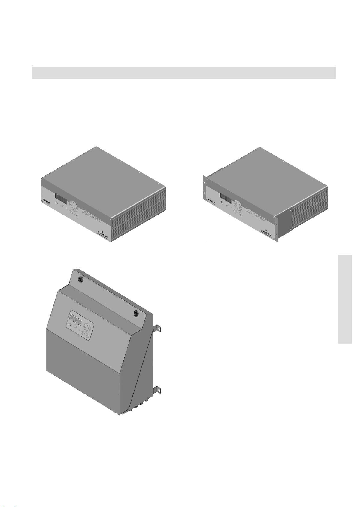
1-2 X-STREAM General Purpose
Tabletop or Rack Mount Version
Instruction Manual
HASAxE-IM-HS
05/2006
This basic general purpose version contains
all components within a full 19 inch housing and
is intended to either be used as rack mountable
analyzer or as tabletop instrument after removing
two mounting brackets and installing 4 feet (part
of an accessory kit).
The front panel shows a 4x20 characters alphanumeric display, a membrane keypad and
3 status LEDs (fig. 1-1).
Electrical connections are provided by either
screw terminals (version GP , fig. 1-2) or plugs,
sockets and mains appliance (version GPS,
fig. 1-3) at the instrument's rear side.
Gas fittings are provided at the instrument's
rear side, too.
An optional fitting facilitates purging the
instrument with inert gas to minimize influences
caused by ambient air when measuring low
ranges of select gases (e.g. CO, CO
). The in-
2
ert gas may exhaust the analyzer through a
separate fitting (into an exhaust system) or
by leakages in the housing (into ambient).
Purging the physical components with air or
inert gas may also be needed when measuring aggressive and/or flammable gases: In
addition to the purge fitting an internal box is
installed, covering the physical components.
This forces the purge medium to flow around
all other (electronic) components before it
circulates around the physics and exhausts
the analyzer through a separate outlet fitting
into an exhaust system. In case of internal
leakage this ensures that the aggressive/
flammable gas is not flushed towards the
electronics causing hazards of corrosion and/
or explosion and provides operator safety .
Purge medium specifications:
2-1, page 2-4.
1 3456 72
1 4x20 characters alphanumeric display
2 LED (red)
3 LED (red)
4 LED (green)
Fig. 1-1: X-STREAM GP, GPS, front side view
1-4 Emerson Process Management GmbH & Co. OHG
5 "Home" key
6 "Enter" key
7 4 keys for editing and entering menus
Page 27
Instruction Manual
HASAxE-IM-HS
05/2006
X-STREAM
1-2 X-STREAM GP, GPS
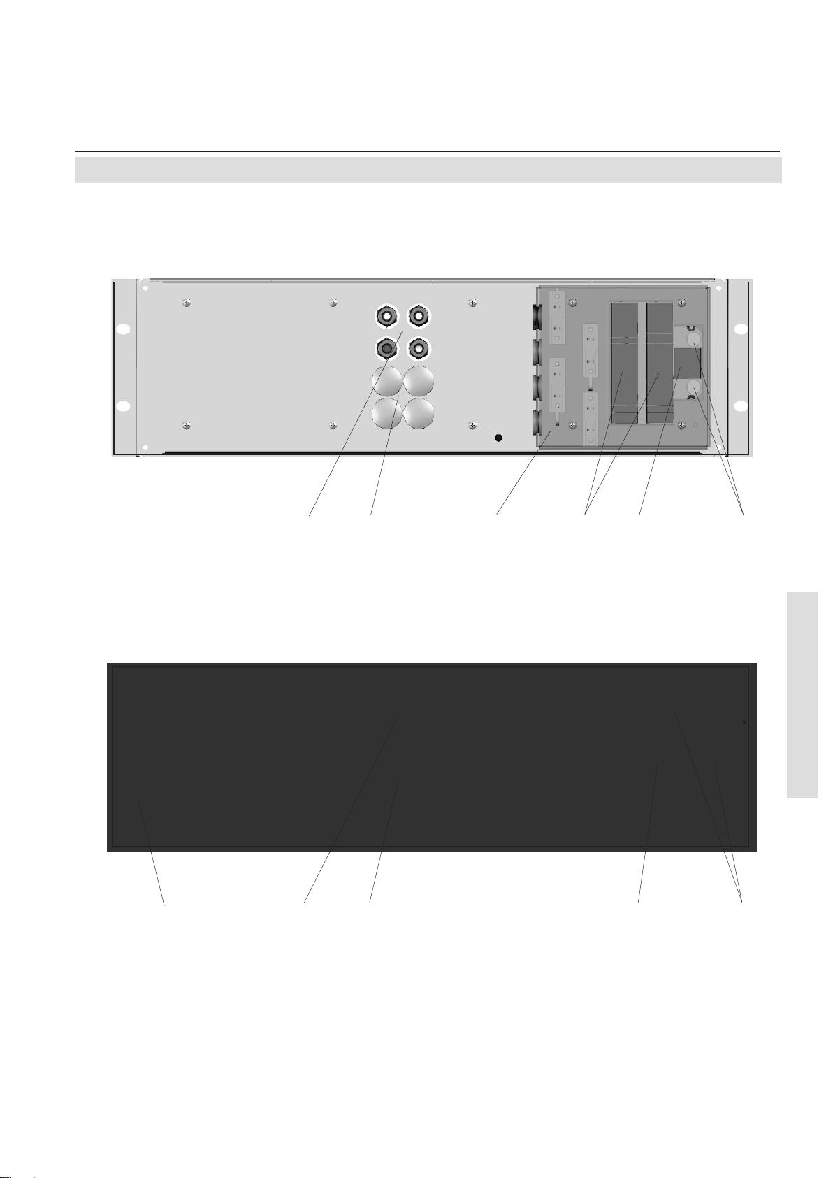
1 23456
1 Gas inlet fittings
2 Optional gas inlet fittings
3 Cover for terminals (shown with
transparency)
Fig. 1-2: X-STREAM GP, terminals version, rear side view
1 23 45
4 Input / output signal terminals
5 Mains terminals
6 Mains fuses
1 Technical Description
1 Gas inlet fittings
2 Optional gas inlet fittings
3 Optional purge gas inlet
Fig. 1-3: X-STREAM GPS, plugs and sockets version, rear side view
4 Mains appliance with fuses
5 Signals sockets
1-5Emerson Process ManagementGmbH & Co. OHG
Page 28

X-STREAM
1-3 X-STREAM F
1-3 X-STREAM F (Field Housing)
Instruction Manual
HASAxE-IM-HS
05/2006
This IP66 / NEMA 4X protected housing is
intended for outside wall mounting: The housing
(fig. 1-4) is made of painted stainless steel.
Gaskets protect against water and dust.
The front panel is located behind a safety glass
providing protection against mechanical impact
and shows a 4x20 characters alphanumeric
display and 3 status LEDs. The keypad as it is
used to operate the tabletop analyzer is replaced by sensor fields, operated with a magnetic tool (fig. 1-5).
Electrical connections are provided by internal
screw terminals, the cables enter the housing
via cable glands located at the instruments
bottom side (fig. 1-6).
Gas fittings are located at the instrument's
bottom side, too.
The front door opens vertically by 180° providing easy access to internal components.
Removing the hinge bolts even allows to
completely remove the front door.
inert gas may exhaust the analyzer through a
separate fitting (into an exhaust system) or by
leakages in the housing (into ambient).
Purging the physical components with air or
inert gas may also be needed when measuring aggressive and/or flammable gases: In
addition to the purge fitting an internal box is
installed, covering the physical components.
This forces the purge medium to flow around
all other (electronic) components before is
circulates around the physics and exhausts the
analyzer through a separate outlet fitting into
an exhaust system. In case of internal leakage
this ensures that the aggressive/flammable
gas is not flushed towards the electronics
causing hazards of corrosion and/or explosion
and provides operator safety .
Purge medium specifications:
see technical data section (2-1).
An optional fitting facilitates purging the
instrument with inert gas to minimize influences
caused by ambient air when measuring low
ranges of select gases (e.g. CO, CO2). The
Provided with an appropriate pressurization
system the X-STREAM F is suitable for installation in hazardous areas.
EXPLOSION HAZARD !
This instruction manual at hand does not deal with X-STREAM analyzers
intended to be used in hazardous areas!
Installation, startup and maintenance are described in detail in a separate
instruction manual, shipped together with each such analyzer, and are not
subject of this current instruction manual!
1-6 Emerson Process Management GmbH & Co. OHG
Page 29

Instruction Manual
HASAxE-IM-HS
05/2006
X-STREAM
1-3 X-STREAM F
Fig. 1-4: X-STREAM F, front side view & rear side view at carrying handle
HEAVY INSTRUMENT!
X-STREAM F
gas analyzers, designed for wall mounting and/or outdoor
installation may weigh up to 25 kg (57 lbs), depending on installed options!
The upper part of the front door is designed to work as a carrying handle,
see fig. 1-4.
Use two persons or a suitable lifting device to move or carry the instrument!
1 Technical Description
1-7Emerson Process ManagementGmbH & Co. OHG
Page 30
X-STREAM
Instruction Manual
HASAxE-IM-HS
05/2006
1-3 X-STREAM F
1 345672
1 4x20 characters alphanumeric display
2 LED (red)
3 LED (red)
4 LED (green)
Fig. 1-5: X-STREAM F, front panel
1-8 Emerson Process Management GmbH & Co. OHG
5 "Home" key
6 "Enter" key
7 4 keys for editing and entering menus
Page 31

Instruction Manual
HASAxE-IM-HS
05/2006
X-STREAM
1-3 X-STREAM F
2 134
1 Cable glands for mains and signal cables
2 Gas inlet and outlet fittings and purge gas outlet fitting
3 Purge gas inlet fitting
4 4 supports for wall mounting
Fig. 1-6: X-STREAM F, bottom view
1 Technical Description
1-9Emerson Process ManagementGmbH & Co. OHG
Page 32

X-STREAM
Instruction Manual
HASAxE-IM-HS
05/2006
1-3 X-STREAM F
1 423
1 Terminals for signal cables
2 Mains EMI filter
3 Cable glands for mains and signal cables
4 Mains terminals with integrated fuses
Fig. 1-7: X-STREAM F, mains and signal terminals (front door removed)
1-10 Emerson Process Management GmbH & Co. OHG
Page 33

Instruction Manual
HASAxE-IM-HS
05/2006
1-4 Reserved For Future Use
1-4 Reserved For Future Use
X-STREAM
1 Technical Description
1-11Emerson Process ManagementGmbH & Co. OHG
Page 34

X-STREAM
1-5 Gaspath Design
1-5 Gaspath Design
Various materials are available to provide a
best possible analyzer adaption to the application. Materials are selected taking into
account e.g. diffusion rate, corrosiveness,
temperature and pressure of the applied gas.
1-5-1 Gas Paths Materials
Physical and chemical characteristics of
applied gases and working conditions
(temperature and pressure) affect the available materials.
Instruction Manual
HASAxE-IM-HS
05/2006
1-5-2 Safety Filter
All analyzers provide an internal stainless steel
safety filter. This filter(s) is (are) not a substitute
for a dust filter to be installed in the sample
handling system!
1-5-3 Fittings
By default all analyzers are equipped with
PVDF fittings (ø 6/4 mm)
Alternatively Swagelok
®
or stainless steel
fittings(ø 6/4 mm or 1/4") or other fitting
materials (on request) may be used.
1-5-4 Piping
Analyzers are piped with Viton or PTFE
(ø 6/4 mm).
Other materials (e.g. stainless steel) are used
optionally , depending on application.
1-12 Emerson Process Management GmbH & Co. OHG
Page 35

Instruction Manual
HASAxE-IM-HS
05/2006
1-5-5 Gas Path Variations
X-STREAM
1-5 Gaspath Design
Depending on the application and the selected
options several gas paths configurations are
Analyzer
Gas inlet
(IN K1)
Fig. 1-8: Single channel or serial tubing
available, as shown in the following figures
(examples):
Gas outlet
(OUT K1)
Gas inlet
(IN K1)
Gas inlet
(IN K2)
Analyzer
Fig. 1-9: Dual channel parallel tubing
Gas outlet
(OUT K1)
1 Technical Description
Gas outlet
(OUT K2)
1-13Emerson Process ManagementGmbH & Co. OHG
Page 36

X-STREAM
V1
Instruction Manual
HASAxE-IM-HS
05/2006
1-5 Gaspath Design
Analyzer
V2
Sample gas
(V3)
V4
Solenoid
valves
(option)
Sample pump (option)
Fig. 1-10: Single channel or serial tubing, with options
Gas outlet
(OUT K1)
1-14 Emerson Process Management GmbH & Co. OHG
Page 37

Instruction Manual
HASAxE-IM-HS
05/2006
1-6 Optional Gas Path Components
1-6 Optional Gas Path Components
Optionally available for all analyzer variations
are:
• internal sample gas pump
• internal valve block
• internal flow monitor
• internal barometric pressure sensor
X-STREAM
1-6-1 Internal Sample Gas Pump
An optional sample gas pump may be required
if the process gas stream is without exerting
pressure. In this case the pump ensures the
sample gas stream through the instrument
remains constant.
If an internal sample gas pump is installed, the
associated software setup menu entry shows
Y es (
5-4-3-5, page 5-41). The valve may
be controlled either manually by a corresponding menu line or remotely by a digital input.
1-6-2 Internal Valve Block
An optional internal valve block allows to
directly connect sample gas as well as span
and zero calibration gases to the instrument,
e.g. enabling automatic calibration.
If an internal valve block is installed, the associated software setup menu entry shows
Internal or Int+Ext ( 5-4-3-5, page 5-41).
V alve control is supported by a corresponding
menu line, by selecting the autocal mode or
remotely by digital inputs.
1-6-3 Internal Flow Monitor
An optional internal flow meter allows to
monitor the gas flow and set an alarm in case
of a fault.
If an internal flow monitor is installed, the associated software setup menu entry shows Yes
(
5-4-3-5, page 5-41).
There will be a status message in the measuring screen if the gas flow is too low and the
related "Check requests" menu entry is Yes
( chapter 8 "Troubleshooting").
1-6-4 Internal Barometric Pressure Sensor
An optional internal barometric pressure
sensor allows to compensate the influence of
changing ambient pressure on the measuring
results.
If an internal pressure sensor is installed, the
associated software setup menu entry shows
Internal or Use ch2 ( 5-4-3-5, page 5-41).
1 Technical Description
1-15Emerson Process ManagementGmbH & Co. OHG
Page 38

X-STREAM
1-6 Optional Gas Path Components
1-6-5 Optional Heated Compartment
Instruction Manual
HASAxE-IM-HS
05/2006
Two optional internal heated compartments
offer three functionalities:
At first the compartments allow to heat all
physical components at 60° C to avoid
condensation of gases inside the gas path and/
or reduce influence of ambient temperature
fluctuation.
In addition to thermostating the physical components this box can be purged and thus allows
to keep out ambient air, interfering measuring
gases at low ranges. The purge medium is
applied to a separate fitting, passes the
electronics, enters the box and exits through
leaks into ambient.
An alternative, gastight compartment allows to
measure corrosive and toxic gases protecting
the electronics and providing operator safety .
With this box the purge medium when applied
to the separate inlet fitting flows through the
electronics, enters the box to flow around the
physical components and than exits through a
purge gas outlet, recommended to be
connected to an exhaust.
123
1 Fixed part
2 Removeable cover
Thermostated box, purgeable,
for low measuring ranges
Fig. 1-12: Optional Heated Compartment
1-16 Emerson Process Management GmbH & Co. OHG
213
3 Cable feed throughs
4 Detent springs
Thermostated box, purgeable,
for measuring corrosive / toxic gases
4
Page 39

Instruction Manual
HASAxE-IM-HS
05/2006
1-7 Interfaces
X-STREAM
1-7 Standard Interfaces
All models are configured to provide the following interfaces:
• analog outputs
• Modbus interface (RS 485 / RS 232)
• status signals (NAMUR; relay outputs)
1-7-1 Analog Outputs
The results of each measuring channel are
output via a current output.
By means of a software setup menu the outputs can be configured to support a variety of
operating modes (e.g. 0-20 mA, 4-20 mA) as
1-7-2 Modbus Interface
The analyzers are equipped with a serial
interface supporting Modbus RTU protocol to
provide communication with external hosts
(e.g. data acquistition systems). The interface
supports parameter data transmission, changing of parameters and initializing functions
(procedures).
The RS 485 interface is optically isolated from
the analyzer electronics and allows to build up
a network of several analyzers.
Digital inputs/outputs are optionally available.
The interface signals are provided at a submind-connectors or screw terminals, depending on
analyzer model.
well as the NAMUR NE 43 specifications
( 5-4-3-4-1, page 5-34).
Factory default settings for analog outputs are
4-20 mA.
Optionally available is a RS232 interface with
or without optical isolation against analyzer
electronics.
Read the instructions in the technical data
section of your analyzer variation carefully
to obtain failure-free data communication
(
2-2, page 2-5 et sqq.)!
Refer to chapter 9 for information about
available Modbus commands.
1 Technical Description
1-7-3 Status Signals (NAMUR)
Three relay status outputs are available to
digitally monitor the analyzer status according
the NAMUR NE107 specification: "Failure",
"Maintenance required / Off specification" and
"Function check".
The status relays provide dry contacts with a
maximum load of 30 V / 1 A / 30 W each!
The operation mode (NO "normally open" /
NC "normally closed") is NOT user configurable
and by default is factory set to NO. Other
settings need to be defined at time of placing
the analyzer order.
Refer to the technical data section of your
analyzer variation for a more detailled information about relay status signals (
2-2,
page 2-5 et sqq.)!
1-17Emerson Process ManagementGmbH & Co. OHG
Page 40

X-STREAM
1-8 Optional Interfaces
Instruction Manual
HASAxE-IM-HS
05/2006
1-8 Optional Interfaces
Optionally available are the following interfaces
(in combination only):
• 8 digital outputs
• 7 digital inputs
1-8-1 Digital Outputs
Digital outputs are required for reporting concentration alarms to external systems (e.g. data
aquisition systems) and/or for controlling
external valves (e.g. for automatic calibration).
Digital outputs are "open collector" outputs,
optically isolated against the instrument's
electronics. Outputs are not protected against
short circuits.
Electrical data
U < 30 V dc
I < 30 mA dc
Remaining voltage when activated: < 2 V
Common GND ( - ) for all outputs.
The interface signals are provided at submind-connectors or screw terminals, depending on
analyzer model.
Out 1
load
Out 2
load
Inside analyzer Outside analyzer
"+" and "GND" from external power supply
Fig. 1-13: Digital Outputs - Schematic
1-8-2 Digital Inputs
Digital inputs are required for remotely starting
calibration proceduresor activating valves or
the optional internal pump by simply supplying
a voltage.
Electrical data
LOW: U
< 1.5 V
in
HIGH: Uin > 4.5 V
Input resistance: 57.5 kΩ
(V oltages to be measured against the reference
terminal labeled "IN GND").
Inputs protected against overvoltage up to
approx. 40 V . Open inputs are at LOW level.
1-18 Emerson Process Management GmbH & Co. OHG
Page 41

Instruction Manual
HASAxE-IM-HS
05/2006
1-8 Optional Interfaces
1-8-2-1 Remotely Activating a Calibration
Procedure using IN 1 to IN 3
Use IN 1 to start a zero calibration, IN 2 for
channel 1 span calibration and IN 3 for channel 2
span calibration.
The related calibration procedure is activated
by a rising signal edge ending in a HIGH signal
of min. 2 sec. duration. Once started the
calibration keeps ongoing even if the signal
returns to LOW state.
X-STREAM
Additional trigger signals applied to other inputs
during an ongoing calibration are considered
only, if the HIGH signal is still applied for at
minimum 1 second when the ongoing
calibration ends. Otherwise this additional
trigger is rejected.
Simultaneous signals on multiple inputs are
considered according their priorities in the
sequence IN 1 - IN 2 - IN 3.
Example 1:
Input A activates a zero calibration.
Input B starts during the zero calibration. Because it ends minimum 1 sec after zero calibration ends, the related
ch2 span calibration is started.
Input C is rejected because it has ended BEFORE the ongoing ch2 span calibraton ends.
Example 2:
Inputs E and F start at the same time: F is rejected because of the lower priority in the sequence IN 1 - IN 2 - IN 3.
Fig. 1-14: Digital Inputs - Priorities
1-19Emerson Process ManagementGmbH & Co. OHG
1 Technical Description
Page 42

X-STREAM
Instruction Manual
HASAxE-IM-HS
05/2006
1-8 Optional Interfaces
1-8-2-2 Valve Control
Inputs IN4 to IN7 are evaluated in decreasing
order of priority: highest priority within this group
is assigned to IN4, lowest priority to IN7.
Applying a HIGH signal to an input while all
inputs of higher priority are at LOW level opens
the associated valve and closes all other valves,
regardless of the inputs of lower priority .
IN7 has a converted input logic: applying a
LOW signal opens valve V3; a HIGH level
signal closes ALL valves.
Action / Input IN4 IN5 IN6
Op en val ve V4 HXXX
Op en val ve V1 LHXX
Op en val ve V2 LLHX
Open sample gas valve LLLL
Close all val ves LLLH
H: HIGH
L: LOW
X: don't care
Table 1-1: Digital Inputs IN4-IN7, array
IN7
1-8-2-3 Remote Pump Control
Input IN7 may be used to control the optional
internal sample gas pump: applying a LOW
signal switches on the pump, a HIGH level
signal switches off.
Pump control depends on the IN7 input only
and is independent of inputs IN1 to IN6!
Note!
Pump control via digital input IN7 requires the
parameter "PumpControl" in the IN/OUTPUTS SETUP menu set to Remote (
5-4-3-4, page 5-33)
1-20 Emerson Process Management GmbH & Co. OHG
Page 43

Instruction Manual
HASAxE-IM-HS
05/2006
Chapter 2
Technical Data
This chapter lists all the analyzers technical
data, separated into common and model
specific data, therefore the user has to select
the appropriate section depending on his
analyzer.
Common Technical Data Page 2-2
X-STREAM
X-STREAM GP, X-STREAM GPS Page 2-5
X-STREAM F Page 2-10
Emerson Process Management GmbH & Co. OHG
2 Technical Data
2-1
Page 44

Instruction Manual
X-STREAM
HASAxE-IM-HS
05/2006
2-1 Common Technical Data
2-1 Common Technical Data
Site of installation
Humidit y (non cond ensin g) < 90 % r. h. at 68 F (+20 °C)
< 70 % r. h. at 104 F (+40 °C)
Pollution degree 2
Installation category I I
Altitude 0 to 6560 ft (2000 m) above sea level
Sourrounding atmosphere Analyzers must not be operated in hazar-
dous or flammable atmoshere without
additional safety measures.
Analyzers must not be operated in
corrosive atmoshere.
Compliances
Electrical safety CAN / USA CSA-C/US, based on
CAN/CSA-C22.2 No. 61010-1-04 /
UL 61010-1, 2nd Edition
Europe CE, based on EN 61010-1
Electromagnetic compatibility
Europe CE, based on EN 61326
Australia C-Tick
other NAMUR
Power supply
Rated input voltage 100 - 240 V
50/60 Hz, wide range input
Power supply voltage fluctuations are
not to exceed +/- 10 % of the nominal
supply voltage!
Input voltage range 85 - 264 V , 47 - 63 Hz
Rated input current
standard 0,75 - 0,35 A max.
with thermostated physics 2 - 1 A max.
2-2
Emerson Process Management GmbH & Co. OHG
Page 45

Instruction Manual
HASAxE-IM-HS
05/2006
X-STREAM
2-1 Common Technical Data
Interfaces, signal inputs / outputs
2 analog outputs channel 4 (0) - 20 mA (RB < 500 Ω)
(optically isolated; configurable by keypad
start and end concentration user configurable)
Modbus interface RS 485 (2- or 4-wire)
optional RS 232
with or without optical isolation
3 relay outputs (option "status signals“) “Failure”
according NAMUR NE 107 “Maintenance required / Off specification"
“Function check”
dry contact s, max. 30 V; 1 A; 30 W resistive
Digital Inputs and Outputs (option)
7 digital inputs zero calibration ch1 & ch2,
(common ground) span calibration ch1,
span calibration ch2,
open valve V4
open valve V1
open valve V2
open sample gas valve V3 /
switch off sample pump
max. 30 V , internally limited to 2.3 mA
H level: min. 4 V; L level: max. 3 V
8 digital outputs 2 thresholds per channel,
(optically isolated, common ground) sample gas valve,
zero gas valve V4,
span gas valve V1,
span gas valve V2
“Open Collector”, max. 30 V
/ 30 mA
Emerson Process Management GmbH & Co. OHG
2 Technical Data
2-3
Page 46

X-STREAM
Gas parameters
Chapter 3 Measuring Principles
Purge Option
Instruction Manual
HASAxE-IM-HS
05/2006
2-1 Common Technical Data
Purge medium (e.g. for minimizing CO
inter-
2
ference, safety in events of internal leakage of
flammable or/and aggressive gas etc.) must
be dry, clean and free of corrosive and
solvent components and on ambient
temperature (at least 68...95 F / 20...35 °C) !
For pressure and flow specification consult
factory or your local EMERSON Process Management sales office!
2-4
Emerson Process Management GmbH & Co. OHG
Page 47

Instruction Manual
HASAxE-IM-HS
05/2006
2-2 Model Specific Technical Data
2-2 Model Specific Technical Data
2-2-1 X-STREAM GP, GPS
Tabletop or
Rack Mount Version
X-STREAM
Fig. 2-1: X-STREAM GP, GPS - dimensions [approx. mm (inch)]
Emerson Process Management GmbH & Co. OHG
2 Technical Data
2-5
Page 48

Instruction Manual
X-STREAM
HASAxE-IM-HS
2-2-1 X-STREAM GP, X-STREAM GPS
Housing
Permissible ambient temperature range 32 F to 122 F ( 0 °C to +50 °C)
Weight: approx. 26.5 to 35.3 lbs (12 - 16 kg)
(depending on analyzer configuration)
Protection class to EN 60529: IP 20 for indoor installation
Analyzer must not be exposed to dripping
or sprayed water.
Gas fittings: quantity: max. 4
specification: 6/4 mm PVDF
optional 6/4 mm or 1/4", stainless
steel, other on request
05/2006
2-2-1-1 Terminals Version
Power connection
Connection via covered screw terminals located
at the analyzer's rear panel (fig. 2-2).
Cross section: max. 12 A WG (2.5 mm
2
), using conductor
sleeves is not required
Cable entry through cover via 1 strain relief
Power fuses
Two fuses are located nearby the power terminals.
Fuse ratings: AC 230 V, 3.15 A, 5x20 mm
2-6
Emerson Process Management GmbH & Co. OHG
Page 49

Instruction Manual
HASAxE-IM-HS
05/2006
X-STREAM
2-2-1 X-STREAM GP, X-STREAM GPS
Line
PE
Neutral
64 3125
1 Fuse holders
2 Power terminals
3 Signal terminals
Fig. 2-2: X-STREAM GP, (terminals version) -
terminals and fuse holders (cover removed)
4 S train reliefs
5 Protective earth terminal (PE)
6 Edge protection (part of removed cover;
shown for demonstration only)
Signal inputs / outputs
All signal lines need to be connected to screw
terminals located at the analyzer‘s rear panel.
Available signals: standard: Analog signal outputs
Relay status signals
Modbus interface (RS232; RS 485)
optional: Digital inputs/outputs
Detailed pin assignment
4-4 Installation, page 4-6.
2 Technical Data
Emerson Process Management GmbH & Co. OHG
2-7
Page 50

Instruction Manual
X-STREAM
2-2-1 X-STREAM GP, X-STREAM GPS
2-2-1-2 Sockets Version
Power Connection
Connection via IEC power appliance, provided
at the analyzer's rear panel (fig. 2-3).
Power fuses
T wo fuses are located in the power appliance.
Fuse ratings: AC 230 V, 3.15 A, 5x20 mm
HASAxE-IM-HS
05/2006
2
3
1
1 Power appliance with EMI filter
2 Signal sockets/plugs
Fig. 2-3: X-STREAM GPS, (sockets version) -
power and signals connectors
3 Fuse holder
2-8
Emerson Process Management GmbH & Co. OHG
Page 51

Instruction Manual
HASAxE-IM-HS
05/2006
2-2-1 X-STREAM GP, X-STREAM GPS
Signal inputs / outputs
All signal lines need to be connected to 9 pole
and 25 pole submin-D-plugs and sockets,
located at the analyzer‘s rear panel (fig. 2-3).
Available signals: standard: Analog signal outputs
Relay status signals
Modbus interface (RS232; RS 485)
optional: Digital inputs/outputs
X-STREAM
Detailed pin assignment
4-4 Installation, page 4-6.
Emerson Process Management GmbH & Co. OHG
2 Technical Data
2-9
Page 52

X-STREAM
Instruction Manual
HASAxE-IM-HS
05/2006
2-2-2 X-STREAM F
2-2-2 X-STREAM
F Field Housing
Fig. 2-4: X-STREAM F - dimensions (approx. mm [inch])
Housing
Permissible ambient temperature range -4 F to 122 F ( -20 °C to +50 °C)
Weight: approx. up to 57.3 lbs (26 kg)
(depending on analyzer configuration)
Protection class: IP 66 (EN 60529) / NEMA 4X
for outdoor installation
Analyzer must not be exposed to direct
sun light
Gas fittings: quantity: max. 8
specification: 6/4 mm PVDF
optional 6/4 mm or 1/4", stainless
steel, other on request
2-10
Emerson Process Management GmbH & Co. OHG
Page 53

Instruction Manual
HASAxE-IM-HS
05/2006
X-STREAM
2-2-2 X-STREAM F
Power Connection
Connection via internal screw terminals near
cable glands, (fig. 2-6).
Cross section: max. 10 A WG (4 mm2), using conductor
sleeves is not required
Cable entry via 1 cable gland, classified IP 68
Permissible outer cable diameter for power cable: 0.28 to 0.5 inch (7 - 12 mm)
Power fuses
The power terminals integrate fuse holders.
Fuse ratings: AC 230 V, 3.15 A, 5x20 mm
1 Power terminals with integrated
fuse holders
2 Protective earth terminal (PE)
Fig. 2-5: X-STREAM F - power terminals / fuse holders
Emerson Process Management GmbH & Co. OHG
3 24 1
3 Power cable gland
4 EMI power filter
2 Technical Data
2-11
Page 54

Instruction Manual
X-STREAM
HASAxE-IM-HS
2-2-2 X-STREAM F
Signal inputs / outputs
All signal lines need to be connected to internal
screw terminals (fig. 2-7)
Cross section: max. 12 A WG (2.5 mm
2
), using conductor
sleeves isnot required
Cable entry via 3 cable glands, classified IP 68
Permissible outer cable diameter for power cable: 0.28 to 0.5 inch (7 - 12 mm)
Available signals: standard: Analog signal outputs
Relay status signals
Modbus interface (RS485; RS 232)
optional: Digital inputs/outputs
05/2006
Detailed pin assignment
4-4 Installation, page 4-6.
Fig. 2-6: X-STREAM F - signals terminals
2-12
Emerson Process Management GmbH & Co. OHG
Page 55

Instruction Manual
HASAxE-IM-HS
05/2006
2-3 Specifications on the Nameplate Label
2-3 Information on the Nameplate Label
X-STREAM
The analyzer nameplate label gives important
information about the instrument‘s configuration, installed measuring principle(s),
sample gas(es), measuring range(s) and
shows the serial number, required when asking
for support or spare parts.
Model and installed measuring
principles (here: IR & UV)
Channel 1:
Gas and measuring range
(here: CO, 400 to 1000 ppm)
Fig. 2-7: Analyzer Nameplate Label (example)
The nameplate label is located either on the
instruments left or right housing side or at the
inner side of the front door (field housing).
Serial number
Channel 2:
Gas and measuring range
(here: SO2, 800 to 2000 ppm)
Note!
The operator may change the analog output
scaling within the stated measuring ranges
without affecting the specifications.
(Here for channel 1 a 20 mA output signal
may be assigned to concentration values
between 400 and 1000 ppm, ANALOG
OUTPUT SIGNAL SCALING menu, page
5-35 ).
The measuring ranges are also shown in the
INFO - RANGES.. menu, page 5-57.
Emerson Process Management GmbH & Co. OHG
2 Technical Data
2-13
Page 56

X-STREAM
Instruction Manual
HASAxE-IM-HS
05/2006
2-14
Emerson Process Management GmbH & Co. OHG
Page 57

Instruction Manual
HASAxE-IM-HS
05/2006
X-STREAM
Chapter 3
Measuring Principles
X-STREAM
series analyzers support several
measuring principles or combinations of
principles, depending on measured gas
components. This provides best possible
results as the principle always is adjusted to
meet the specific characteristics of the
particular gas.
The following sections introduce the available
measuring principles and show their specific
characteristics.
3-1 Infrared Measurement (IR)
Ultraviolet Measurement (UV)
This principles make use of infrared/ultraviolet
light absorbed by the sample gas. The wave
length of the absorbed portion of IR/UV light
characterizes the gas component whereas the
intensity of absorption is a measure of
concentration.
Two different IR measuring principles are
available, both comparing concentration
depend and concentration independ signals.
The difference of these two signals results in a
measure of concentration.
One of these principles (as described in detail
in the following sections) is adapted for UV
measurements: The absorption measurement
in the UV spectral range is based on the same
principle as the IR measurement, but a glowdischarge source is used instead of an IR
source.
As the glow-discharge source needs a specific
and as constant as possible temperature, it is
either thermostatted to about 55 °C or built into
a thermostatted box, covering all physical
components and completely thermostatted.
Section 3-1-2 covers both IR and UV measurement.
The decision about which measurement (UV
or IR) is selected for a specific application
depends on the gas component to be
measured. The decision about which IR
measurement to be used is based on the
required performance.
3-1-1 Interference Filter Correlation (IFC)
This is an IR principle only and suitable for
applications not requiring high performance
parameters.
An undivided analysis cell is alternately passed
by light of two different wave lengths, filtered
by interference filter out of the spectrum of an
IR source: One wavelength covers the
absorption band of the measured gas
component, the other is selected to cover a
region where no absorption occures.
Fig. 3-1 shows an example of interference filter
transmissions and absorption bands of the gas
components CO and CO
. It‘s easy to see that
2
the interference filters‘ transmissible spectral
bands overlap the absorption bands of the
gases, whereas within the bandwidth of the
reference filter no absorptin takes place. Other
gases (CH4) and HC do not affect the measuring result because they do not absorb IR light
of these wavelengths.
3 Principles
Emerson Process Management GmbH & Co. OHG
3-1
Page 58

X-STREAM
Instruction Manual
HASAxE-IM-HS
05/2006
3-1 Infrared (IR) and Ultraviolet (UV) Measurement
CO
Fig. 3-1: Absorption Bands of Measured Gases and
Transmission of Interference Filters
A pyroelectrical detector generates a signal
using the effect of charge flow caused by heat
flow within a piezo crystal:
The IR radiation passing measuring cell and
filters results in a change of temperature when
arriving at the detector. The IR absorption is
different for measuring wavelength and
reference wavelength so the crystal is
alternately more or less heated. As result the
detector gives an alternating voltage signal
which is passed to electronics for further
processing.
CO
2
3-2
Emerson Process Management GmbH & Co. OHG
Page 59

Instruction Manual
HASAxE-IM-HS
05/2006
3-1 Infrared (IR) and Ultraviolet (UV) Measurement
3-1-2 Opto Pneumatic Measuring Principle
X-STREAM
This high performance principle is used for IR
and UV measurements and utilizes a separated
analysis cell whose one side is passed by the
sample gas. The other side (reference side) is
either filled with an inert gas (e.g. nitrogen) or
passed by a reference gas stream, depending
on application.
Both sides of the cell are alternately irradiated
with IR (UV) light of same intensity, which
afterwards passes a filtering cell before it
arrives at the detector.
absorption chamber
The opto pneumatical detector, which is used
instead of the pyroelectrical detector with the
IFC principle, converts the radiation from sample side and reference side into a voltage
signal proportional to the radiation intensity .
The pneumatical detector consists of a gas
filled absorption chamber and a compensation
chamber, both connected by a flow channel. A
micro flow detector is placed within this channel
to measure least flows.
CaF2 window
gas filler
3 Principles
flow channel
with
micro flow detector
Fig. 3-2: Gas Detector Design Principle
Emerson Process Management GmbH & Co. OHG
compensation chamber
3-3
Page 60

X-STREAM
Instruction Manual
HASAxE-IM-HS
05/2006
3-1 Infrared (IR) and Ultraviolet (UV) Measurement
3-1-3 Technical Implementation
The detector is filled with the gas to be
measured and therefore sensitive to the related
characteristic wavelength band only .
The absorption chamber is sealed with a
window transparent for IR radiation [CaF
(Calziumfluorid)] .
There is no absorption when the IR(UV)
radiation passes the reference side of the
analysis cell , so the intensityis at a maximum
when it arrives at the detector. The gas within
the detector is heated, therefore expands and
flows from absorption chamber through flow
channel to the compensation chamber. This
flow generates a voltage signal.
When the IR(UV) radiation passes the sample
side of the analysis cell, part of it is absorbed
by the sample gas decreasing the radiation
intensity . As an effect the gas within the detector
cools down and flows from the compensatoin
chamber back into the absorption chamber.
This flow again causes a voltage signal by the
micro flow detector which is now reverse to the
previous signal.
So the micro flow detector generates alternating signals. The flow channel is designed to
not influence the gas flow and therefore the
change in signal is proportional to the change
in radiation intensity which is proportional to
the concentration of gas to be measured.
The broadband IR (UV) radiation emitted by a
special source passes a chopper wheel (fig.
3-3 showing a dual channel analyzer). In case
of IFC principle it passes additional optical
filters, before entering the analysis cell. The
2
radiation leaving the cell is focused to the
detector by means of a filter cell. The detector
output signal is passed to micro processor
controlled electronics conditioning and
converting it to reasonable units (V ol-%, ppm,
mg/m³, etc.) shown on the alphanumeric
display.
Depending on gas component and measuring
range several photometer designs are used
with X-STREAM series analyzers, differing in
analysis cell length, kind of detector and used
filters. Optionally the assemby may be sealed
against ambience: O-rings between the
components prevent ambient air to come in the
optical path and interfere the measurement.
The photometer assembly is mounted on the
BKS main board, which itself is placed in
housings rail.
The flow detector signal is passed to electronics conditioning the signal and converting
it into a usefull format.
3-4
Emerson Process Management GmbH & Co. OHG
Page 61
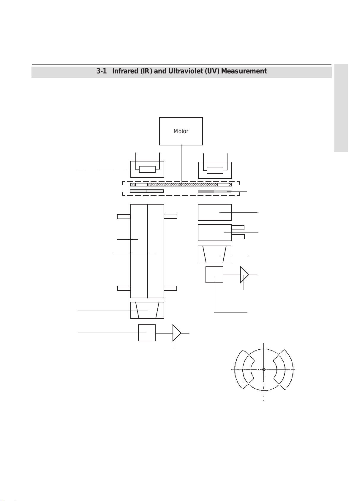
Instruction Manual
HASAxE-IM-HS
05/2006
X-STREAM
3-1 Infrared (IR) and Ultraviolet (UV) Measurement
IR source
or
UV source
Analysis cell, sample side
Analysis cell, reference side
Motor
3 Principles
Filter
Adaptor cell
(High measuring ranges)
Analysis cell
(undivided)
Filter cell
Preamplifier
Filter cell
Gas detector
Fig. 3-3: IR Photometer Assembly Principle,
left side: with Gas Detector, right side: with Pyro Electrical Detector
Emerson Process Management GmbH & Co. OHG
Pyroelectrical detector
(solid state detector)
Preamplifier
Chopper wheel
3-5
Page 62

X-STREAM
3-1 Infrared (IR) and Ultraviolet (UV) Measurement
Photometer Assembly with Pyro Detector
Instruction Manual
HASAxE-IM-HS
05/2006
Fig. 3-4 shows the mechanical design of an
pyro detector assembly:
Attached to the chopper are IR source (07) as
well as analysis cell (09) with signal detector
unit (filter cell 14 / 15) and pyroelectrical
detector with integrated pre amplifier (16).
Furthermore the chopper assembly contains
the filter aperture (04 / 05) limiting the IR light
to the required bandwidth.
The chopper assembly (03) is made of two
parts and contains an inner volume where the
stepper motor driven chopper wheel is placed.
This inner volume is sealed against ambience
by means of an o-ring to prevent ambient CO
from entering. This avoids pre absorption and
drift. An additional absorber is used to remove
CO2 traces existent by diffusion.
Furthermore the chopper assembly contains a
light barrier to detect the chopper wheel
phasing. A temperature sensor (28) measures
the assemblies‘ temperature. This information
is used for the purpose of compensating
temperature effects.
The filter cell (14 / 15) is made as two-tiered
conus system, which is optimized to focus the
beam to the active detector area.
High measuring ranges (up to 100 %) require
an adaptor cell (10): The analysis cell is in this
case the volume between output window of the
adaptor cell and input window of the filter cell ,
covered by a distance ring (08).
2
The analysis cell is made of an aluminum tube
with two gas fittings. This simple design without
windows easily allows cleaning if the cell is
polluted.
The chopper windows and those at the filter
cell remain as only possibly polluted windows.
All of them are accessible once the analysis
cell is removed.
3-6
Emerson Process Management GmbH & Co. OHG
Page 63

Instruction Manual
HASAxE-IM-HS
05/2006
X-STREAM
3-1 Infrared (IR) and Ultraviolet (UV) Measurement
07
3 Principles
03 Chopper
04 / 05 Filter aperture
06 Zero aperture (not with sealed variation)
07 Source
08 Analysis cell 1 - 7 mm (distance ring)
09 Analysis cell 50 - 200 mm
10 Adaptor cell
14/15 Filter cell
16 Detector
Fig. 3-4: Photometer Assembly with Pyroelectrical Detector
Emerson Process Management GmbH & Co. OHG
17 Flange (source)
18-21 O-ring
22 Clamp (for cells 1-7 mm)
23 (24) Clamp (for cells 1-7 mm)
25 Clamp (for cells10-200 mm)
26 Fixing screws (source)
27 Fixing screws (cells and adaptor cells)
28 T emperature sensor
3-7
Page 64

X-STREAM
3-1 Infrared (IR) and Ultraviolet (UV) Measurement
Photometer Assembly with Gas Detector
Instruction Manual
HASAxE-IM-HS
05/2006
The design of a gas detector photometer
assembly is on principle similiar to the pyro
detector design.
One main difference is the analysis cell, that
now is lengthwise divided and both ends
sealed with windows. This separates the inner volume into a sample side and a reference
side. The sample side is passed by the sample
gas, while the reference side is either filled with
air, neutral gas or reference gas, depending
on the application.
Variation 1 Variation 2
T o avoid erroneous measurements absorbers
may be installed at the reference side to
suppress interfering CO
traces (IR only).
2
The filter cell is made as single-tier conus
system.
The gas detector has separated preamplifier
electronics, to which it is connected by a
shielded cable.
For lower measuring ranges(long analysis cells)
the preamplifier is fixed onto the analysis cell,
whereas for higher ranges it is mounted on a
special cover plate
1 IR source
2 UV source
3 Analysis cells
3-8
1235 4
4 Chopper
5 Detectors
6 Preamplifier
Fig. 3-5: IR & UV Photometer Assemblies with Gas Detectors
35 46
Emerson Process Management GmbH & Co. OHG
1
2
Page 65

Instruction Manual
HASAxE-IM-HS
05/2006
3-2 Oxygen Measurement
X-STREAM
3-2 Oxygen Measurement
Two dif ferent principles are used for measuring
oxygen concentrations. The currently used
principle is given by the channel code (sample
gas designator) on the nameplate label (
fig 2-7, page 2-13):
pO2 = paramagnetical sensor
eO2 = electrochemical sensor
3-2-1 Paramagnetic Measurement
Oxygen measurement is based on the paramagnetical characteristics of oxygen molecules:
Two nitrogen filled quartz spheres (N2 is not
paramagnetic) are arranged in a dumbbell
configuration and, hinged to a platinum wire,
placed inside a cell. Fixed to the wire a small
mirror reflects a light beam to a photo detector
(fig. 3-6).
The measuring cell is placed inside an
inhomogeneous magnetical field generated by
a strong permanent magnet of specific design.
So the current compensating the torque affecting the dumbbell is a direct measure for the
oxygen concentration within the sample gas.
In addition to measuring cell, permanent
magnet, electronics and enclosure the paramagnetic oxygen detector contains a temperature sensor and a heating element to hold the
detector at approx. 55 °C.
Several variations are available including
corrosion resistant, solvent resistant and/or
intrinsically safe (for measuring flammable
gases) versions.
3 Principles
Oxygen molecules within the sample gas now
due to their paramagnetical characteristics are
deflected into the area of highest field strength.
This generates different forces on both spheres
and the resulting torque turns dumbbell and
mirror out of the rest position. This generates
a photodetector signal because the beam is
deflected, too.
Initiated by the photodetector signal a preamplifier drives a compensation current through
a loop surrounding the dumbbell to turn back
the dumbbell into the rest position by effect of
a magnetic field
Emerson Process Management GmbH & Co. OHG
Table 3-1: Solvent Resistant Sensor:
Approved Solvents
3-9
Page 66

X-STREAM
Instruction Manual
HASAxE-IM-HS
05/2006
3-2 Oxygen Measurement
10
415 368
11 7 9
2
1 Permanentmagnet
2 Platinum wire
3 Mirror
4 Glass ball
5 Loop
Fig. 3-6: Paramagnetic Oxygen Detector,
Assembly Principle
3-10
6 Photodetector
7 Light source
8 Preamplifier
9 Display
10 Gas inlet
11 Gas outlet
Table 3-2: Medium affected Materials within
Paramagnetic Oxygen Sensor
Emerson Process Management GmbH & Co. OHG
Page 67

Instruction Manual
HASAxE-IM-HS
05/2006
3-2 Oxygen Measurement
3-2-2 Electrochemical Measurement
X-STREAM
This sensor uses the principle of galvanic cells,
fig. 3-7 shows the design.
11
11
5
7
13
2
4
8
12
12
1 Anode (lead)
2 Kathode (Gold)
3 Electrolyte solution
4 Membrane
5 Thermistor
6 Resistance
7 Titanum wire
8 O-Ring
9 Pressure compensating volumes
10 Lid
11 Electrical connections
12 Lids
13 Current collector
10
6
9
3
1
The electrochemical oxygen sensor‘s key
components are a lead anode (1) and a gold
cathode (2) surrounded by a special acid
electrolyte (3).
The gold electrode is integrated solid with the
membrane,which is a non-porous fluororesin
membrane. Oxygen which barely diffuses
through the membrane is electrochemically
reduced on the gold electrode.
The temperature compensating thermistor and
adjusting resistance are connected between
the cathode and anode. The current generated
by oxygen reduction is converted into a voltage
by these resistances.
The value of the current flowing to the thermistor
and resistance varies in proportion to the
oxygen concentration of the measuring gases
which contact the membrane. Therefore, the
voltage at the terminal of the resistances is
used for the sensor output to measure the
oxygen concentration.
3 Principles
Fig. 3-7: Electrochemical Sensor
Assembly Principle
Emerson Process Management GmbH & Co. OHG
3-11
Page 68

X-STREAM
Instruction Manual
HASAxE-IM-HS
05/2006
3-2 Oxygen Measurement
(red) (black)
(11)
Thermistor (5)
(-)
Gold
cathode (2)
O2 + 4 H+ + 4 e- 2 H2O
Electrolyte (3)
Electrochemical reaction: O2 + 2 Pb 2 PbO
Fig. 3-8: Electrochemical reaction of Oxygen Sensor
Resistance (6)
Lead
anode (1)
2 Pb + 2 H2O 2 PbO + 4 H+ + 4 e
⎝
(+)
-
In consequence of it‘s design the sensor‘s
lifetime is limited and depends on theoretical
designed life and oxygen concentration. The
sensor output can be taken as a rough criterion
for end of lifetime: The sensor is weared when
the output in atmosphere is below 70 % of the
initial output. The period till this can be
calculated by
Lifetime =
designed life (hours)
O2 concentration (%)
The sensor‘s designed life under constant
conditions of 20 °C is approx. 900,000 hrs.
The lifetime at 21 % oxygen is then calculated
to approx. 42,857 hrs, corresponding to
approx. 5 years.
3-12
Note!
The given values are for reference only! The
expected lifetime is greatly affected by the
temperature of the environment in which the
sensor is used or stored. Increases or
decreases in atmospheric pressure have the
same effect as that by increases or decreases
in oxygen concentration (Operation at 40 °C
halves lifetime).
Emerson Process Management GmbH & Co. OHG
Page 69

Instruction Manual
HASAxE-IM-HS
05/2006
3-2 Oxygen Measurement
3-2-3 Special Hints on Oxygen Sensors
X-STREAM
Paramagnetic Sensor
The table below shows how accompanying
gases interfere the paramagnetical oxygen
measurement.
If the concentration of such gases is already
given at time of enquiry this interference may
be taken into account during factory startup and
thus minimized (option).
gas free of oxygen could result in a reversible
detuning of O
sensitivity . The output signal will
2
become unstable, but response time remains
constant.
For correct measurement the cell needs continuously to be supplied with concentrations of at
least 0.1 Vol.-% O2 . We recommend to use
the cells if need be in alternating mode, means
to purge cells with conditioned (not dried, but
dust removed) ambient air when measurement
pauses.
If it is necessary to interrupt oxygen supply for
several hours or days, the cell has to regenerate
(supply cell for about one day with ambient air).
Temporary flushing with nitrogen (N2) for less
than 1 h (e.g. for analyzer zeroing purpose) has
no influence on measuring characteristics.
This sensor is not suitable for anorganic gases
containing chlorene or flourene!
In addition is not suitable for sample gases
containing ozone, H2S (> 100 ppm) or
NH3 (> 20 ppm).
3 Principles
Table 3-3: Paramagnetic Oxygen Measurement,
cross interference by accompanying gases
Electrochemical Sensor
Due to the measuring principle the electrochemical oxygen cell requires a minimum
internal consumption of oxygen (residual
humidity avoids drying of the cell). Supplying
cells continuously with dry sample gas of low
grade oxygen concentration or with sample
Emerson Process Management GmbH & Co. OHG
For a number of other interfering gases see
table 4-3 below:
Gas Concentration Interference
Level
Carbon monoxide 0-100% no effect
Carbon dioxide 0-100% no effect
Nitric monoxide 0-1% no effect
Nitrogen dioxide 0-1% no effect
Sulfur dioxide 0-3% 3%
Hydrogen sulfide 0-3% no effect
Ammonia 0-3% 1 %
Hydrogen 0-100% no effect
Hydrogen chloride 0-3% 1%
Benzene 0-100ppm 1%
Methane 0-100% no effect
Table 3-4: Electrochemical Oxygen Measurement,
cross interference by accompanying gases
3-13
Page 70

X-STREAM
3-3 Thermal Conductivity Measurement
3-3 Thermal Conductivity Measurement
Instruction Manual
HASAxE-IM-HS
05/2006
Thermal Conductivity Measurement primarily
is used for measuring concentrations of
hydrogen (H
) and helium (He). These gases
2
are characterized by their specific thermal
conducitivity , differing clearly from that of other
gases (see table 3-5).
3-3-1 Principle of Operation
A Wheatstone bridge, made of 4 temperature
sensitive resistors (PT 100 sensors), is
surrounded by gas in a way that each 2 sensors
are located in the measuring gas stream (RM)
and in a reference gas stream (RR), see fig. 2-9.
The bridge output signal (Ubr) is adjusted to zero
when in rest position (no gas flow).
By default the reference gas path is closed (not
flown through by gas). When sample gas is
supplied the sensors in the measuring gas path
are cooled due to the thermal conductivity
effect: The gas absorbs heat and carries it away
from the sensors. This tunes the Wheatstone
bridge and generates a signal proportional to
the thermal conductivity .
Additional electronics linearizes and conditions
this signal to provide usefull measuring values.
3-14
Table 3-5: Examples of Specific
Thermal Conductivities
U
Br
Fig. 3-9: Wheatstone Bridge
Depending on application it is possible to
supply a reference gas to the bridge‘s reference
side. The output signal in this case is proportional to the difference of the thermal
conductivities of sample and reference gas.
Emerson Process Management GmbH & Co. OHG
Page 71

Instruction Manual
HASAxE-IM-HS
05/2006
3-3 Thermal Conductivity Measurement
3-3-2 Technical Implementation
A block made either of aluminum, stainless
steel or hastelloy contains two gas paths. Both,
the volume of the block and the mass of the
sensors have been minimized in order to
obtain short response times. To suppress
X-STREAM
influences by changing ambient temperature
the block is thermostatted and isolated against
ambience.
The sensors are fully glass packaged to
withstand aggressive gases.
3 Principles
1
2
3
45
Fig. 3-10a: TC cell, exterior view ,
thermal isolation removed
1 Sensor
2 Sample gas inlet and output
3 Reference side inlet and output
4 Metal block
5 Heater for thermostatting
1 3 4 52
Fig. 3-10b: TC cell,
sectional view
1 Internnal gas path
2 Sample gas inlet and output
3 PT 100 sensors
4 Metal block
5 Lid
Emerson Process Management GmbH & Co. OHG
3-15
Page 72

Instruction Manual
X-STREAM
HASAxE-IM-HS
05/2006
3-4 Measurement Specification
3-4 Measurement Specification
Sample gas components and measuring ranges (standard configurations
*)
)
Note!
The following table shows generic data. The sample gas(es) and measuring ranges for your
specific analyzer are given by the order acknowledgement and on the analyzer‘s name plate
label.
Gas component
Acetylene C2H
Acetone CH
Ammonia NH
*
2
COCH
3
3
3
Lowest measuring range Highest measuring range
0 - 3 % 0 - 100 %
0 - 1,000 ppm 0 - 3 %
0 - 300 ppm 0 - 100 %
Argon Ar 0 - 50 % 0 - 100 %
Carbon dioxide CO
2
0 - 100 ppm 0 - 100 %
Carbon monoxide CO 0 - 100 ppm 0 - 100 %
Ethylene C
2H4
0 - 400 ppm 0 - 100 %
Helium He 0 - 10 % 0 - 100 %
Hexane C
6H14
Hydrogen H
Methane CH
n - Butane C
4H10
2
4
0 - 500 ppm 0 - 9,000 ppm
0 - 2 % 0 - 100 %
0 - 1,000 ppm 0 - 100%
0 - 800 ppm 0 - 100%
Nitogen monoxide NO 0 - 250 ppm 0 - 100 %
Nitrogen dioxide NO
Oxygen (electrochemical) O
Oxygen (paramagnetic) O
Propylene C
Propane C
3H6
3H8
Sulfur dioxide SO
Sulfur hexafluoride SF
Toluene C
Vinyl chloride C
Water vapor
**
7H8
2H3
H2O 0 - 1 % 0 - 5 %
2
2
2
2
6
Cl 0 - 2 % 0 - 2 %
0 - 250 ppm 0 - 1,000 ppm
0 - 5 % 0 - 25 %
****
0 - 1%
0 - 100 %
0 - 4,000 ppm 0 - 100 %
0 - 1,000 ppm 0 - 100 %
0 - 100 ppm 0 - 80 %
0 - 1,000 ppm 0 - 5,000 ppm
0 - 5,000 ppm 0 - 1.2 %
***
*
Other components and configurations on request
**
Dew point below ambient temperature
***
Higher concentrations decrease sensor lifetime
***
Specification for lowest range to be verified
Table 3-6: Gas Components and Measuring Ranges, examples
3-16
Emerson Process Management GmbH & Co. OHG
Page 73

Instruction Manual
HASAxE-IM-HS
05/2006
3-4 Measurement Specification
Performance Specifications
NDIR/UV/VIS Oxygen Sensor (pO2 and eO2) Thermal Conductivity
1 4
Detection limit
Linearity
Zero-point drift
Span (sensitivity) drift
Repeatability
Response time (t90) 4 s < t90 < 7 s
<
1%
1 4
<
1%
<
2% per week
<
1% per week
<
1%
1 4
1 4
1 4
3 5
<
2% per week
<
1% per week
3 6
< 5 s
Permissible gas flow 0.2 - 1.5 l/min. 0.2 - 1.0 l/min 6 / 0.2 - 1.5 l/min.
Influence of gas flow
Maximum gas pressure
<
<
1,500 hPa abs. (< 7 psig) Atm. pressure 6/ < 1,500 hPa abs.
0.5% 1
4
Influence of pressure
- At constant temperature
- With pressure compensation
<
8
0.10% per hPa
<
0.01% per hPa
2
2
< 0.10 % per hPa
<
0.01 % per hPa
Permissible ambient temperature -20 to +50 °C (-4 to +122 °F) -20 to +50 °C (-4 to +122 °F)
Influence of temperature
(at constant pressure)
- On zero point
- On span (sensitivity)
Thermostat control
Warm-up time
1
Related to full scale
2
Related to measuring value;
1 psi = 68.95 hPa
3
From gas analyzer inlet at 1.0 l/min gas
flow (electr. = 2 s)
4
Constant pressure and temperature
5
Dependent on integrated photometer bench
6
Paramagnetical oxygen measurement (pO2)
12 14
12 14
<
1% per 10 K
<
5% (0 to +50 °C)
Optionally 60 °C (140 °F) 55/60 °C (131/140 °F) 6 / None
15 to 50 minutes
7
Depending on measuring range
8
Pressure sensor is required
9
Electrochemical oxygen measurement (eO2), not for use
with sample gas containing FCHC´s
10
Electrochemical oxygen measurement (eO2):
+5 to +40 °C (41 to 104 °F)
11
Starting from 20°C/68 °F (to 0 °C / 32 °F and
to +50 °C / 122 °F)
1
1 11 15
5
<
<
1% per 10 K
Approx. 50 minutes
1 4
<
1%
1 4
<
1%
1 4
<
1%
/ approx. 12 s
4
<
2% 1
1% per 10 K
1 4
1
2
2
1
1 15
6
X-STREAM
1 4
<
2%
1 4
<
1%
<
2% per week
<
1% per week
<
3 9
9
9
(< 7 psig)< 1,500 hPa abs. (< 7 psig)
10
0.2 - 1.5 l/min. (+ 0.1 l/min)
-20 to +50 °C(-4 to +122 °F)
1%
5 s < t90 < 20 s
<
1%
<
0.10% per hPa
<
0.01% per hPa
< 1% per 10 K
<
9
1% per 10 K
75 °C (167 °F)
Approx. 15 minutes
12
Sensor / cell only
13
Flow variation within
14
Option "thermostated box" with temperature
60 °C (140 °F)
15
Temperature variation; 10 K in 1 h
+
0.1 l/min
1 4
1 4
1 4
3 7
1 4 13
1 15
1 15
12
3 Principles
2
2
Table 3-7: Measurement Performance Specifications
Emerson Process Management GmbH & Co. OHG
3-17
Page 74

X-STREAM
Instruction Manual
HASAxE-IM-HS
05/2006
3-18
Emerson Process Management GmbH & Co. OHG
Page 75

Instruction Manual
HASAxE-IM-HS
07/2006
X-STREAM
Chapter 4
Installation
This chapter describes how to install the different analyzer models in a safe manner and
gives instructions on what to care about.
4-1 Abstract Carefully examine the shipping carton and contents for signs of damage.
Immediately notify the shipping carrier if the carton or its contents are damaged.
Retain the carton and packing material until the instrument is operational.
ELECTRICAL SHOCK HAZARD!
Prior to connecting the analyzer to power ensure all safety instructions
as given in the appropriate chapter at the beginning of this manual and
in the following analyzer refered sections are read and unterstood!
Installation area has to be clean, free from
moisture, excessive vibration and frostprotected. T ake care to meet the permissible
ambient temperatures as given in the technical data section!
Instruments must not be exposed to direct
sunlight nor sources of heat.
4 Installation
For outdoor installation it is recommended
to mount the instruments into a cabinet. At
least sheltering against rain is recommended.
Emerson Process Management GmbH & Co. OHG
4-1
Page 76

X-STREAM
Instruction Manual
HASAxE-IM-HS
07/2006
4-1 Installation - Abstract
To stay in compliance with regulations regarding electromagnetic compatibility it is recommended to use only shielded cables, as
optionally available from Emerson Process
Management or equivalent. Customer has to
take care that the shield is connected in proper way . Shield and signal connector enclosure
need to be conductively connected, submin-dplugs and sockets must be screwed on the
analyzer.
4-2 Gas Conditioning
To ensure trouble-free analyzer operation
one has to attach great importance to gas
conditioning:
All gases must be conditioned
before supplying!
When supplying corrosive
gases ensure that gas path
components are not affected!
Flammable gases must not
supplied without additional
protective measures!
It is prohibited to supply explosive gases!
Using external submin-d-to-terminal adaptor
elements (option) affects electromagnetic
compatibility . In this case the customer has to
take measures to stay in compliance and has
to declare conformity , when required by legislation (e.g. European EMC Directive).
Furthermore the gases must be
- dry
- free of dust
- free of aggressive components affecting
gas path materials (e.g. by corrosion).
If moisture can not be avoided take care that
the gas‘ dew point is at least 18 F (10 °C) below
ambient temperature to avoid condensation
within the gas path.
The fieldhousing version X-STREAM F offers
the option to be ordered with thermostat
controlled pipes allowing a maximum dew point
of 77 °F (25 °C).
Pressure and flow must be within the limits given
by the measurement specifications table 3-7
(
3-4, page 3-17).
4-2
Emerson Process Management GmbH & Co. OHG
Page 77

Instruction Manual
HASAxE-IM-HS
07/2006
Take care that all external gas lines are connected as described and are
tight to avoid leaks!
Improperly connected gas lines may cause explosion or death!
Exhaust may contain hydrocarbon and other toxic components (e.g. carbon
monoxide)! Carbon monoxide is highly toxic and can cause headache,
nausea, loss of consciousness, and death. Avoid inhalation of exhaust!
X-STREAM
4-2 Installation - Gas Conditioning
TOXIC GAS HAZARDS!
Do not interchange gas inlet and outlet! All gases must be conditioned before
supplying! When supplying corrosive gases ensure that gas path components
are not affected!
Max. permissible gas pressure: 21.7 psi (1,500 hPa), except instruments with
integrated valve blocks (7.25 psi; 500 hPa) and/or paramagnetic oxygen sensor
table 3-7, page 3-17)!
(
Exhaust lines must be installed in a descending way, need to be pressureless,
frost-protected and in compliance with applicable legislative requirements!
The number of gas fittings as well as their
assignment vary depending on analyzer model
and selected options.
All gas fittings are labeled and are located at
• the analyzer's rear panel (X-STREAM GP ,
X-STREAM GPS)
• the analyzer's bottom side (
X-STREAM F)
4 Installation
When it is necessary to open gas paths seal
the analyzer‘s gas fittings using PVC caps to
avoid pollution of the internal gas path by
moisture, dust, etc.
Emerson Process Management GmbH & Co. OHG
Fig. 4-0: Example of gas fittings label
4-3
Page 78

X-STREAM
Instruction Manual
HASAxE-IM-HS
07/2006
4-2 Installation - Gas Conditioning
The analyzer should be mounted near the
sample source to minimize sample transport
time. A sample pump may be used to decrease
response time, whereat the analyzer is either
Overpressure valve
Filter
Sample pump
Fig. 4-1: Bypass Mode Installation
operated in bypass mode or protected by an
overpressure valve against too high flow and
pressure (fig. 4-1).
Output
Analyzer
Flowmeter
Output
Internal Solenoid Valve Block
Supply overpressure for all gases is limited to
0.7 to 7.2 psi (50 to 500 hPa) when the analyzer
is equipped with an internal solenoid valve
block.
4-4
Emerson Process Management GmbH & Co. OHG
Page 79

Instruction Manual
HASAxE-IM-HS
07/2006
4-3 Installation - Electrical Connections
4-3 Electrical Connections
Installation and connecting power and signal cables are subject to qualified
personnel only taking into account all applicable standards and legislative
requirements!
Failure to follow may cause warranty invalidation, property damage and/or
personal injury or death!
Installation of these instruments is subject to qualified personnel only,
familiar with the resulting potential risks! Instruments providing screw
terminals for electrical connections may require working near live part!
X-STREAM
ELECTRICAL SHOCK HAZARD!
4 Installation
X-STREAM gas analyzers do not provide a power switch!
For X-STREAM F analyzers a power switch or circuit breaker (complying
with IEC 60947-1/-3) has to be provided in the building installation. This switch
has to be installed near by analyzer , must be easily operator accessible and
has to be assigned as disconnector for the analyzer.
Disconnect instruments with screw terminals from power when working at
power terminals (pull power plug or operate power switch/ circuit breaker in
building installation)!
The analyzers provide a protective earth terminal. T o prevent electrical shock
hazards the instruments must be connected to a protective earth. Therefore
the instruments must be connected to power by using a three wire power
cable with earth conductor!
Any interruption of the earth connector inside or outside the instrument or
disconnecting the earth terminal may cause potential electrical shock
hazzard!
The analyzers do not provide a power switch and are operable when connected to power.
Installation instructions for
X-STREAM GP, X-STREAM GPS Page 4-6
X-STREAM F Page 4-20
Hints on wiring signal inputs and outputs Page 4-28
Emerson Process Management GmbH & Co. OHG
4-5
Page 80

X-STREAM
4-4-1 Installation - X-STREAM GP, X-STREAM GPS
4-4 Detailled Installation Instructions 4-4-1 X-STREAM GP, X-STREAM GPS
Instruction Manual
HASAxE-IM-HS
07/2006
The analyzer variations X-STREAM GP and
GPS are intended for horizontal orientation
during operation.
X-STREAM GP / GPS with mounting frames
beside the front panel may be mounted into a
rack (rack mount version). Use four screws to
fix the analyzer in the rack (fig. 4-2).
Depending on which variation was ordered
either screw terminals or plugs and sockets are
provided for electrical connections, accessible
at the rear panel (fig. 4-3 and 4-10).
The analyzers do not provide a
power switch and are operable
when connected to power.
4-6
Fixing holes for rack mounting (rack mount version only)
(0.3 x 0.4 inches / 7.5 x 10.5 mm)
Fig. 4-2:Frontal view
Emerson Process Management GmbH & Co. OHG
Page 81

Instruction Manual
HASAxE-IM-HS
07/2006
4-4-1 Installation - X-STREAM GP, X-STREAM GPS
4-4-1-1 Plugs & Sockets Version
1
2
Gas inlets
Gas outlets
X-STREAM
Modbus interface
Analog outputs
Digital inputs /
Relays
outputs
3
4
(option)
Power fuses
Purge gas inlet
Fig. 4-3: Rear panel - plugs & sockets version
Power appliance
The number and assignment of gas inlet and outlet fittings depends on the application and is given
on a label attached to the analyzer's rear panel adjacent to the fittings.
For simple installation we recommend to mark the gas lines according to fig. 4-3 (In1, Out1, In2,
Out2, ...). This avoids confusion during re-installation when the analyzer had to be disconnected for
whatever reason.
Gas inlets and outlets
4 Installation
Quantity: max. 8 (+ 1 optional purge gas fitting)
Specification: 6/4 mm PVDF
optional 6/4 mm or 1/4", stainles steel,
other on request
Emerson Process Management GmbH & Co. OHG
4-7
Page 82

X-STREAM
4-4-1 Installation - X-STREAM GP, X-STREAM GPS
Preparation of signal cables
All signal cables are to be connected via
submin-d connectors. The connectors at the
analyzer's rear panel are assigned as follows:
Signal inputs / outputs
Available signals: standard: Analog signal outputs
Modbus interface (RS 485; RS232)
Relay status signals
optional: Digital inputs / outputs
Instruction Manual
HASAxE-IM-HS
07/2006
Analog signal outputs
1 / not used
2 / not used
3 / (+) 4 (0) - 20 mA, channel 1
4 / not used
5 / (+) 4 (0) - 20 mA, channel 2
Burden: RB ≤ 500 Ω
Legend: Pin # / Signal
Fig. 4-4: Socket X1 - pin assignment
Note!
Take care of the special installation
instructions in section 4-5!
6 / not used
7 / (-) 4 (0) - 20 mA channel 1
8 / not used
9 / (-) 4 (0) - 20 mA channel 2
4-8
Emerson Process Management GmbH & Co. OHG
Page 83

Instruction Manual
HASAxE-IM-HS
07/2006
4-4-1 Installation - X-STREAM GP, X-STREAM GPS
Modbus interface
Specification and driving the interface:
Chapter 7
X-STREAM
Note1!
Take care of the special installation
instructions in section 4-5!
1 / Common
2 / RXD
3 / TXD
4 / not used
5 / Common
Legend: Pin # / Signal
1 / Common
2 / not used
3 / not used
4 / RXD1
5 / TXD1
6 / not used
7 / not used
8 / RXD0
9 / TXD0
Note2!
X-STREAM analyzers are to be considered
a DTE (Data Terminal Equipment).
6 / not used
7 / not used
8 / not used
9 / not used
RS 232 interface
1 / Common
2 / not used
3 / not used
4 / not used
5 / D1
4 Installation
6 / not used
7 / not used
8 / not used
9 / D0
4-wire configuration 2-wire configuration
Legend: Pin # / Signal
Fig. 4-5: Socket X2 - pin assignment
Emerson Process Management GmbH & Co. OHG
RS 485 interface
4-9
Page 84

X-STREAM
Relay status Signals
Instruction Manual
HASAxE-IM-HS
07/2006
4-4-1 Installation - X-STREAM GP, X-STREAM GPS
Design: dry relay contacts
Electrical specification: max. 30 V , 1 A, 30 W
Note!
T ake care of the special installation instructions
in section 4-5!
Signal output (NC);
configuration on
request
Signal output (NO);
factory standard
configuration
Fig. 4-6: Relay status signals, block diagram
4-10
5 / Function check
4 / Maintenance, off-spec
3 / Maintenance, off-spec
2 / Failure
1 / Failure
Legend: Pin # / Function
Fig. 4-7: Plug X3 - pin assignment
9 / Function check
8 / Function check COMMON
7 / Maintenance, off-spec COMMON
6 / Failure COMMON
Emerson Process Management GmbH & Co. OHG
Page 85

Instruction Manual
HASAxE-IM-HS
07/2006
X-STREAM
4-4-1 Installation - X-STREAM GP, X-STREAM GPS
Digital Inputs & Outputs
Design: Open collector (outputs)
Electrical specification:
outputs: max. 30 V
, 30 mA
inpu ts: max. 30 V , internally limited to 2.3 mA
H level: min. 4 V; L level: max. 3 V
Note!
Take care of the special installation instructions
in section 4-5!
1 / Zero cal. Ch1 & Ch2
2 / Span cal. Ch2
3 / Open V1
4 / Open sample valve or
close all
9 / Valve V2
10 / Valve V4
11 / Ch2: threshold 2
12 / Ch1: threshold 2
13 / DIG Out GND
Legend: Pin # / Function
Fig. 4-8: Socket X4 - pin assignment
4 Installation
14 / Span cal. Ch1
15 / Open V4
16 / Open V2
17 / DIG In GND
22 / Valve V1
23 / Sample valve
24 / Ch2: threshold 1
25 / Ch1: threshold 1
Digital Outputs Digital Inputs
Emerson Process Management GmbH & Co. OHG
4-11
Page 86

X-STREAM
4-4-1 Installation - X-STREAM GP, X-STREAM GPS
Preparation of power cable
The power power inlet appliance is of type IEC.
Use a standard power cable with IEC connector
complying with your local requirements to
supply the instrument with power.
Instruction Manual
HASAxE-IM-HS
07/2006
PE
PE = Protective
Earth
Fig. 4-9: IEC power input plug
4-12
Emerson Process Management GmbH & Co. OHG
Page 87

Instruction Manual
HASAxE-IM-HS
07/2006
4-4-1 Installation - X-STREAM GP, X-STREAM GPS
4-4-1-2 Terminals Version
Gas inlets
Gas outlets
1
2
3
4
Strain-reliefs
Edge protection
}
X-STREAM
Analog outputs / relays /
Digital inputs / outputs
Modbus interface
Power fuse
Power
terminals
Power fuse
4 Installation
Cover
(illustrated transparent)
Fig. 4-10: Rear panel - terminals version
4 screws for
fixing the cover
The number and assignment of gas inlet and outlet fittings depends on the application and is given
on a label attached to the analyzer's rear panel adjacent to the fittings.
For simple installation we recommend to mark the gas lines according to fig. 4-3 (In1, Out1, In2,
Out2, ...). This avoids confusion during re-installation when the analyzer had to be disconnected for
whatever reason.
A label fixed to the inner side of the terminals cover shows how the terminals are assigned.
Gas inlets and outlets
Quantity: max. 8 (+ 1 optional purge gas fitting)
Specification: 6/4 mm PVDF
optional 6/4 mm or 1/4", stainles steel,
other on request
Emerson Process Management GmbH & Co. OHG
4-13
Page 88

X-STREAM
4-4-1 Installation - X-STREAM GP, X-STREAM GPS
Preparation of signal cables
Instruction Manual
HASAxE-IM-HS
07/2006
All signal cables are to be connected via screw
terminals, located at the analyzer's rear panel.
to the cable shield after the cable's outer
insulation is stripped.
The strain reliefs provide a metal strip to connect
Supported wire cross sections: 24 to 14 A WG (0.2 to 2.5 mm
no need to use wire end sleeves
Cable skinning length: 0.354 inch (9 mm)
Hole diameter: 0.05 inch (1.2 mm)
Screw thread: M 2.5
Tightening torque, min: 3.5 in.lb (0.4 Nm)
Signal inputs / outputs
Analog signal outputs
To connect the terminals remove the cover at
the analyzer's rear panel (4 screws). Feed the
analog signals cable through the uppermost
Note!
Take care of the special installation
instructions in section 4-5!
edge protection, and through the upper strainrelief.
The upper 4 terminals (# 1 - 4) of the terminals
Interface specification:
5-4-3-4-1 Analog output setup, p age 5-31
row next to the power terminals are reserved
for analog signal outputs.
2
),
4-14
(+) 4 (0) - 20 mA, channel 1
(-) 4 (0) - 20 mA, channel 1
(+) 4 (0) - 20 mA, channel 2
(-) 4 (0) - 20 mA, channel 2
Burden: RB ≤ 500 Ω
Fig. 4-11: Analog Signal Output Terminals
Emerson Process Management GmbH & Co. OHG
Page 89

Instruction Manual
HASAxE-IM-HS
07/2006
4-4-1 Installation - X-STREAM GP, X-STREAM GPS
Modbus interface
Specification and driving the interface:
Chapter 9
X-STREAM
To connect the terminals remove the cover at
the analyzer's rear panel (4 screws). Feed the
rd
serial signal cable through the 3
protection, and through the 3
rd
strain-relief.
Fig. 4-12: Modbus Interface Terminals
edge
RS 232 RS 485/2w RS 485/4w
Common Common Common
RXD not used RXD0
TXD not used RXD1
not used D1 TXD1
Common D0 TXD0
The lower 5 terminals (# 1 1 - 15) of the terminals
row next to the power terminals are reserved
for the Modbus interface (left side of figure
shows a combined cable carrying RS and relay
contact signals).
Note 1!
Take care of the special installation
instructions in section 4-5!
4 Installation
Emerson Process Management GmbH & Co. OHG
Note 2!
X-STREAM analyzers are to be considered
a DTE (Data Terminal Equipment).
4-15
Page 90

X-STREAM
4-4-1 Installation - X-STREAM GP, X-STREAM GPS
Relay status Signals
Design: dry relay contacts
Electrical specification: max. 30 V , 1 A, 30 W
Note!
Take care of the special installation
instructions in section 4-5!
Instruction Manual
HASAxE-IM-HS
07/2006
Signal output (NC);
configuration on
request
Signal output (NO);
factory standard
configuration
To connect the terminals remove the cover at
the analyzer's rear panel (4 screws). Feed the
cable through the 3rd edge protection, and
through the 3
rd
strain-relief.
Maintenance, off-spec COM
Maintenance, off-spec NO
Fig. 4-14: Relay Status Terminals
Fig. 4-13: Relay status signals, block diagram
The middle 6 terminals (# 5 - 10) of the
terminals row next to the power terminals are
reserved for the relay status signals (left side
of figure shows a combined cable carrying RS
and relay contact signals).
Failure COM
Failure NO
Function check COM
Function check NO
4-16
Emerson Process Management GmbH & Co. OHG
Page 91

Instruction Manual
HASAxE-IM-HS
07/2006
X-STREAM
4-4-1 Installation - X-STREAM GP, X-STREAM GPS
Digital Inputs & Outputs
Design: Open collector (outputs)
Electrical specification:
outputs: max. 30 V , 30 mA
inpu ts: max. 30 V , internally limited to 2.3 mA
H level: min. 4 V; L level: max. 3 V
Note!
Take care of the special installation instructions
in section 3-5!
To connect the terminals remove the cover at
the analyzer's rear panel (4 screws). Feed the
Terminal 1
Terminal 2
Terminal 3
Terminal 4
Terminal 5
Terminal 6
Terminal 7
Terminal 8
Terminal 9
The leftmost terminals row is
reserved for the digital inputs
and outputs.
Terminal 10
Terminal 11
Terminal 12
Terminal 13
Terminal 14
Digital Inputs DigitalOutputs
Terminal 15
Terminal 16
Terminal 17
digital I/O signal cable through the 2nd edge
protection, and through the 2
Ch1: threshold 1
Ch1: threshold 2
Ch2: threshold 1
Ch2: threshold 2
Sample valve
V alve V4
V alve V1
V alve V2
DIG Out GND
Zero cal. Ch1 & Ch2
Span cal. Ch1
Span cal. Ch2
Open V4
Open V1
Open V2
Open sample valve or close all
DIG In GND
nd
strain-relief.
4 Installation
Fig. 4-15: Digital Input & Output Terminals
Emerson Process Management GmbH & Co. OHG
4-17
Page 92

Instruction Manual
X-STREAM
4-4-1 Installation - X-STREAM GP, X-STREAM GPS
Connecting the power cable
The power cable is connected by screw terminals, located at the analyzer's rear panel.
ELECTRICAL SHOCK HAZARD!
Verify cables are disconnected from power
prior to working at the power terminals!
Supported wire cross sections: 24 to 14 A WG (0.2 to 2.5 mm2),
Use a power cable with plug for wall outlet socket.
no need to use wire end sleeves
HASAxE-IM-HS
07/2006
Cable skinning length: 0.354 inch (9 mm)
Hole diameter: 0.05 inch (1.2 mm)
Screw thread: M 2.5
Tightening torque, min: 3.5 in.lb (0.4 Nm)
To connect the terminals remove the cover at
the analyzer's rear panel (4 screws). Feed the
The 3 rightmost terminals (between the fuse
holders) are reserved for power.
power cable through the lower edge protection,
through the lower strain-relief and around the
separation between power terminals and next
terminals row.
Line (L)
Protective Earth (PE)
Neutral (N)
4-18
Fig. 4-16: Power terminals
Emerson Process Management GmbH & Co. OHG
Page 93

Instruction Manual
HASAxE-IM-HS
07/2006
X-STREAM
4-4-1 Installation - X-STREAM GP, X-STREAM GPS
ELECTRICAL SHOCK HAZARD!
Before completing the electrical
connection of the instrumen verify
screws are tight and cables are
inserted correctly!
Ensure the earthing conductor is
connected!
After all connections are established in correct
manner and verified,
• place the edge protection rubbers into the
associated openings of the cover
and finally
• attach the terminals cover to the instrument's rear panel utilizing all 4 torx screws.
4 Installation
Emerson Process Management GmbH & Co. OHG
4-19
Page 94

X-STREAM
4-4-2 Installation - X-STREAM F
4-4-2 X-STREAM F
The X-STREAM F analyzer variation is
intended for outdoor installation and wall
mounting, utilizing 4 supports:
Instruction Manual
HASAxE-IM-HS
07/2006
4 supports for bolts with
diameters 6 mm / 0.23 inch
Eyebolts detail
509 [20]
sash fasteners (2 pcs)
330 [13]
Dimensions: mm [inch]
Fig. 4-17: X-STREAM F
4-20
HEAVY INSTRUMENTS !
The analyzer variation X-STREAM F , intended to be wall mounted and/or
outdoor installed, weighs up to approx. 26 kg / 57 lbs), depending on
included options!
Use two people and/or suitable tools for transportation and lifting these
instruments!
Take care to use anchors and bolts specified to be used for the weight of
the units!
T ake care the wall or stand the unit is intended to be inst alled at is solid and
stable to hold the units!
Emerson Process Management GmbH & Co. OHG
Page 95

Instruction Manual
HASAxE-IM-HS
07/2006
X-STREAM
4-4-2 Installation - X-STREAM F
The instrument provides internal screw terminals for connecting power and electrical signal
cables. This requires opening the instrument
during installation utilizing the sash fasteners.
Gas fittings are accessible at the instrument‘s
outer bottom side.
The number and assignment of gas inlet and
outlet fittings depends on the application and
is given on a label attached to the analyzer's
bottom side adjacent to the fittings.
For simple installation we recommend to mark
the gas lines according to the marking. This
avoids confusion during re-installation when the
analyzer had to be disconnected for whatever
reason.
4 Installation
Gas fittings and cable glands
1423
1 Terminals for signal cables
2 Power EMI filter
3 4 cable glands for power and signal cables
4 Power terminals with integrated fuses
Fig. 4-18: X-STREAM F -Allocation of terminals and gas fittings
Emerson Process Management GmbH & Co. OHG
1
4
7
5 Cable glands for power and signal cables
6 Gas inlet and outlet fittings
7 Purge gas inlet fitting (option)
6
Gas inlets
Gas outlets
5
4-21
Page 96

Instruction Manual
X-STREAM
HASAxE-IM-HS
07/2006
4-4-2 Installation - X-STREAM F
Gas inlets and outlets
Quantity: max. 8 (+ 1 optional purge gas fitting)
S
pecification: 6/4 mm PVDF
optional 6/4 mm or 1/4", stainles steel, other on request
Preparation of signal cables
All signal cables are to be connected via screw
terminals, located inside the analyzer. The
after loosening the two fasteners at it‘s upper
end and opening the front door downwards.
instruments inner components are accessible
Supported wire cross sections: 24 to 14 A WG (0.2 to 2.5 mm
no need to use wire end sleeves
Cable skinning length: 0.354 inch (9 mm)
Hole diameter: 0.05 inch (1.2 mm)
Screw thread: M 2.5
Tightening torque, min: 3.5 in.lb (0.4 Nm)
All cables need to be fed through cable glands
when entering the instrument and fixed by the
gland nut when connected to the terminals.
The cable glands provide strain-relief and
protection against EMI (Electro Magnetic
Interference) when installed in a proper way:
Cable Gland Assembly Instruction for Shielded Cables
1. Strip the cable
insulation
2. Uncover the shielding
5. Stick the fixing element
into the neck and fix the
gland.
3. Feed cable through
gland nut and into fixing
element
2
),
4-22
4. Put the shielding net
over the element the
way that it covers the
o-ring 2 mm.
Emerson Process Management GmbH & Co. OHG
Page 97

Instruction Manual
HASAxE-IM-HS
07/2006
Signal inputs / outputs
Analog signal outputs
X-STREAM
4-4-2 Installation - X-STREAM F
For access to the terminals open the instrument's front door
Burden: RB ≤ 500 Ω
.
The rightmost 4 terminals (# 1 - 4) of the
terminals row next to the power terminals are
reserved for analog signal outputs.
4 Installation
Note!
Take care of the special installation instructions in section 4-5 and of the cable gland
assembly instruction on page 4-22!
Fig. 4-19: X-STREAM F - Analog output terminals
Verify power cables are disconnected and/or instrument is de-energized
prior to working at the terminals!
Emerson Process Management GmbH & Co. OHG
(-) 4 (0) - 20 mA, channel 2
(+) 4 (0) - 20 mA, channel 2
(-) 4 (0) - 20 mA, channel 1
(+) 4 (0) - 20 mA, channel 1
ELECTRICAL SHOCK HAZARD!
4-23
Page 98

X-STREAM
4-4-2 Installation - X-STREAM F
Modbus interface
Specification and driving the interface:
Chapter 7
Note 1!
Take care of the special installation instructions in section 4-5 and of the cable gland
assembly instruction on page 4-22!
Instruction Manual
HASAxE-IM-HS
07/2006
For accessing the terminals open the
instrument's front door.
The leftmost 5 terminals (# 11 - 15) of the
Terminal RS 232 RS 485/2w RS 485/4w
11 Common Common Common
12 RXD not used RXD0
13 TXD not used RXD1
14 not used D1 TXD1
15 Common D0 TXD0
Note 2!
X-STREAM analyzers are to be considered
a DTE (Data Terminal Equipment).
terminals row next to the power terminals are
reserved for the Modbus interface, which can
be either of type RS 232 or RS 485.
1112131415
4-24
Fig. 4-20: X-STREAM F - Modbus interface terminals
Emerson Process Management GmbH & Co. OHG
Page 99

Instruction Manual
HASAxE-IM-HS
07/2006
Relay status Signals
X-STREAM
4-4-2 Installation - X-STREAM F
Design: dry relay contacts
Electrical specification: max. 30 V , 1 A, 30 W
Note!
Take care of the special installation instructions in section 4-5 and of the cable gland
assembly instruction on page 4-22!
For accessing the terminals open the
instrument's front door.
The middle 6 terminals (# 5 - 10) of the
terminals row next to the power terminals are
reserved for the relay status signals.
Signal output (NC);
configuration on
request
Signal output (NO);
factory standard
configuration
4 Installation
Fig. 4-21: Relay status signals, block diagram
Terminal Signal
5 Failure COM
6 Failure NO
7 Maintenance, off-spec COM
8 Maintenance, off-spec NO
9 Function check COM
10 Function check NO
Fig. 4-22: X-STREAM F - Relay Status Terminals
Emerson Process Management GmbH & Co. OHG
10
9
5678
4-25
Page 100

Instruction Manual
X-STREAM
HASAxE-IM-HS
07/2006
4-4-2 Installation - X-STREAM F
Digital Inputs & Outputs
Design: Open collector (outputs)
Electrical specification:
outputs: max. 30 V , 30 mA
inpu ts: max. 30 V , internally limited to 2.3 mA
H level: min. 4 V; L level: max. 3 V
For accessing the terminals open the
instrument's front door. The leftmost terminal
strip is reserved for the digital inputs and
outputs.
Digital Inputs DigitalOutputs
Terminal 15
Terminal 16
Terminal 17
Open V2
Open sample valve or close all
DIG In GND
Terminal 14
Terminal 12
Terminal 13
Span cal. Ch2
Open V4
Open V1
Note!
Take care of the special installation instructions in section 4-5 and of the cable gland
assembly instruction on page 4-22!
Terminal 7
Terminal 8
Terminal 9
Terminal 10
Terminal 11
V alve V1
V alve V2
DIG Out GND
Zero cal. Ch1 & Ch2
Span cal. Ch1
Terminal 4
Terminal 5
Terminal 6
Ch2: threshold 2
Sample valve
V alve V4
Terminal 1
Terminal 2
Terminal 3
Ch1: threshold 1
Ch1: threshold 2
Ch2: threshold 1
4-26
Fig. 4-23: Digital Input & Output Terminals
Emerson Process Management GmbH & Co. OHG
 Loading...